Project Beachin': Restoring and Racing a 1967 Beach Mk5C Formula Vee

Tom @Sportsracer, information on a Beach has been hard to come by, and I haven’t been able to find a dedicated forum/group for them. The information I’ve been collecting comes from random FB posts. There’s a beach registry online with some info, which is where I got the old photo of my car, but the info isn’t robust regarding modifications.

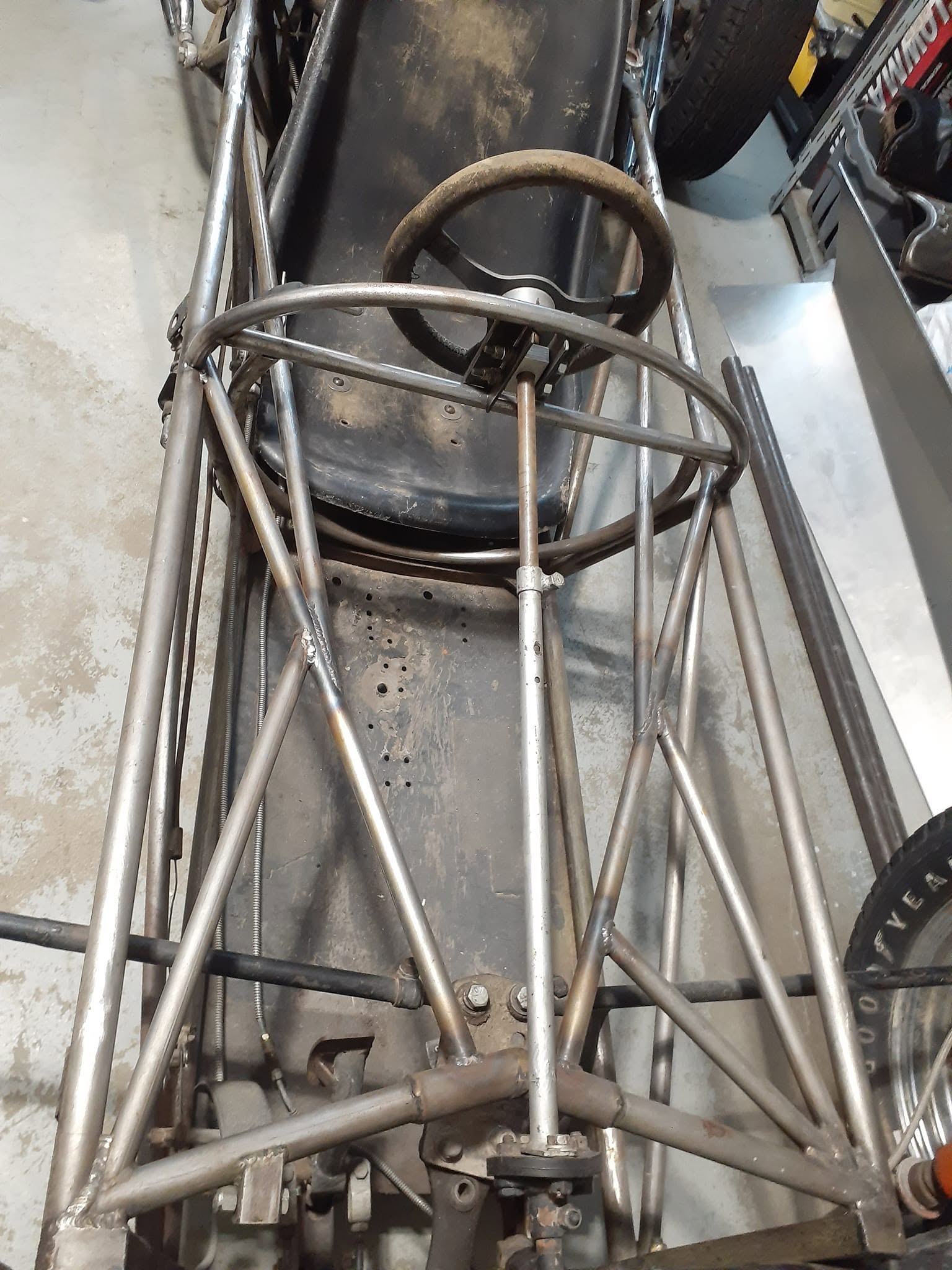
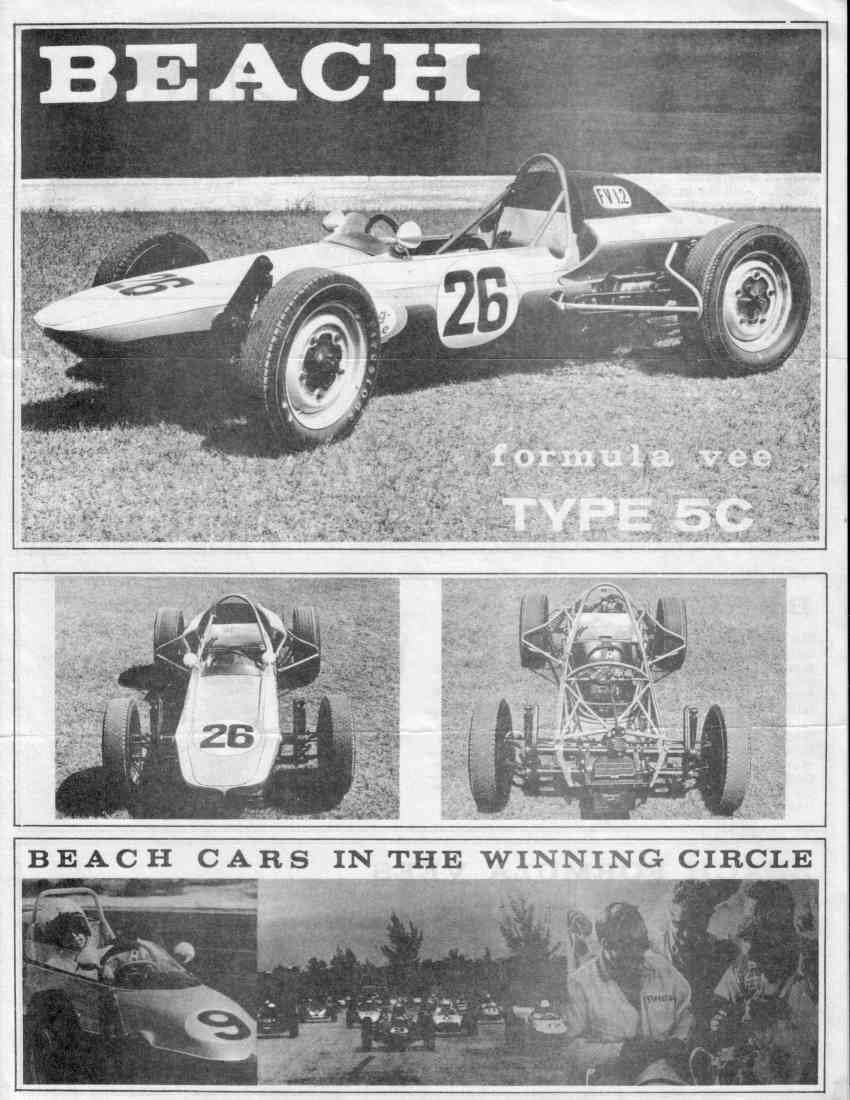
Here is an image from a FB post that I found and an original Beach advertisement that show the original chassis structure and the four tubes that were removed from mine. I’ve found multiple Beaches on FB that also have at least the two tubes on either side of the driver removed, so that modification appears to be pretty common. Structurally, who knows what missing those tubes does, but it’s not like any of us have a chassis/suspension dyno to scientifically test.

Justin
As they say,” A picture is worth a thousand words”, so finding that may prove be helpful. Greg Jacobs at ignite performance in Arvada has restored a Beach sports racer in the past and may have some helpful info regarding the marquee. I’ll reach out to him as he is a friend and mentor.

Best
Tom

Dash Gussets
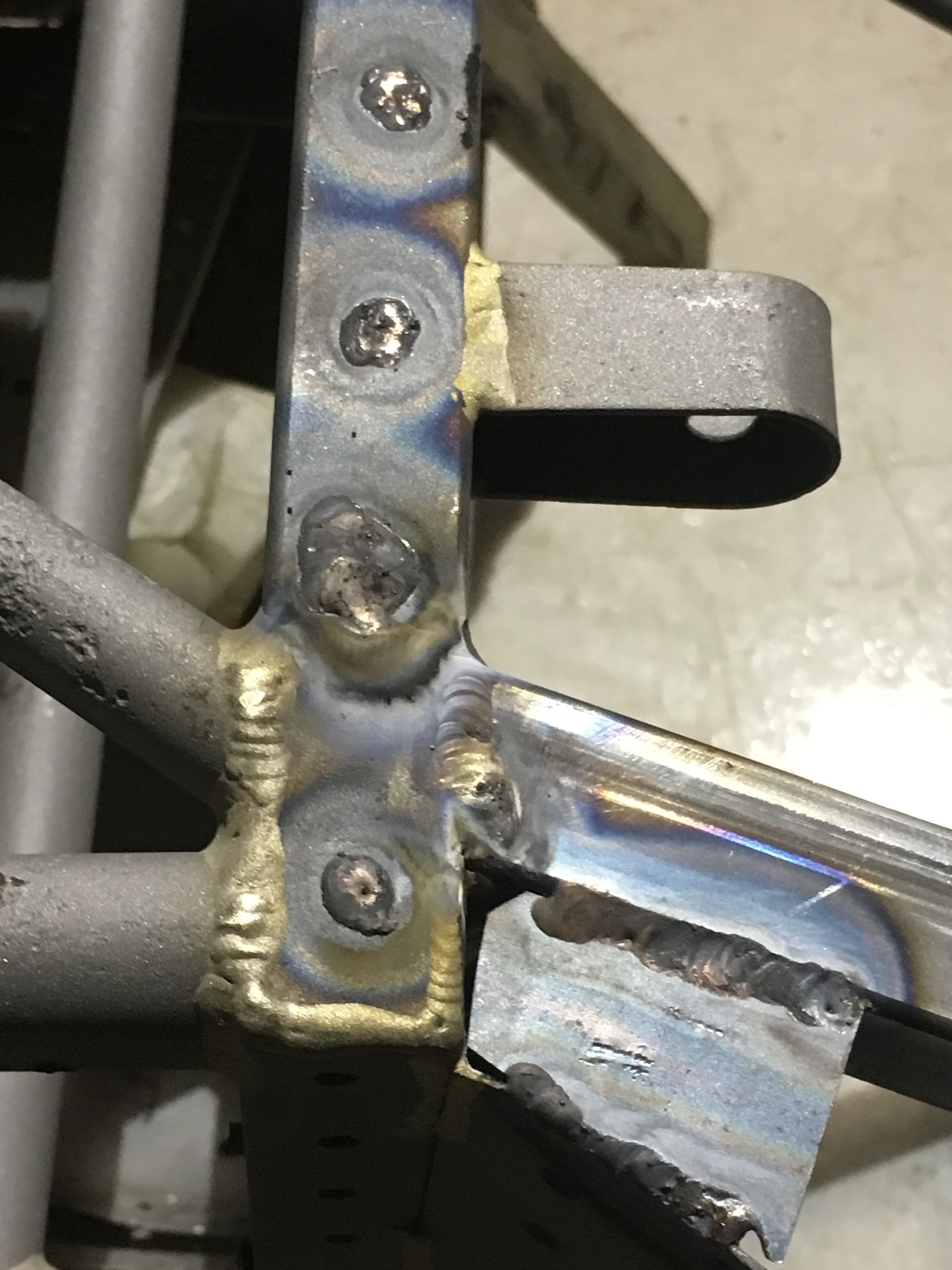
I welded up the crack in the dash crossmember and decided to fabricate some 18-gauge gussets to spread the flexing loading in this area to, hopefully, stop future cracks.

Finishing Welds at the the Abandoned Tubing Intersections
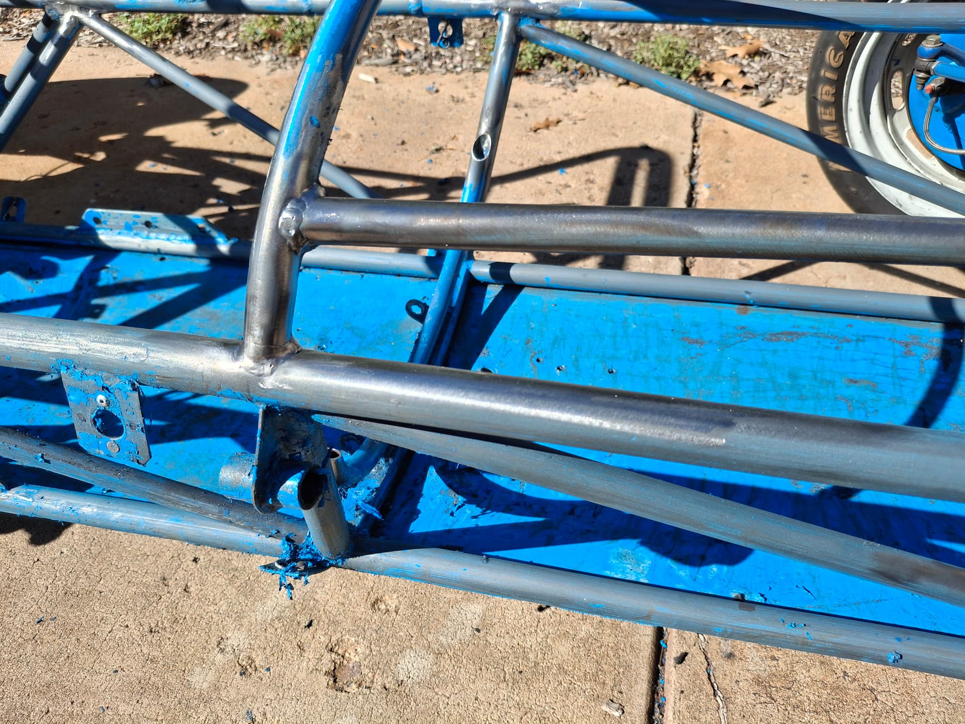
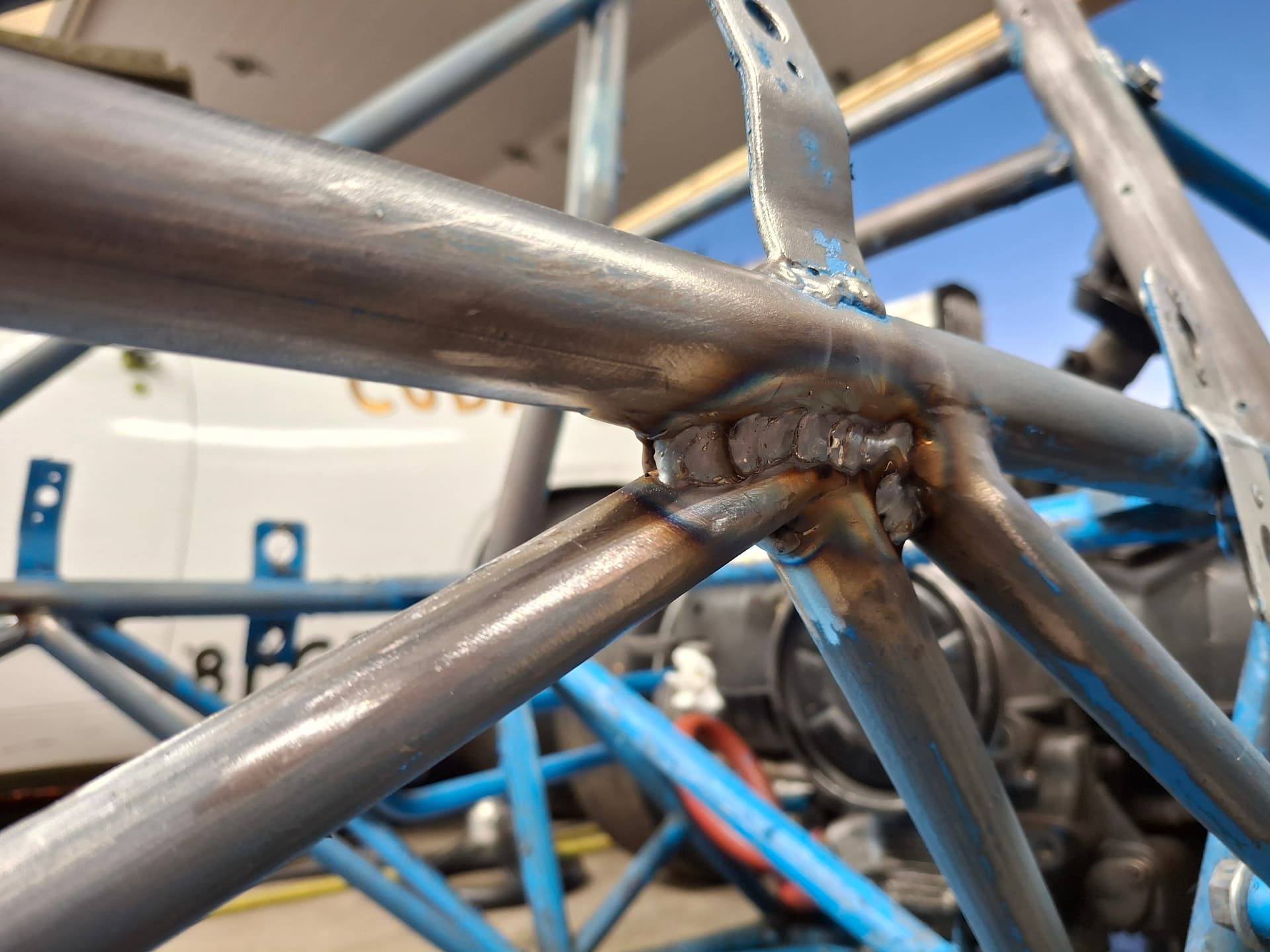
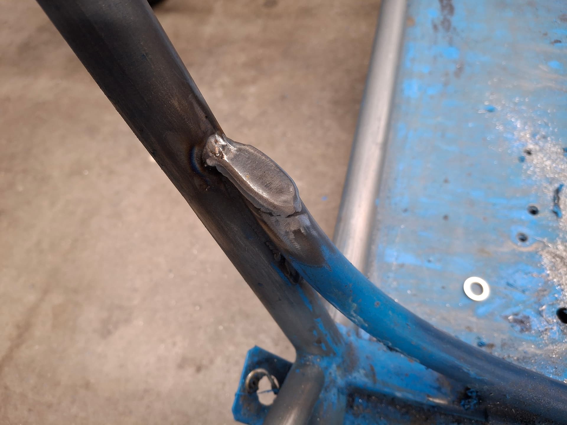
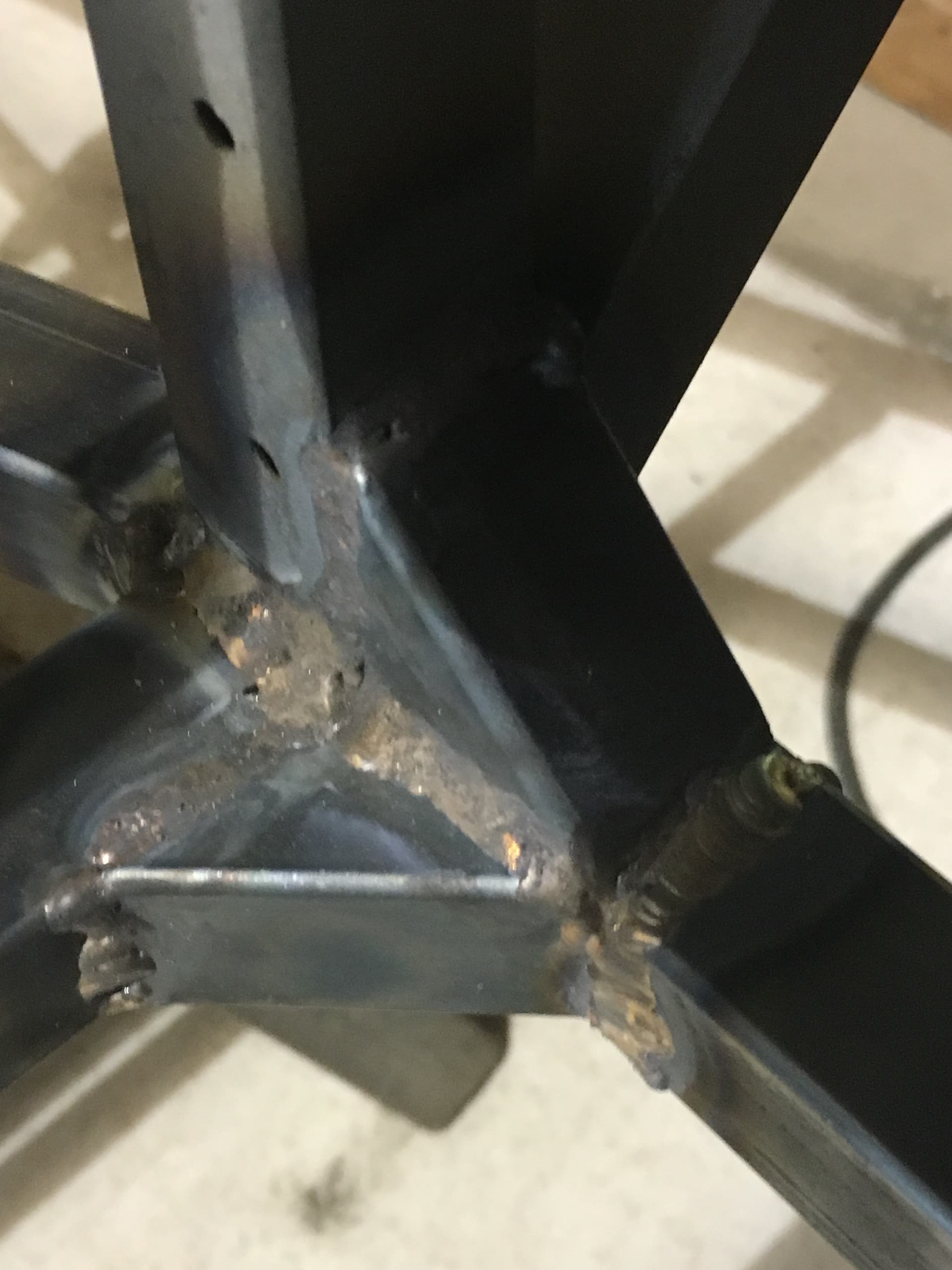
I welded up the different gaps left from the abandoned tubing at the dash cross member and midsection. I capped the cuts in the hoop at the dash area as well.

Throttle Pedal Return Spring Tab
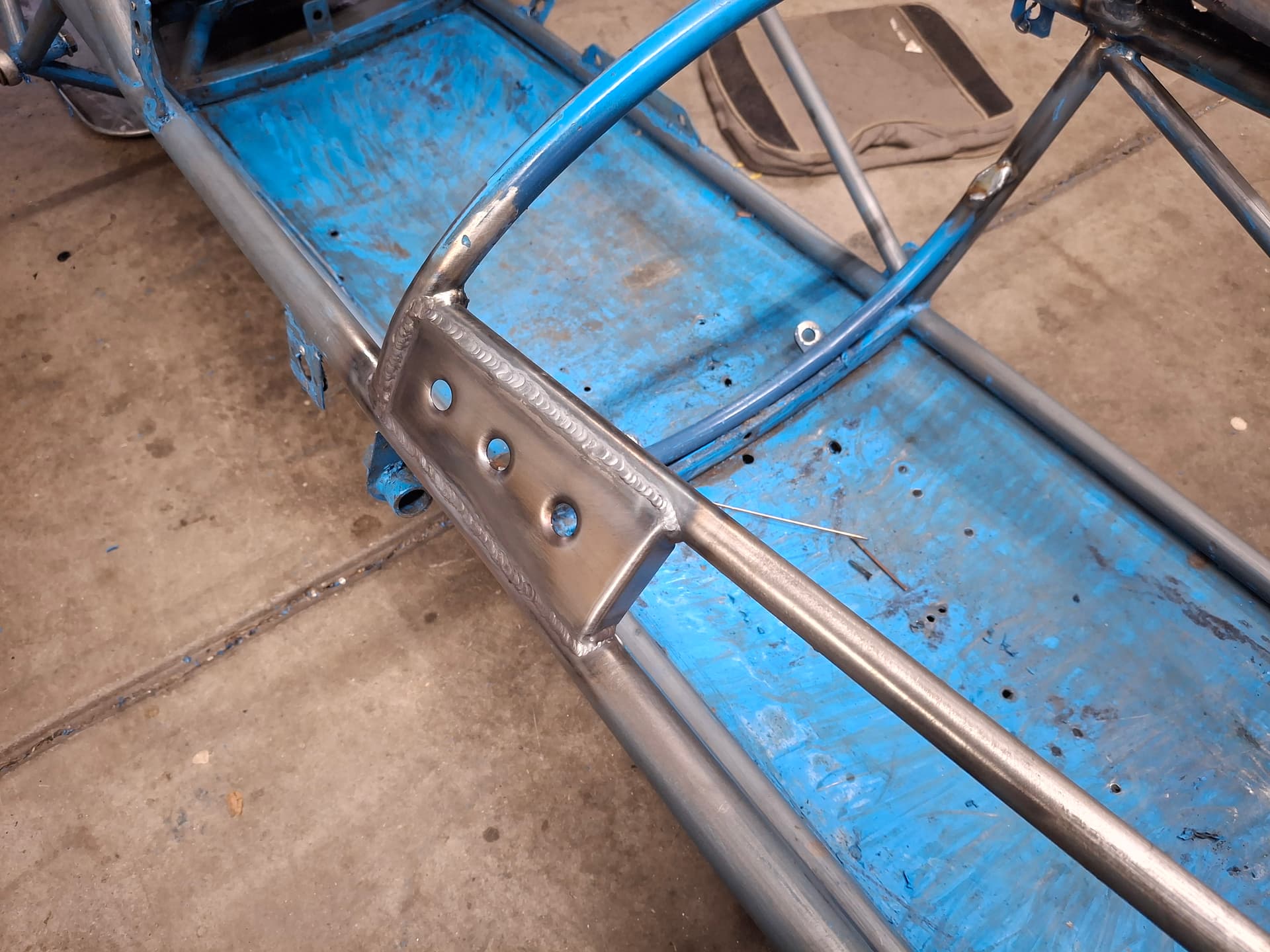
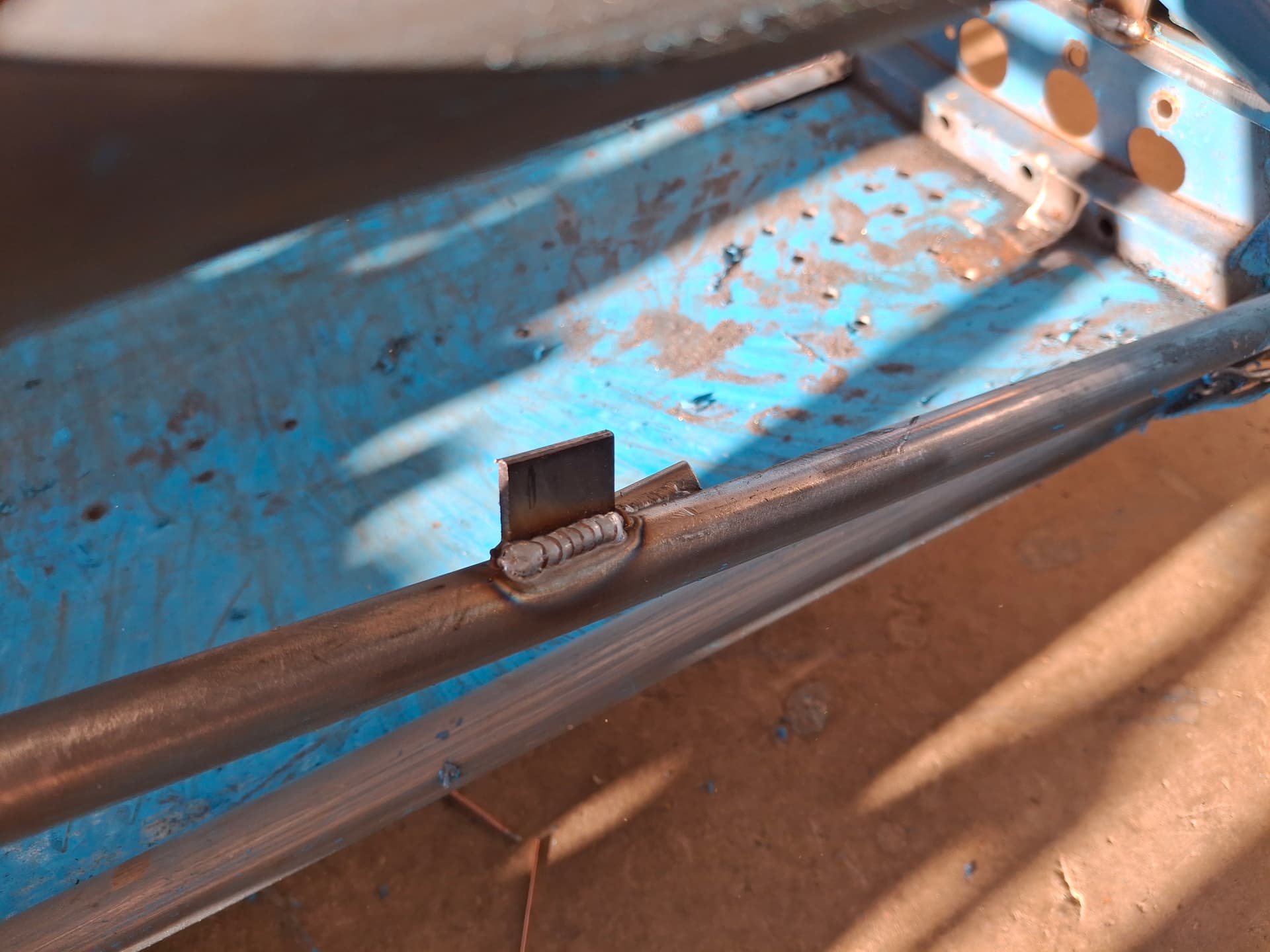
The throttle pedal return spring was a very long affair wrapped around the throttle cable mounting tube with safety wire. I welded on a tab that I’ll drill a hole in to where the spring has a place to hook securely to the chassis.

Tom @Sportsracer, yes, I have a large #14 ceramic cup with a deffuser that lets me get a good 5/8 stick-out for those tight spaces. I love it, but boy does it use argon. :grin: I’d love to try one of the clear glass cups since I get they really light up the welding area.

Post Alert:
@jonUU
@Sportsracer
@Datsun78
@Bob_Alder
@Rich
@Nick_H
@jackson_prime101
@Raybob9289
@GeorgeCurl
@dreimol

1 Like

I sure wish I had your skills! Mine are basically limited to driving and writing checks!

1 Like

Justin I really enjoy using dimple dies, they take thin sheet metal pieces and make them rigid and look good. Nice work on the repairs.

I have been using the clear cups for a few years and they do help but they can only do so much for these 71 year old eyes. I always use mine with the diffuser screens even if I don’t need the stick out. The shielding is so much better.
How much CFH of argon are you using? I’ve found that at elevation (even Denver’s 5280 ish) you need much less than sea level. If there’s a benefit to less oxygen this is it. I typically run in the area of 10-12 at 9700’ I would think in Denver you’d be in the 15-18 range. Remember when Jody spec’s a CFH he’s at much lower elevation. Extra argon won’t hurt anything in the weld but sure will empty your wallet faster.

Best
Tom

1 Like

Thanks, @Rich and Tom @Sportsracer.

Tom, I’ve really grown to like dimple dies for the reasons you state. If one’s never worked with them, it’s pretty amazing how much they stiffen thinner sheet. Regarding argon, I’m at 20 CFH with the #14 cup for mild steel. Interestingly and perplexingly, whatever alloy the Beach chassis is made of, it wants a lot of argon and a contaminant tolerant rod. With a #7 cup and starting with 10 CFH to weld those dash gussets, I struggled terribly to get a clean weld with the puddle popping. I cleaned everything over and over again and tried different rod allow with no help. I gradually cranked up the CFH to 25 CFH. Yes, that #7 cup was howling with argon, but that’s what the metal wanted along with ER70S-6 rod. I don’t get it, but I’ll stick with that rod and flow for this chassis. I wish I was more experienced in TIG since there might be another way?

Justin
As I’m not behind the helmet I’m just speculating here, I wonder if the contaminates are coming from the inside of the tube. As the puddle forms the internal rust is drawn into the weld puddle causing the popping. Yes more Argon helps but tig likes clean metal. My suggestion is to try tig brazing with silicone/bronze rod. Jody has few videos on this. This will get you within 85-90% of the strength of welding on mild steel. As you are on the surface of the metal the dirty metal issue is reduced. It’s not a hard process but practice first so the finished product on your chassis has integrity.
As I’m typing this I wonder if part of the problem could but that the chassis was originally brazed together using a gas flux process. Very common back in the day. Before I rebuilt my chassis I tried to fix a previous repair and welding it was next to impossible. The popping and poor penetration were very frustrating. Once I switched over to brazing the repair was much better.
Warren Coble at Another Source of Supply (303) 781-6767 has the rod, start with .030 rod if the fitment is good, larger if there are gaps.


A few pics of the finished brazing prior the clean up with a wire brush. No flux is used as the argon keeps the weld area clean.

Best
Tom

Hey Tom @Sportsracer, I think you might be onto something regarding the impurities from within causing the issues. The chassis tubing is thin wall, so it’s likely that as the base metal melts into the puddle, there’s rust/oil entering the weld from within. The chassis is heliarc welded, so no brazing from what I’ve found so far. I’ve done oxy-acetylene brazing but never with a TIG.

Dashboard Fabrication
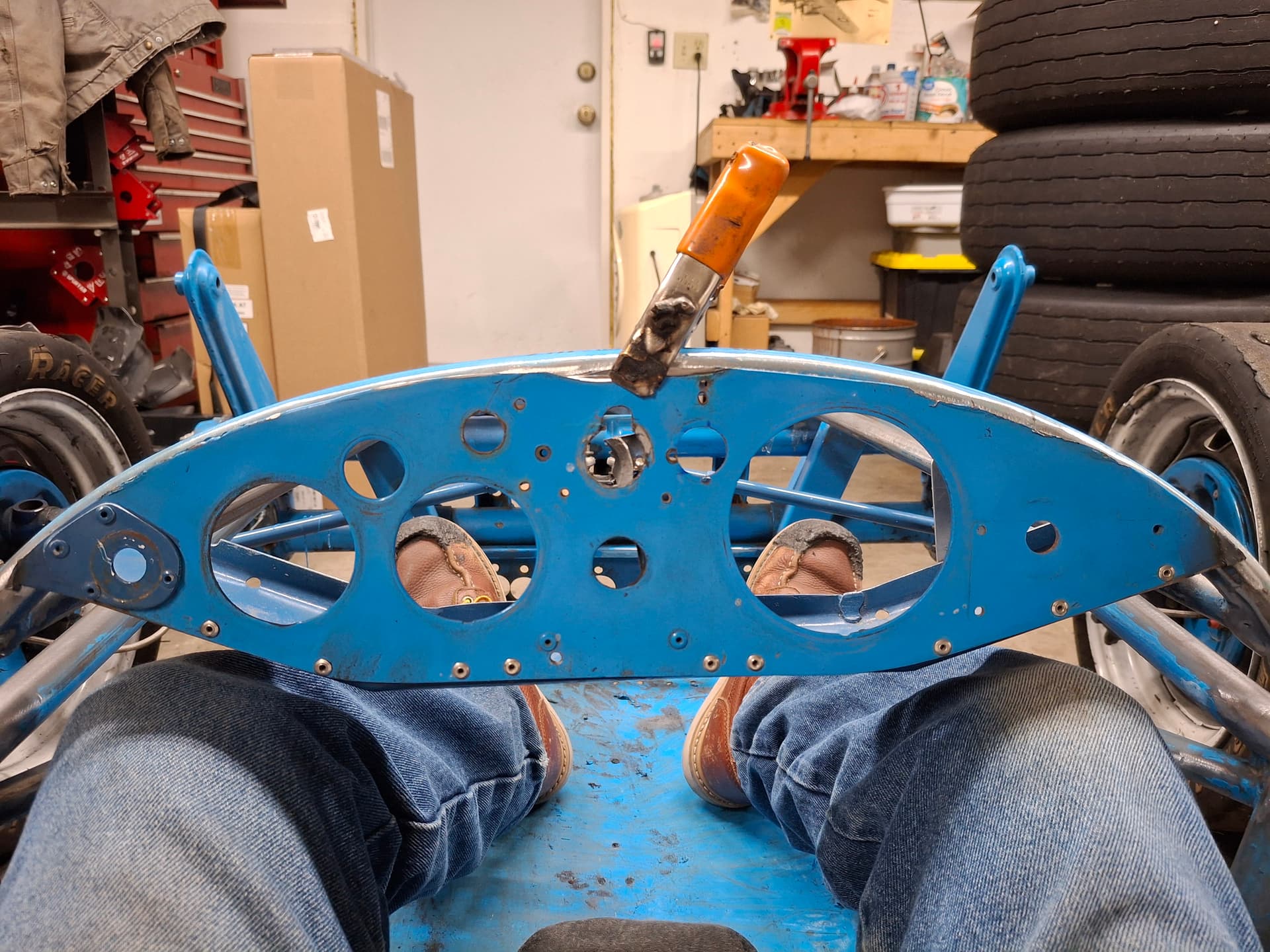
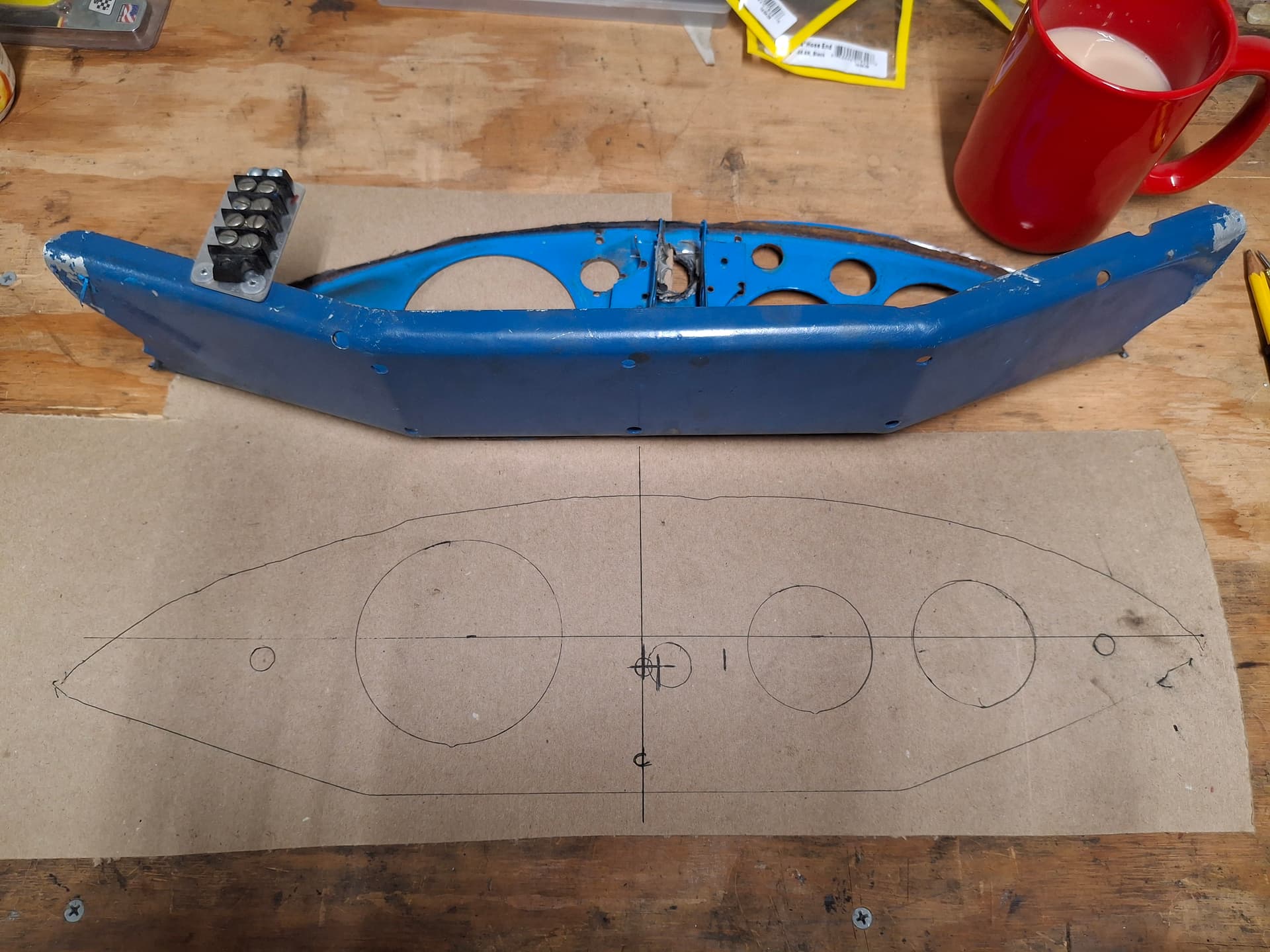
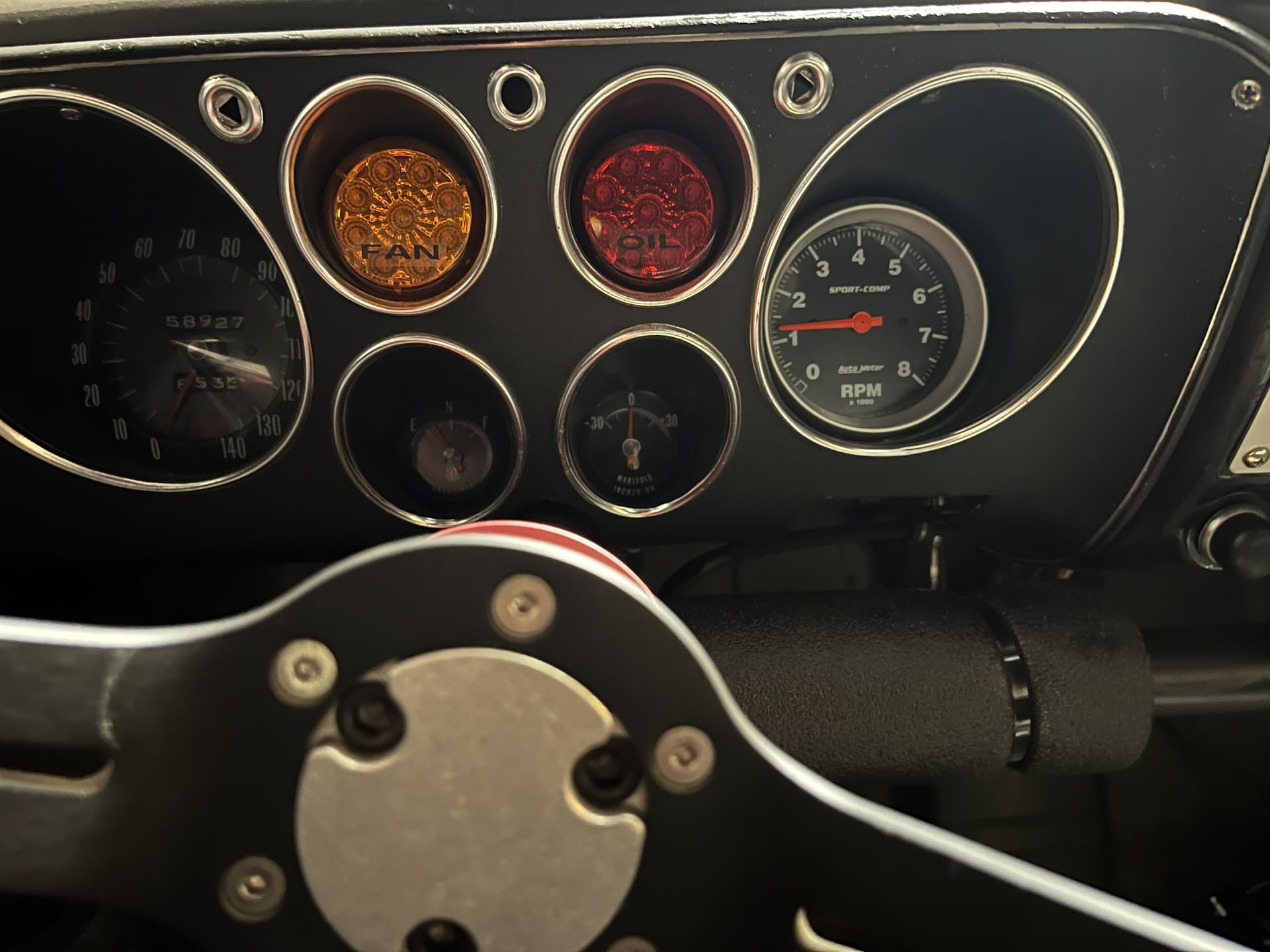
The old dashboard was all sorts of modified with switch and light holes all over the place, a resized hole with a pop-riveted cover, and no symmetry. Rather than trying to salvage it, I decided to rebuild. Interestingly, the car had an air pressure warning light on the dash with a sensor screwed onto the engine cooling fan shroud. While I’m not sure it worked or did so accurately, the thinking was if the fan belt was thrown and the fan stopped turning, the alarm light would illuminate. I’m deleting that sensor and alarm light because it isn’t necessary with an oil temperature gauge, and the sensor is an HVAC unit from what looks like the 90’s and wouldn’t have been on a 1967 car. If the fan belt throws and the lack of fan rotation heats up the engine, the oil temperature will tell the tale. I think an oil temperature alarm light is the better way to go, but I’m very good at checking my oil temp gauge and likely won’t add another switch and light.

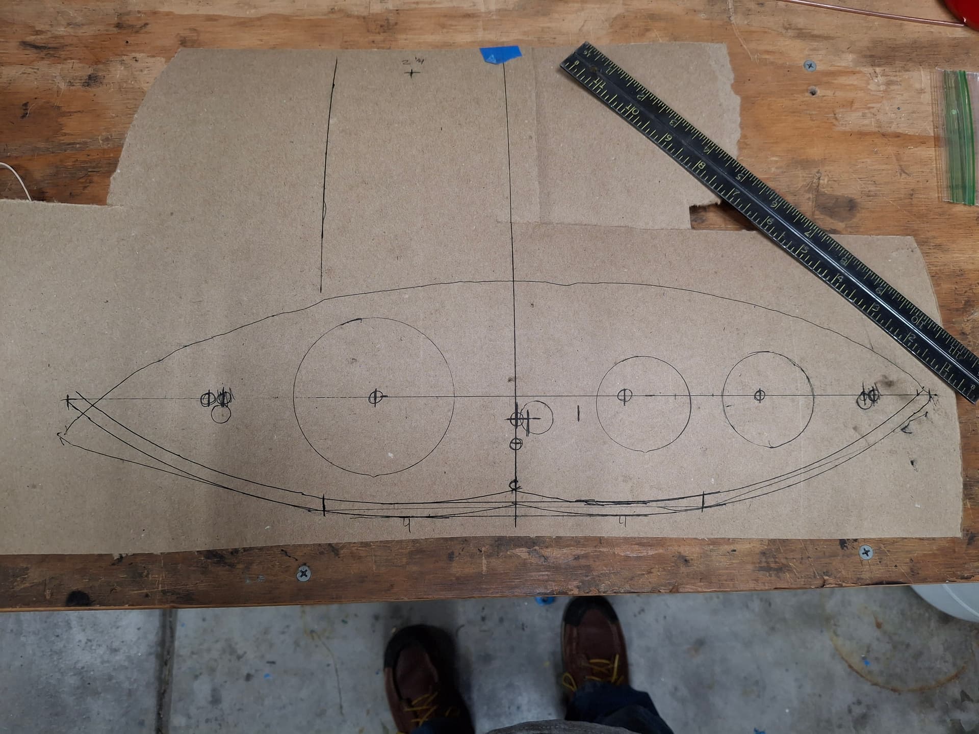
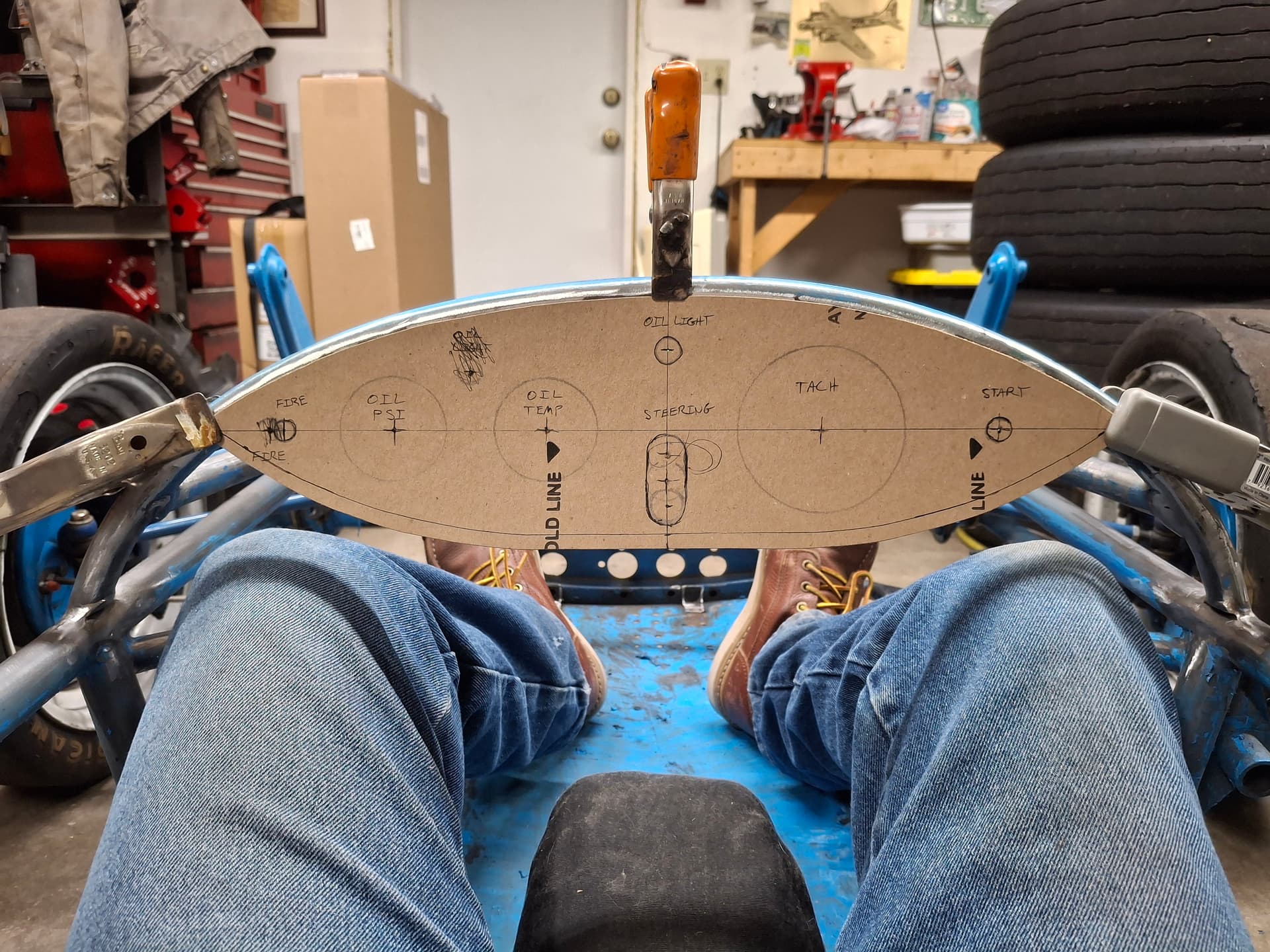
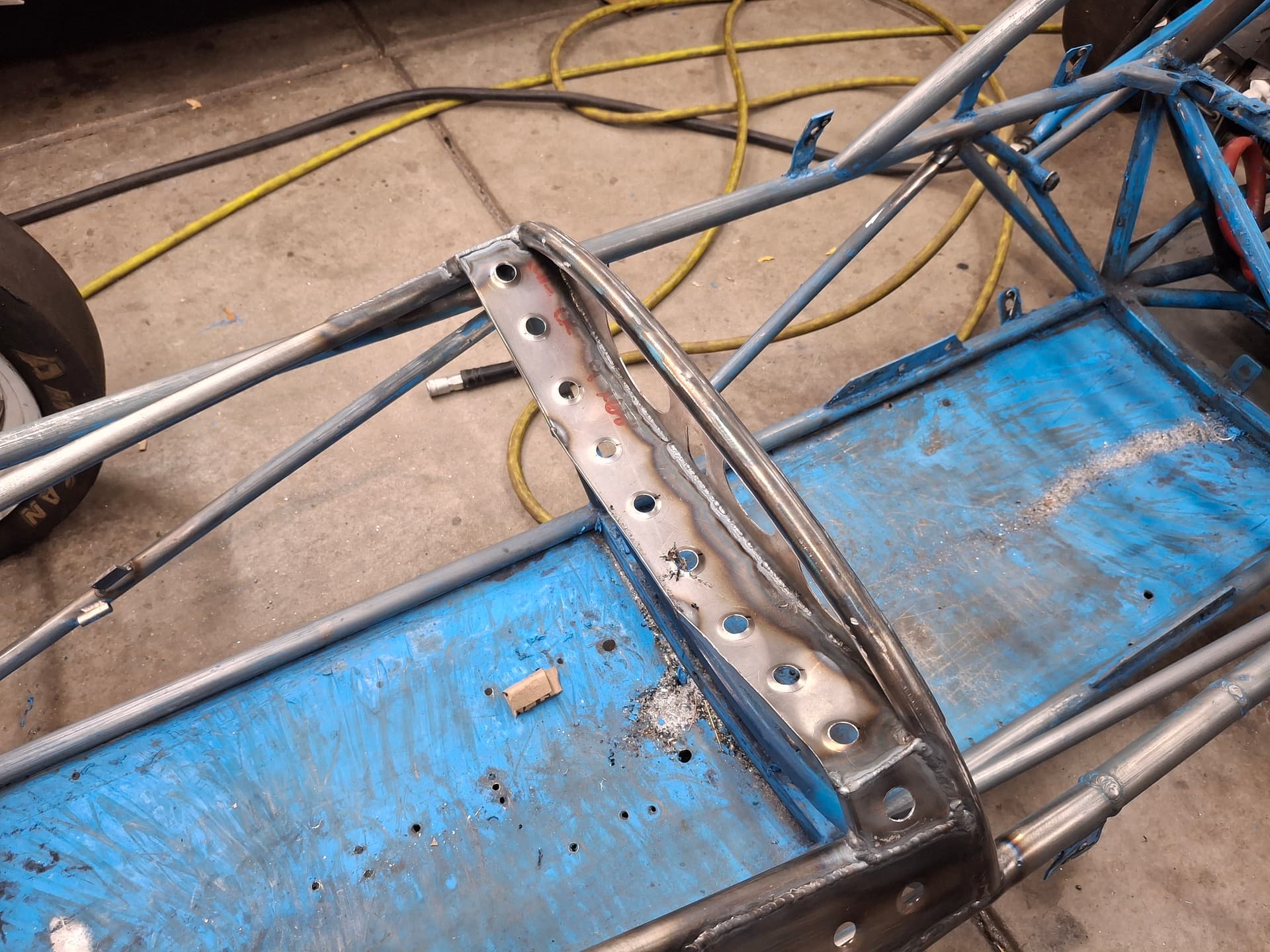
Originally, the dash had a bottom 3/4" tube crossmember like the top and the dash panel was stitch welded to both, but the bottom crossmember was cut out at some point for knee room. The lower portion of the dash was reshaped and an aluminum gauge shield added with pop-rivets. For some reason, nothing on the dash’s layout aligned (see the photo of the tracing I did). The tach center was higher than the oil temp gauge, and the oil pressure gauge was then higher than the center of the oil temp gauge but not centered with the tach. The ignition switch and fire pull handle were also off center. The bottom modification to the dash was asymmetrical. None of this layout was because of space restrictions, so it’s almost like people just pointed and drilled/cut over the years. It got the job done and served the car well, but it would drive me nuts looking at that in the garage or while on grid.

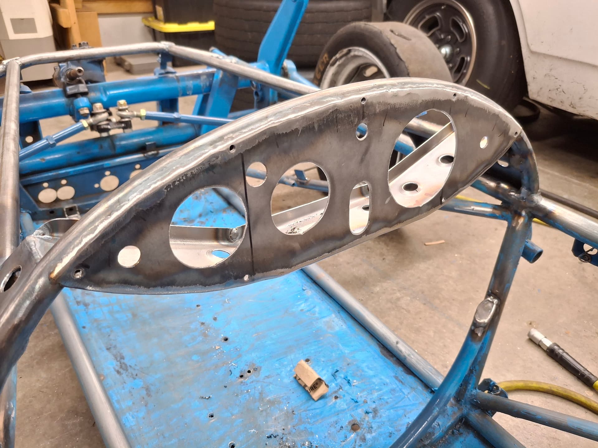
I cut out and traced the existing dash to get the general shape, and then I played with a couple new template to clean up the overall shape of the dash and to layout the gauges, switches, and light. The dash gets a tach, oil pressure gauge, oil temp gauge, oil pressure warning light, ignition toggle switch, starter push button, fire suppression pull handle, and a hole for the steering shaft. The original steering shaft was fixed, but while I’m at it, I’m going to build three different height adjustments into the steering shaft with a slot in the dash rather than a single hole.

I fabricated the dash from 16-gauge steel and the lower panel from 18-gauge steel that doubles as the structural support that used to come from the missing 3/4" tube and to protect the gauges from the driver’s knees–and vice versa. I welded up the many holes drilled into the upper crossmember over the years. I welded the lower panel to the dash and continuous welded the dash panel to the upper crossmember. The dash will receive a cover, which is what the drilled and tapped holes in the dash are for. I’m going to keep people in suspense about the cover for now, but I’m quite excited.

Post Alert:
@jonUU
@Sportsracer
@Datsun78
@Bob_Alder
@Rich
@Nick_H
@jackson_prime101
@Raybob9289
@GeorgeCurl
@dreimol

Justin
If in fact contaminants are entering the weld, the joint is compromised. One of the advantages of tig brazing is it’s on the surface so internal tube contamination isn’t an issue. The other advantage is much less shrinkage and distortion as less heat is used.

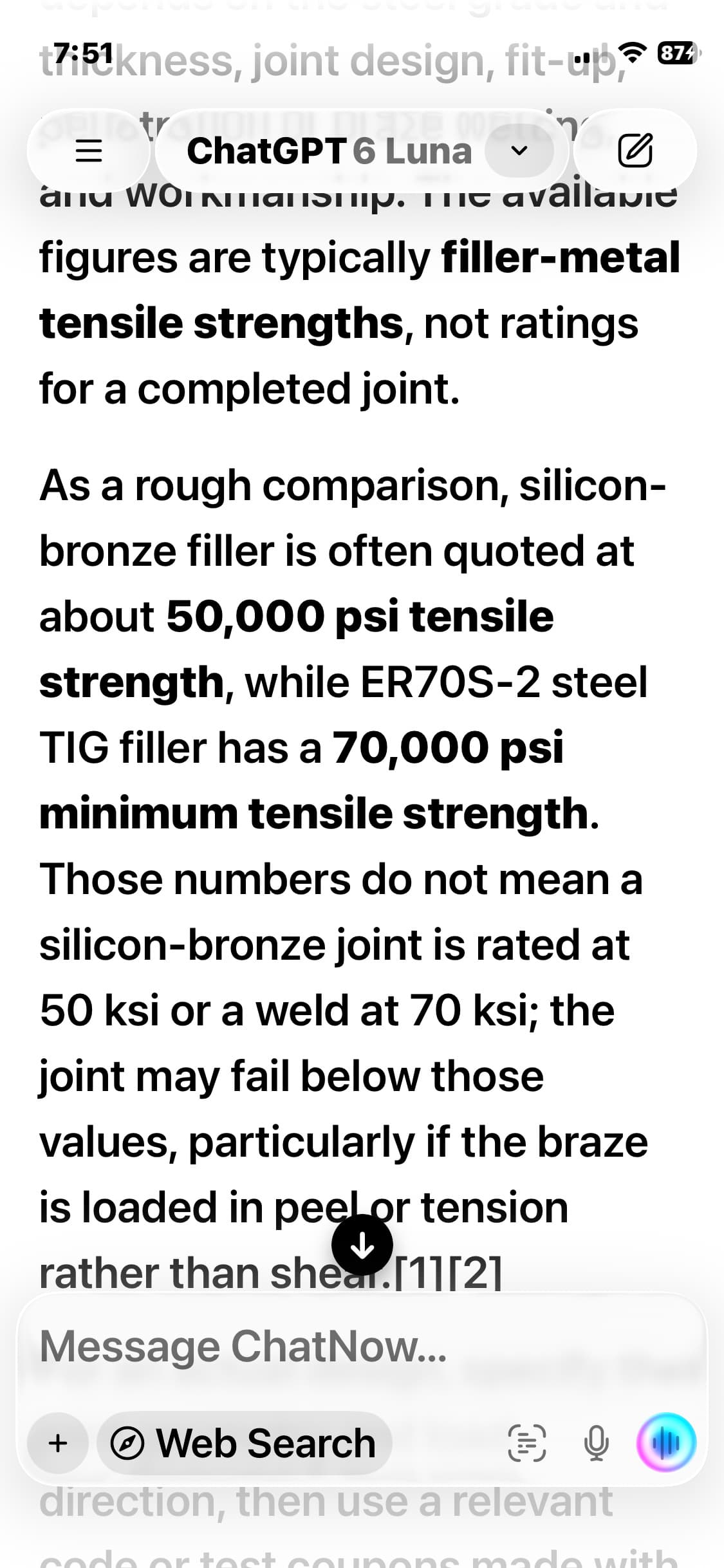
This is from AI, a discussion regarding the relative filler metal strength. However a contaminated weld will have porosity and be lacking proper fusion within the weld. No matter how strong the filler is, the strength of the joint will be well below the rating of the filler.

I would encourage you to try tig brazing as dissimilar metals will bond, also the fact that it is on the surface, internal contaminates will not be brought into the joint. A wider braze joint with its associated additional filler will produce a strong joint, likely superior to a contaminated welded joint.

As a testament to brazing, most of the formula fords on the grid have gas fluxed brazed construction. The Brit’s used it exclusively because in the 1950’s thru the early 1960’s (later on some marques) the technology of heliarc welding wasn’t in the picture in post war England. Gas welding produced so much distortion that the flux less brazing method was favored. In mild steel the strength was more than sufficient.

Now if I were to be fabricating new components I’d be using 4130 and tig welding it all together. Not necessarily true to the period correct credo some subscribe to but in the interest of safety I’d stand behind my decision to use modern materials and methods. This is exactly what I did in constructing new A arms and radius rods on my cars.

Again far be it from me to be telling you what to use and how to repair your car. Just trying to offer up suggestions and share my experiences in the crazy world of vintage racing.

Best
Tom

1 Like

My vote for the dash covering;
Engine turned aluminum sheet!

Tom

Justin, keep the air pressure switch and connect it to a BIG warning light positioned in your direct line of sight. When the fan belt breaks the cylinder head temps will spike long before oil temps become a concern. Ask me how I know.

1 Like

@Sportsracer, well, way to destroy the suspense! Yes, it’s getting an engine turned aluminum that I’m going to create myself. I guess a purist would call it “jeweling” since I’m not using an turning engine, but a rose by any other name would smell as sweet.

Thanks, Jon @jonUU. I didn’t consider the cylinder head temp spike before the oil has a chance to absorb the heat. I’ll run the switch and light past Jess Valentine to see if the VWs suffer a similar issue with spiking head temps. My inclination is that they don’t since the 1200 cc cars (probably 80% of RMVR’s FVs) ditch the generator, fan, and fan shroud altogether in search of the extra power and rely on passive cooling. My 1385 cc engine requires that I run the fan and shroud as a handicap against the smaller displacement, so the fan and shroud would go away if I had a 1200 cc.

Sorry dude, just my vote! I guess you never came by to see the Miata (the big bore version) where I did exactly the same. I used a product called Craytex, it’s a rubberized abrasive that worked very well. 2 hours in the mill to do the dash, but the result was worth the effort. Also did the center section of the console, where the auxiliary gauges live.

When I raced 100cc karts we had a head tempature gauge that used a sensor which was under the spark plug. The sensor was used in place of the gasket between the plug and the head. It was a thermocouple style setup so no outside voltage source was needed, the lead wire, much like a capillary tube could not be adjusted in length. So you would have to find a sensor with an appropriate length lead.

Again sorry for breaking the bubble!:grinning_face:

Best
Tom

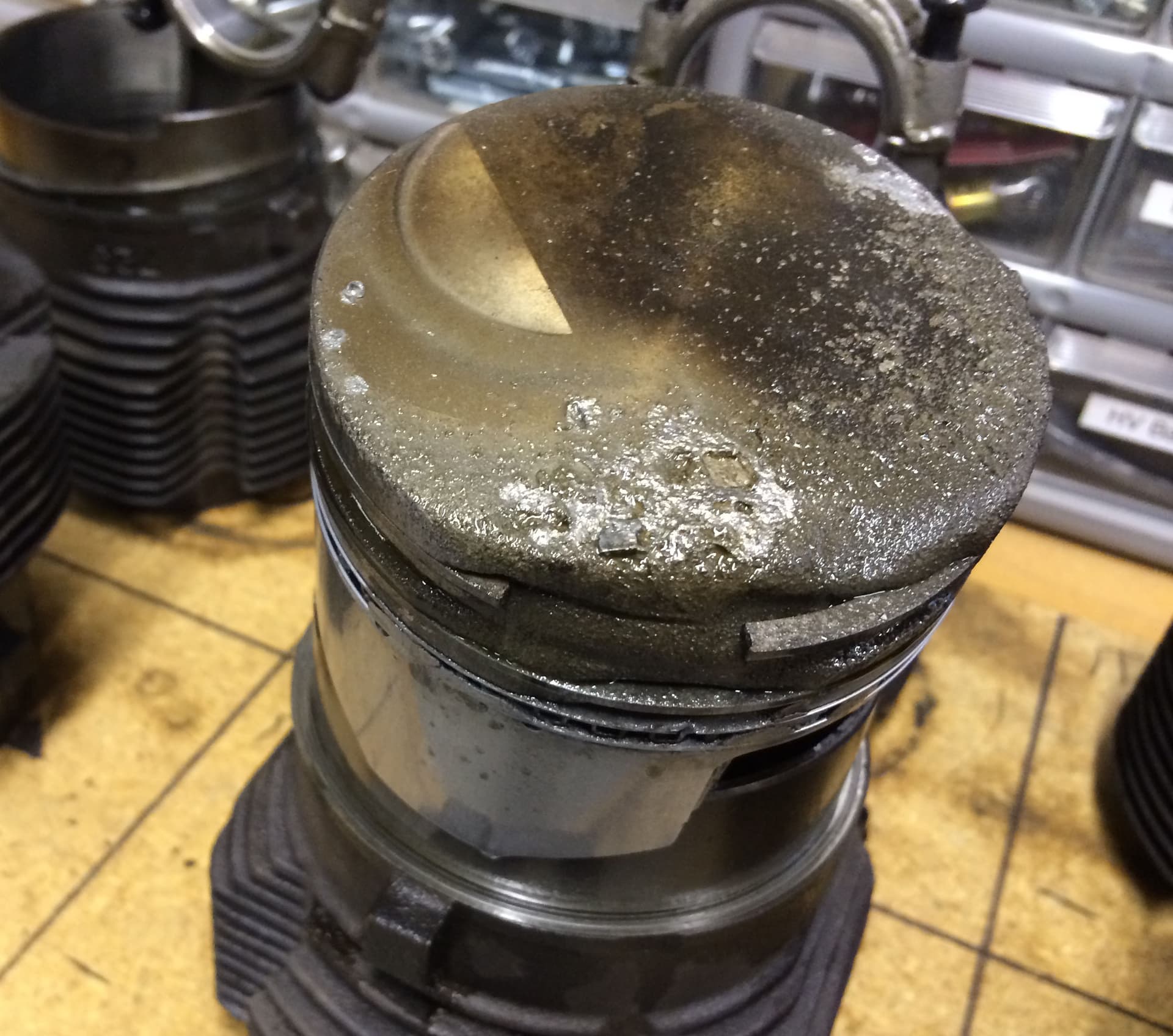
Yes, always best to talk to those with the experience. I’m surprised 1200 cc FVs run without a fan. At my start with RMVR, I lost a fan belt at PPIR and failed to see the small factory generator idiot light illuminated. In less than a lap, things quickly went south, breaking rings and melting a piston. I now have the air pressure switch and big bright warning lights for fan and oil pressure.
As possible sources for CHT thermocouples utilizing a spark plug, if nothing’s available specifically for your engine, look at Pegasus or an aircraft supplier like Aircraft Spruce.


You want the pressure switch and warning light for a fan car. With monoposto cars, you can just have a warning light from the charging system to know that you tossed a fan belt. With a gutted generator, you don’t have that option. When you toss a fan belt, you’ll gain about 4hp. If you’re paying attention, you’ll notice. If you’re waiting for the oil temp to spike, you’ve waited way too long.

The 1200 cars with “passive” cooling cool much better than the fan cars, not worse. The air flow at speed from a well-ducted setup is way better than the silly fan. We ditch the fan for the power, but the airflow is insanely good. You just can’t run them while sitting still. I idle the Zink on the grid to get the oil temps up, the Mysterian doesn’t get started until the 1 count. On the newer cars, you’ve only got a couple of minutes sitting still before you cook the cylinder heads without a fan, and you’ll do that long before you even get the oil temp gauge to register.

Also, I’d check the 1972 GCR carefully, but I’m skeptical that welding that brake line support to the front beam is legal:)

§5.1: no front suspension component “may be altered, modified, or changed… unless specifically authorized.”
§5.3a: front suspension “shall be standard VW sedan,” followed by the complete list of allowed modifications:
Removing one torsion bar
Any anti-sway bar mounting hardware and trailing-arm locating spacers
Shocks that mount directly on the standard mounts
Centering the steering box, with new tie rods
Altering or replacing the steering column and wheel
Any Pitman arm, and altered steering arms (spindle untouched)
Modifying the torsion bars
Altering or removing the rubber part of the bump stop
Free caster and toe

It was legal, I think, in 1973 to start welding on brackets, but it’s illegal in your class. Be careful:)

Thanks for the input, @jonUU and @berck.

@berck, In the spirit of some friendly academic debate, I disagree that welding brake line mounting tabs to the front axle is illegal, and your recommended air-pressure indicator light system supports my interpretation.

My reasoning is that Section 5.10(d) states that brake and fuel lines are unrestricted “provided that no unauthorized modification of any other components results.” Also, Section 5.10(a) states that “fasteners (nuts, bolts, screws, etc.)” are unrestricted, and a c-clip mounting tab is a type of brake-line/hose fastener. The very allowance of any brake line and fastener comes with authorizing the modifications necessary to install that component per the manufacture instructions or industry standard so long as the modifications have no additional purpose, which would be an unauthorized modification. In my case, the manufacture instructions and industry standard for adapting a hard brake line to an AN brake hose and that hose running through moving suspension components require a secure, mechanical fastener at the joint to limit work hardening of the lines and to stop the hose/line from rubbing on other components. A welded tab with a c-clip adapter is one faster option included in the instructions and industry standard and is legal per SCCA and RMVR. In this case, both the brake hose and line are legal along with the means to fasten them, so the tabs are covered under two of the approved modification in Section 5.10.

Now for the air-pressure warning light as an analogy: The 1972 GCR in both the universal allowed modifications for all cars and the FV section doesn’t authorize the addition of an air-pressure indicator system. One interpretation could be that the sensor falls under the FV section 5.10(b) modification that “wiring” is unrestricted, although “wiring” suggests the actual wire rather than “electrical system” would suggest components like a switch and lamp. The other interpretation, which I use, is that SCCA’s standing practice is that the “replacement, addition, or removal of accessories, gauges, switches, and indicators” is legal. That rule is clearly defined for 1972 Production cars but not for FV, but it has been interpreted for decades now to apply to formula cars as well. However, installing the air-pressure switch you recommend requires drilling a hole in the factory fan shroud for the switch’s pickup orifice and drilling holes in the fan shroud to mount the switch body since the factory shroud never had such a switch. Under your interpretation, the shroud cannot be modified to install the switch, just as the axle cannot be modified to fasten the brake hose and line. My interpretation is that–whether we use the 5.10(b) “wiring” to allow the switch or if we use SCCA’s standing rule for adding/removing switches/indicators–these modifications to the fan shroud that do not impact performance are allowed because they are required in order to use the unrestricted indicator switch, just as welding a mounting tab to the front axle for the sole purpose of mounting unrestricted brake lines is allowed.

Now, from a practical standpoint, any scrutineer who would rather see a 20" long floating brake hose running from a tab on the chassis through moving suspension components to the wheel cylinder versus a hard line and 16" long brake hose securely, mechanically fastened and routed isn’t someone I’d trust with my safety as a driver. :grin:

Fortunately for you, we don’t have a scrutineer, but I’ve been told any amount of welding to the front beam is generally considered illegal in FV because it’s a modification to the front suspension that’s not explicitly listed. Why was it explicitly allowed later if it was already legal? Talk to Reah, he’ll have the answers. Mostly I wanted you to be aware this is a thing, I certainly don’t care. I also think you could have just put that tab on the chassis instead of the beam.

No need to modify the fan shroud at all for the pressure switch, mine is in the existing hole for the stock throttle cable that we don’t use in FV. Drilling an extra hole in it would be a lot more questionable to me.