Project Beachin': Restoring and Racing a 1967 Beach Mk5C Formula Vee

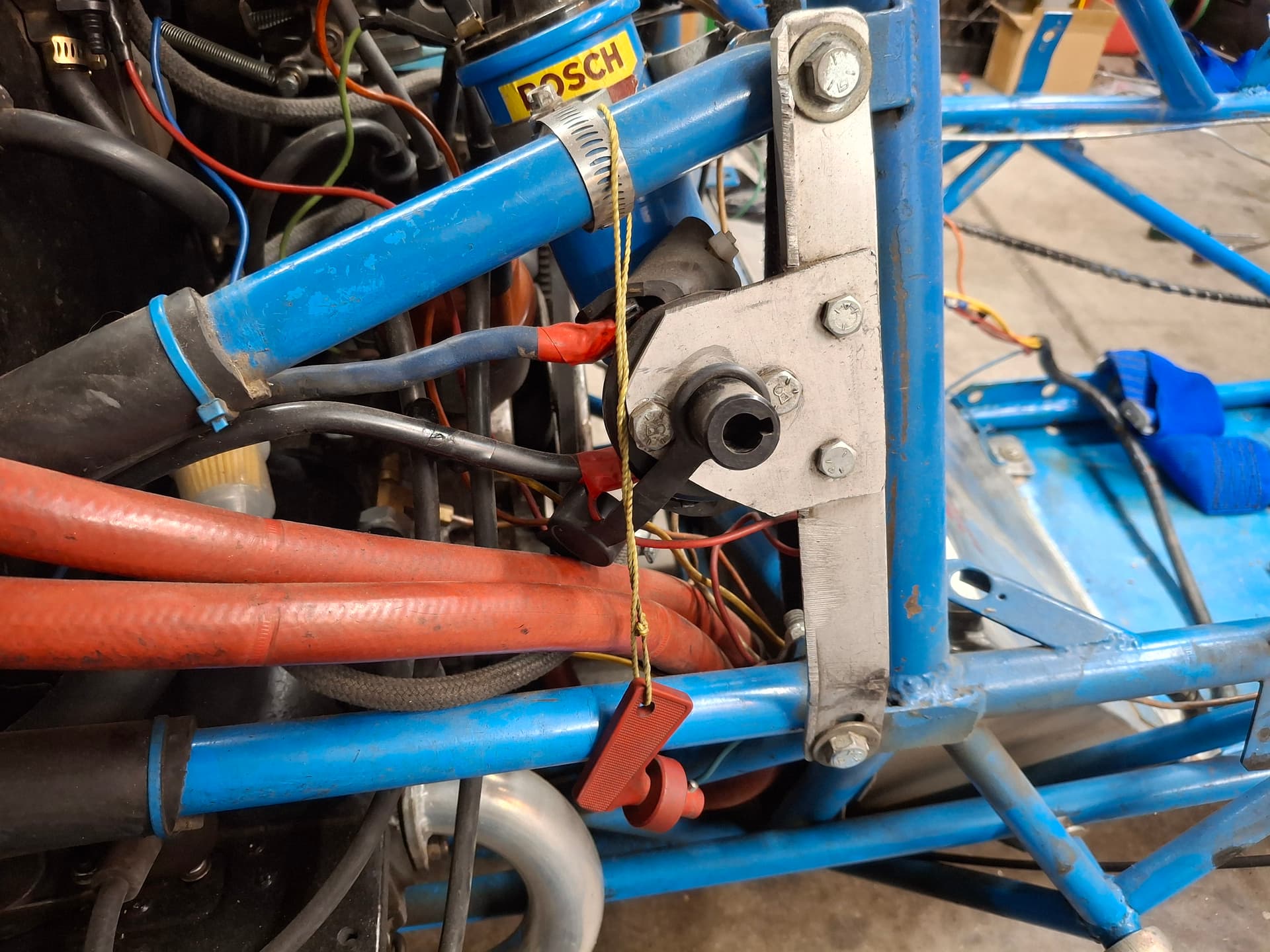
@berck, my understanding of the different GCRs and discussing the subject with others is that brackets to mount unrestricted parts or to use unrestricted fasteners are themselves unrestricted if the sole purpose is installing the part and if the bracket does not modify the performance of the factory part. The subject has been protested and won from what I’ve been told before I installed the brackets. The way I’ve installed the brake hose/line fastening tabs has no aero, structural, or other performance impact, so they fall under the rule for running the unrestricted brake lines and fasteners to secure parts. People have been drilling holes in the VW axle flanges since the 1960s to secure the brake lines, which modifies the axle by removing material, and welding on a bracket to accept a c-clip fastener for an AN adapter is the reverse method allowed by the rules.

Similarly, in the case of any FV running a pressure indicator switch that I used as an example, the pressure indicator switch and its means of installation are not specifically called out in any section of the 1967, 1972, or 1979 GCR–just like the modification to the front axle for brake line mounts isn’t called out. However, gauges, sensors, and indicators are unrestricted, and it is historically accepted practice to allow the modifications to install them so long as the modifications do not alter the performance of the part. You could literally drill new mounting holes, drill a hose hole in a new location, and even weld a bracket onto the outside of the shroud to mount the sensor or three of the things because the indicator is unrestricted and those modifications won’t help or harm cooling.

Oil Breather Catch Tank
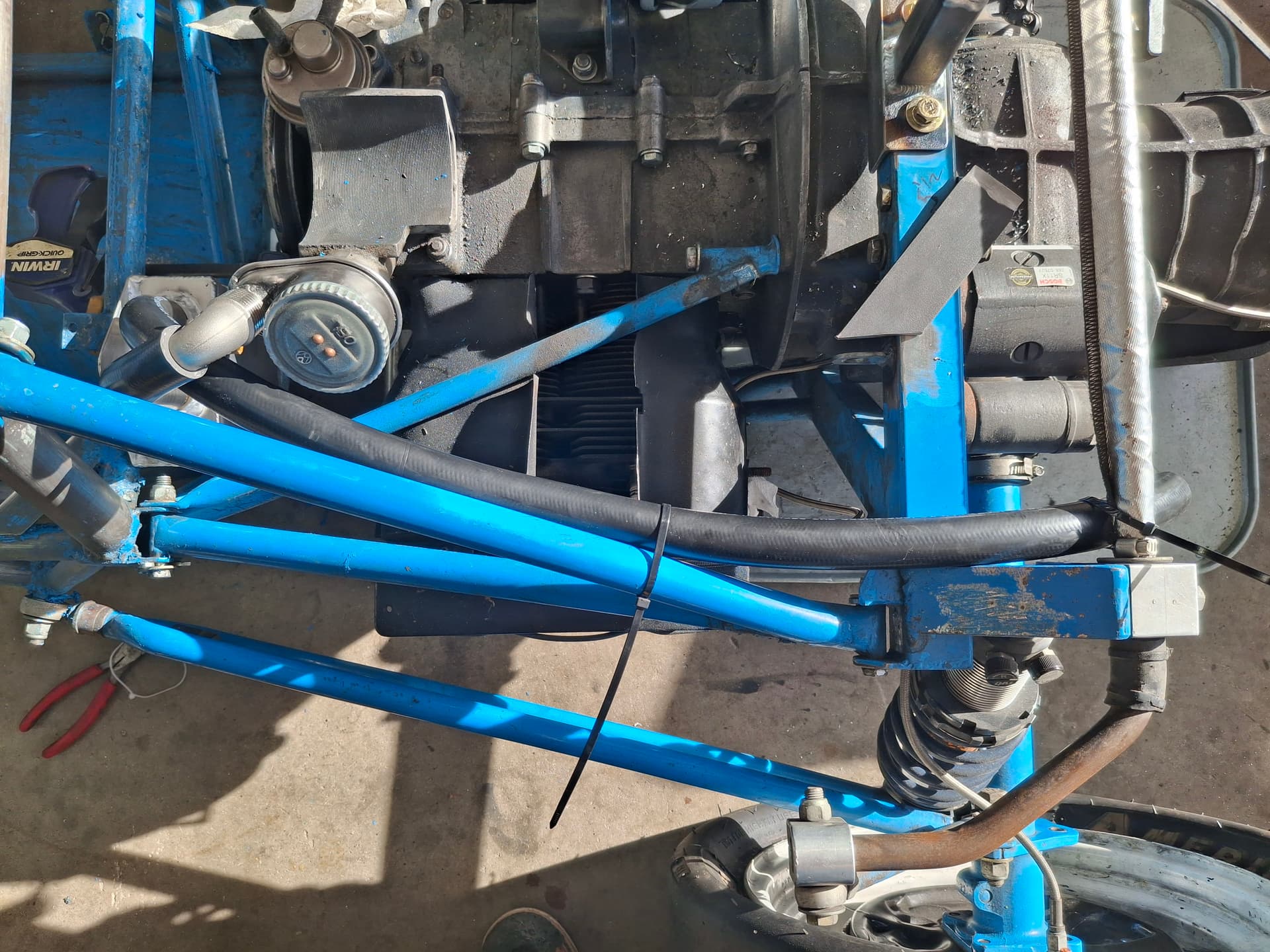
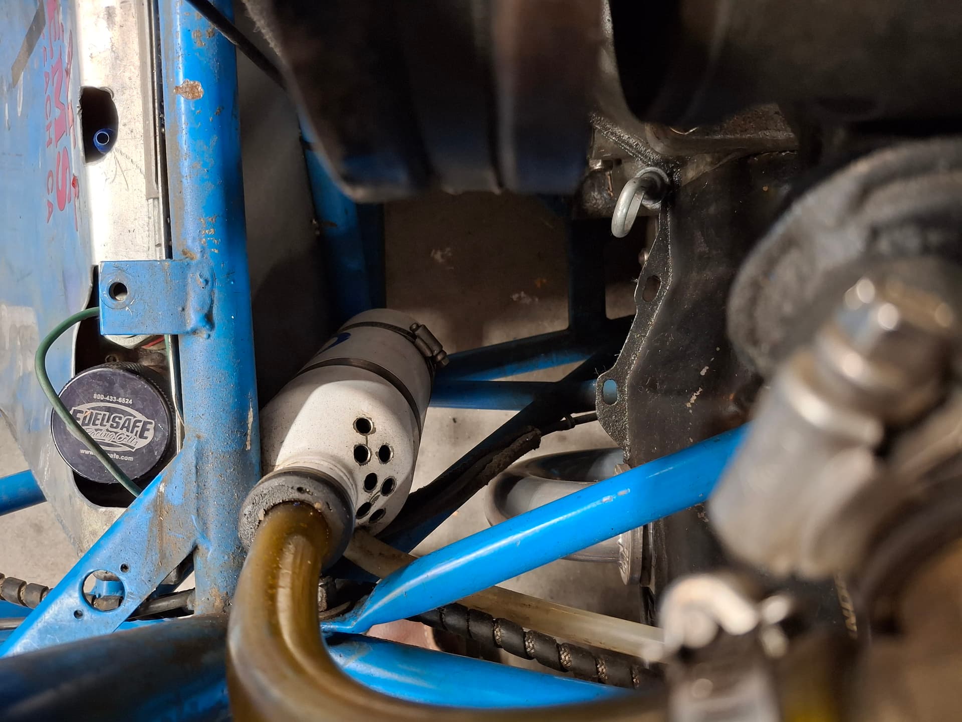
Formula Vee oil breather catch tanks intrigue me. They are probably the most personalized thing I’ve seen on Vees, each driver adding his/her own way of doing business. The vast majority are some repurposed container ranging from a rectangular metal quart from an old solvent can, a water bottle, a thermoses, an oil jug, etc. They are strapped to the chassis with zip ties, safety wire, hose clamps, shoe strings, etc. The hose from the engine breather and transaxle stuff into either the container’s original hole or a new one, and the tops are often riddled with holes for venting to atmosphere. No judgement intended–just pointing out the uniqueness of this little part. Here is the one on the Beach as I inherited it: a modified aluminum water bottle with 5/8" yellowed vinyl hose.

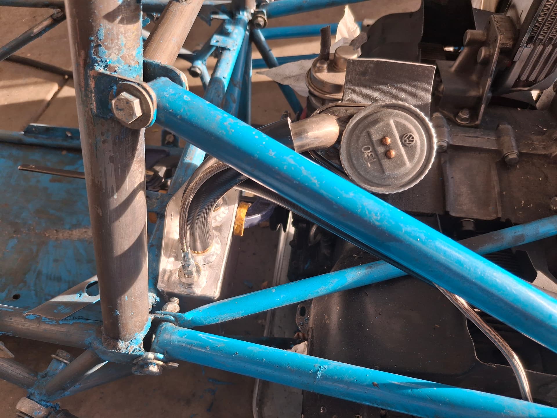
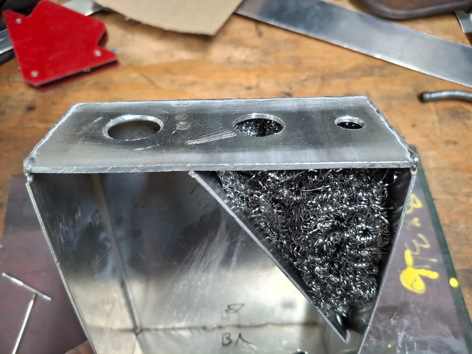
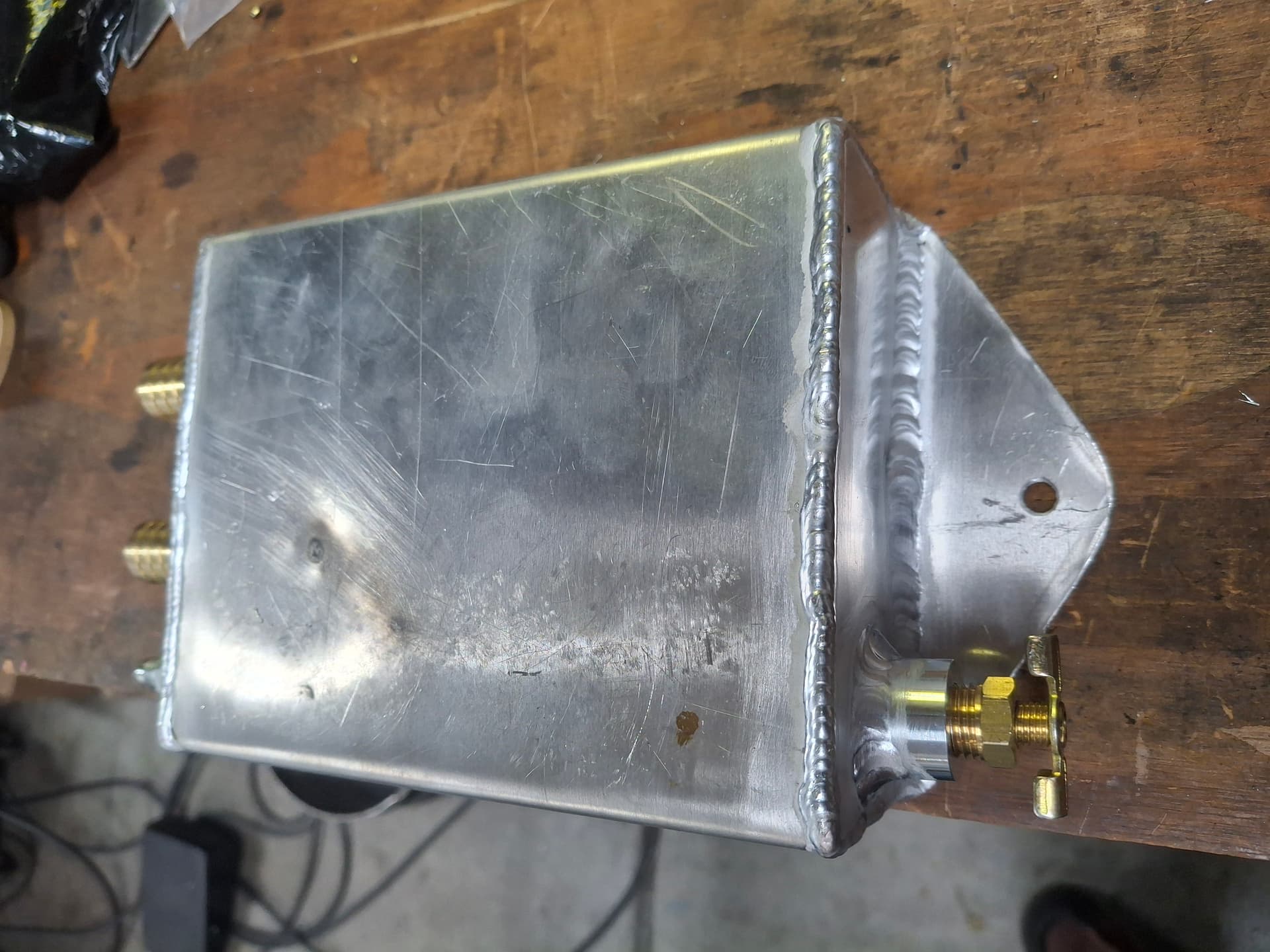
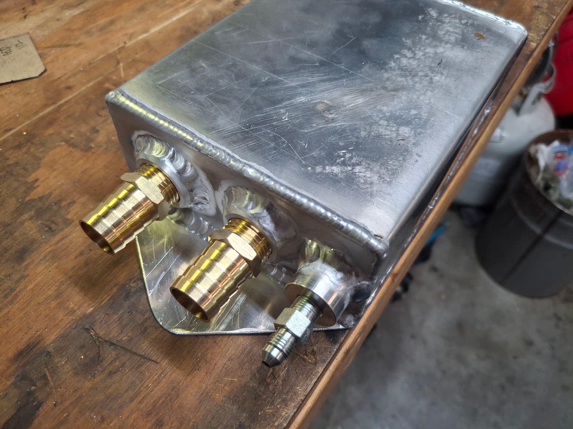
My issues with the Beach’s oil tank and those like is that the tank doesn’t help drop oil out of suspension and then breaths oil vapors at the front of the engine inevitably covering the engine, transaxle, and chassis in oil residue over time and depending on the amount of blow-by; the tank is not easily drained, and the aesthetics don’t do it for me because I’m a prude. :rofl: To add my tale to this larger FV puke can novel, I built a tank from 0.064" aluminum sheet tucked neatly into the corner up against the firewall with plenty of clearance for the generator pulley and belt.

Now for the rules. The 1972 GCR mandates a 1-quart minimum tank for the engine breather system, a separate 1-quart minimum tank for the transaxle breather system, or a 2-quart minimum tank if both engine and transaxle share the tank. To further complicate things, I received clarification from a number of vintage FV drivers from across the country who say SCCA mandates tanks for both the engine and transaxle but that a single 1-quart tank shared by both is acceptable. Considering all these variables, I decided on a single 1-quart tank shared by the engine and transaxle.

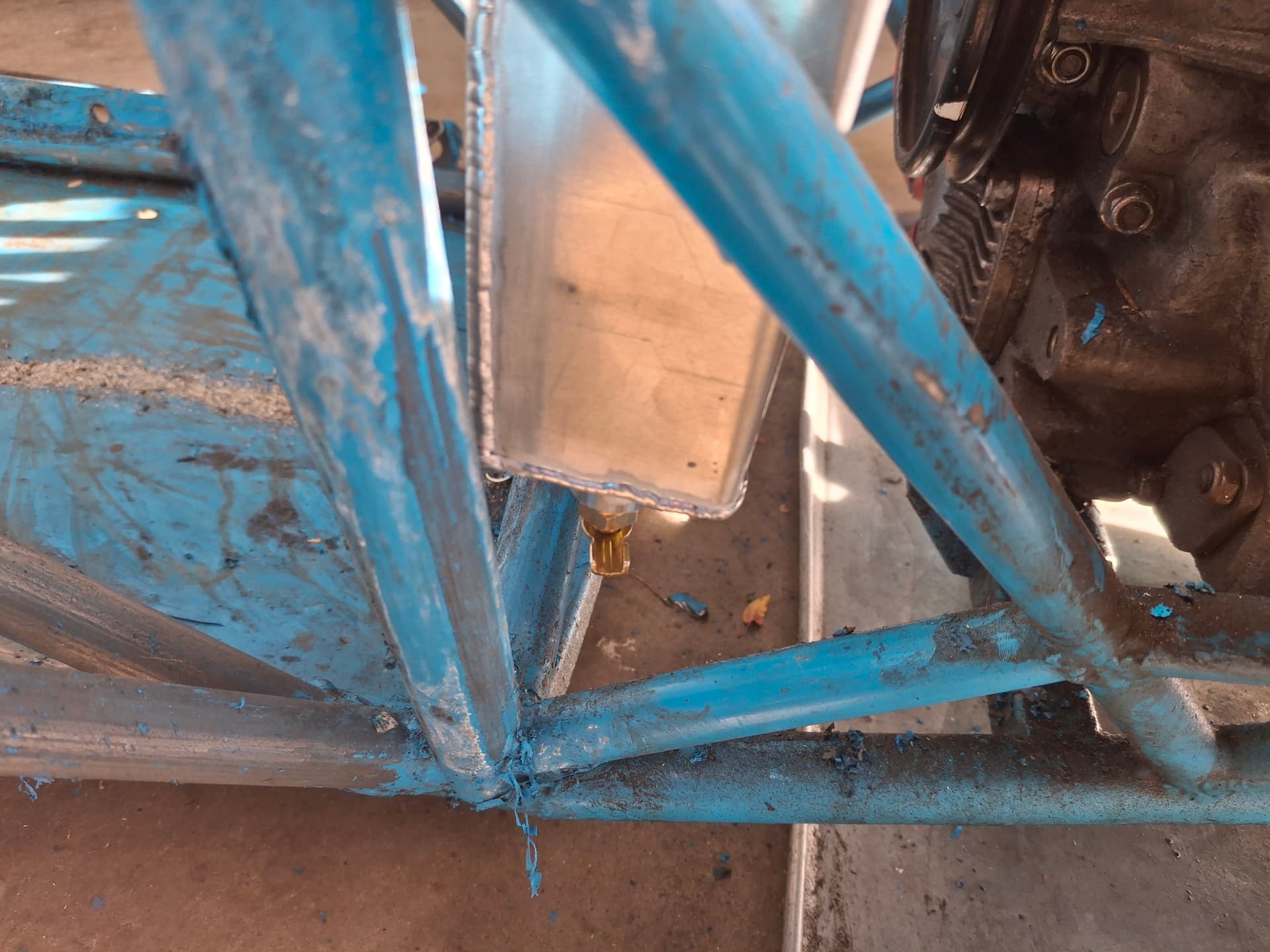
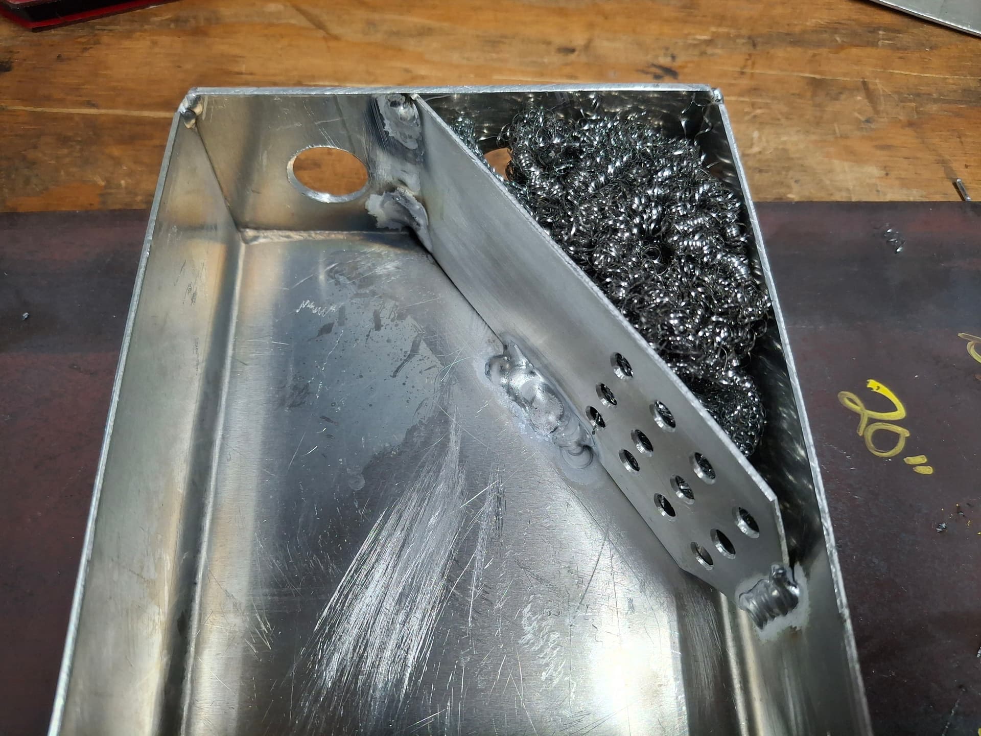
The tank features a 1/2" NPT-to-3/4" barb intake for the engine, a 1/8" NPT-to-3 AN intake for the transaxle, a 1/2" NPT-to-3/4" barb exhaust for the atmosphere vent, and a 1/4" NPT petcock for drainage. Since the breather system is unrestricted by the rules, I increased the tubing from what was 5/8" to 3/4" to assist with airflow, although the factory breather port is the pinch point of 5/8". I adapted that 5/8" straight barb on the breather to a 3/4" barb elbow, and a 3/4" hose carries the oil vapors into the top of the tank. To assist with dropping as much oil out of suspension as possible before venting to atmosphere, I incorporated a baffle in the tank that directs the bulk of the air down aside from what sneaks through the cracks. I loosely packed the intake chamber with stainless-steel kitchen scrub pads that help condense the oil where it then drips into the tank bottom. The air moves down and then up and out of the tank where a 3/4" hose directs it back past the engine and vents to atmosphere inside the airstream created by the front engine cowling fresh-air opening.

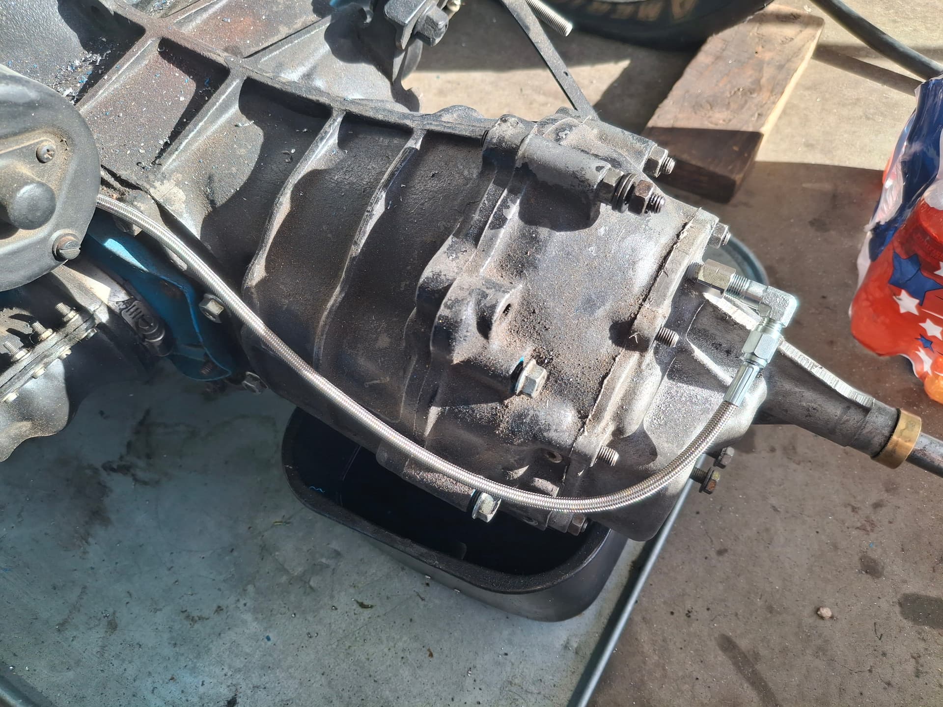
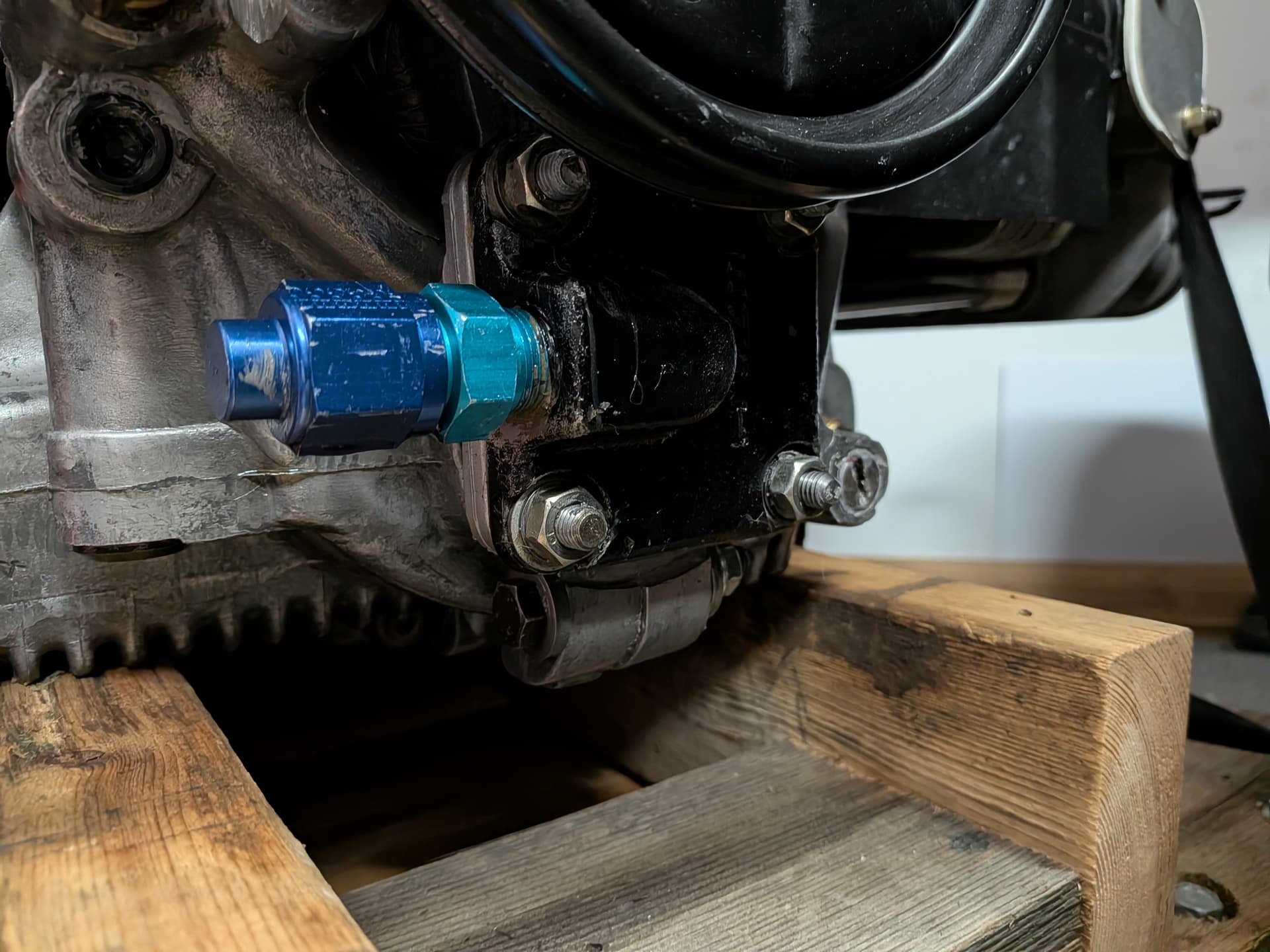
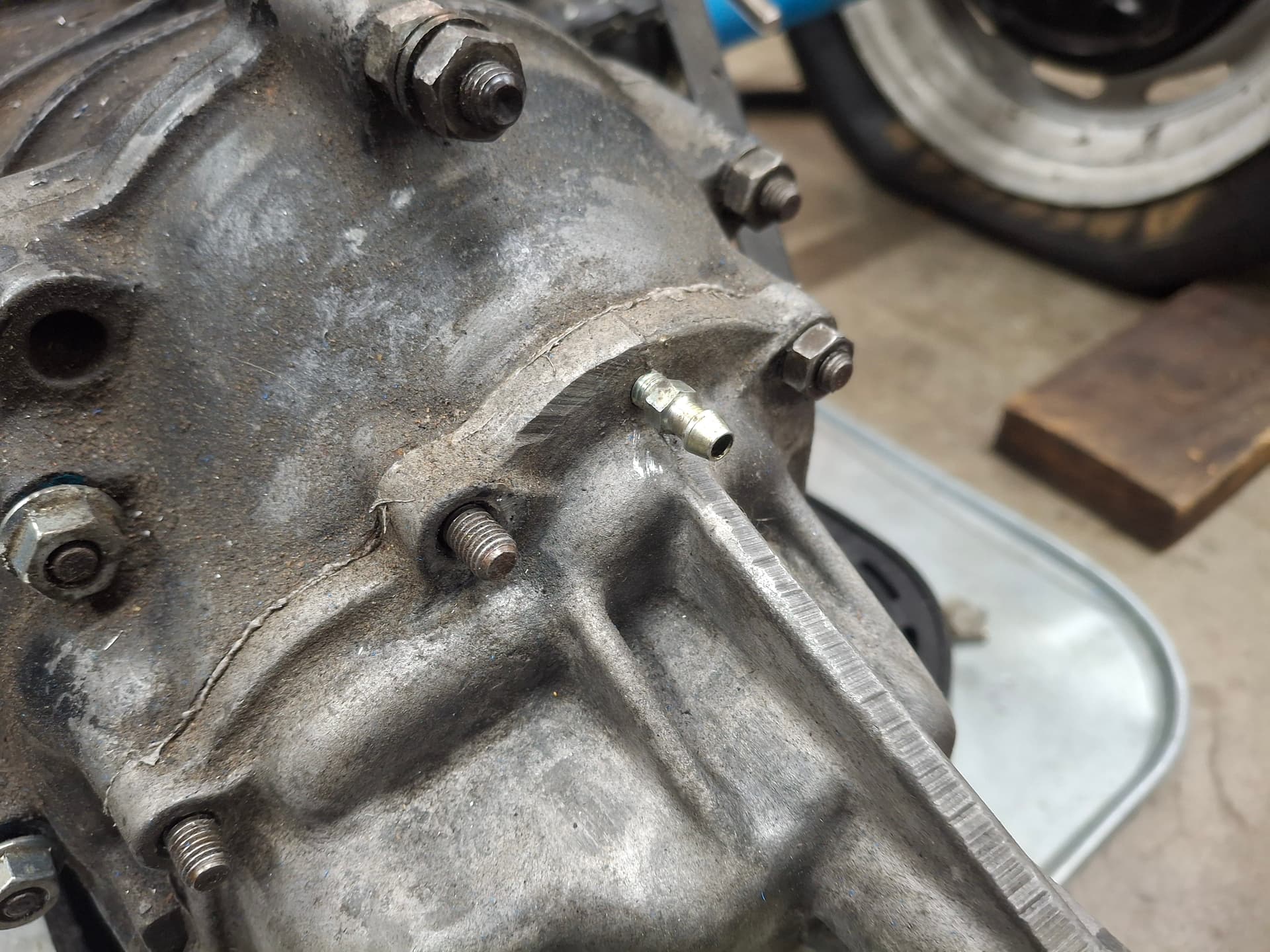
The transaxle originally had what I think was a brake bleeder fitting screwed into the shifter housing. Interesting, this vent was no vent at all because the cover gasket was installed and siliconed in such a way as to completely block the vent hole. A loosely fitted piece of yellowed-clear hose ran from that fitting into a hole drilled in the water bottle oil catch tank. I removed the fitting and hose and adapted to a -3 AN elbow where a -3 AN PTFE braided hose carries the transaxle vapors up to the 1/8" NPT intake port in the catch tank. My understanding is that if the transaxle is properly filled (as in not overfilled), there shouldn’t be any oil venting, but the system is now cleaned up and ready for any vapors should they appear.

Once I remove the engine and have room to work, I will weld upper and lower mounting tabs onto the new firewall. The tank will get painted prior to installation.

Post Alert:
@jonUU
@Sportsracer
@Datsun78
@Bob_Alder
@Rich
@Nick_H
@jackson_prime101
@Raybob9289
@GeorgeCurl
@dreimol
@berck
Justin
A well thought out and fabricated catch tank! A nice addition towards making the car yours.

I hope you have better luck with your transaxle vent hose than me. I’ve broken at least 5 copper tubes over the years. I’ve resorted to a vinyl hose with copper tubing inside so it retains the curly Q shape.

1 Like

Team lacquer thinner can here:) My Zink actually has a really fancy one that Jess made.

While the transaxle will not vent oil, it absolutely vents air as it heats up.

Yours is beautiful, but just to set FV expectations: after your first track session the entire engine is going to be coated in oil mist anyway. Wait until you see the “oil seal” at the front of the crank…

1 Like

Thanks, @berck, lol. Yeah, the apparently impossible expectation of a remotely clean engine is going to really take some serious getting used to. At least the catch tank will be ruled out as the culprit, hopefully.

Remote Oil Filter System

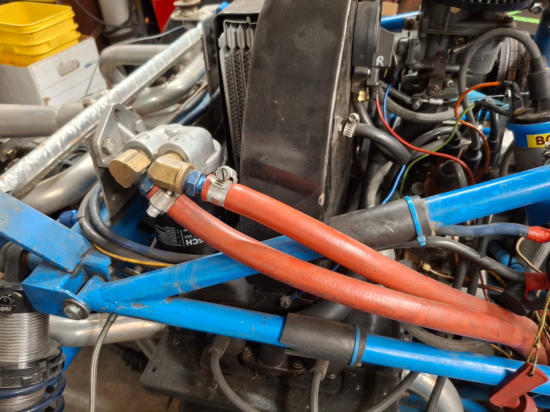
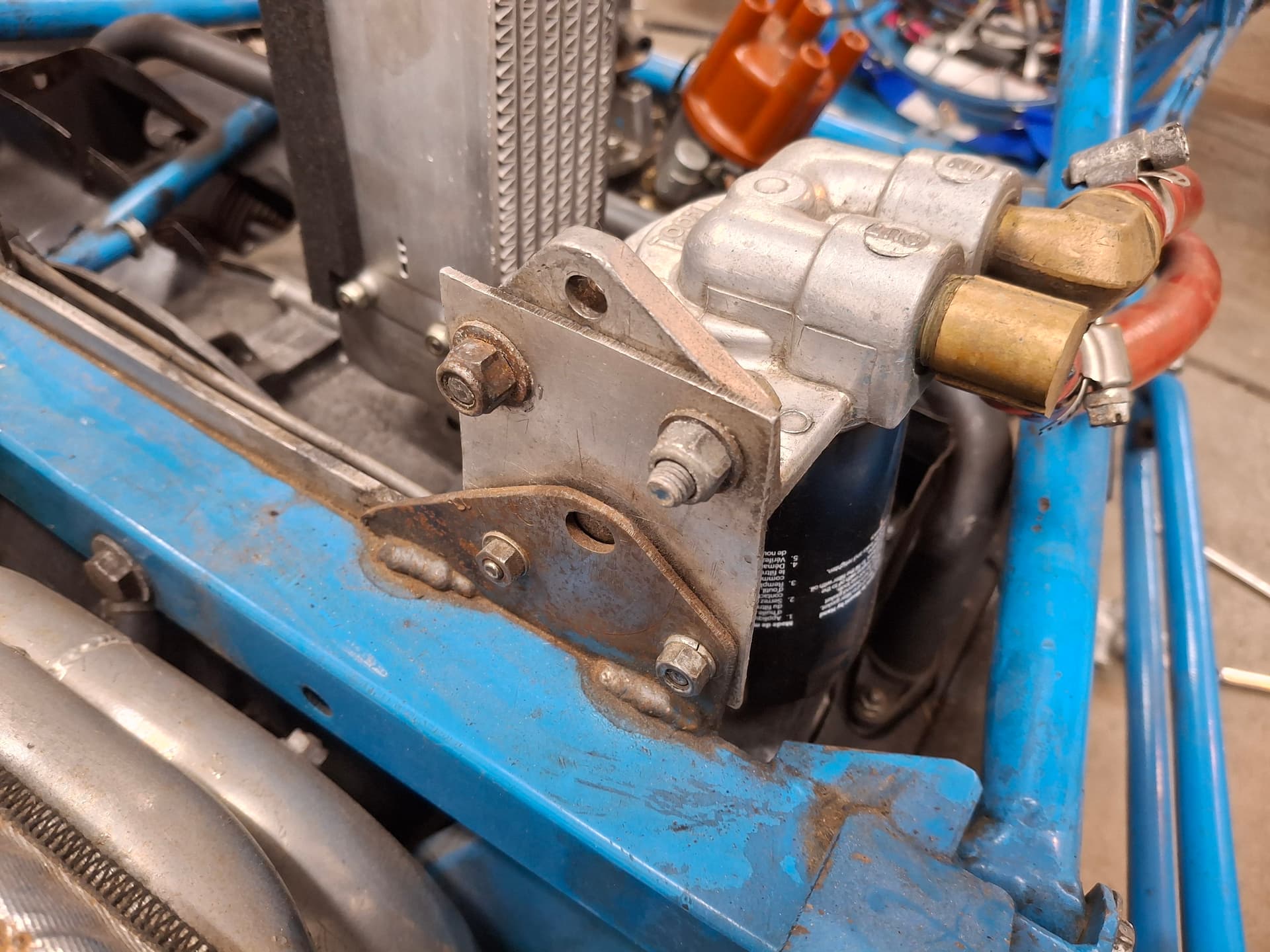
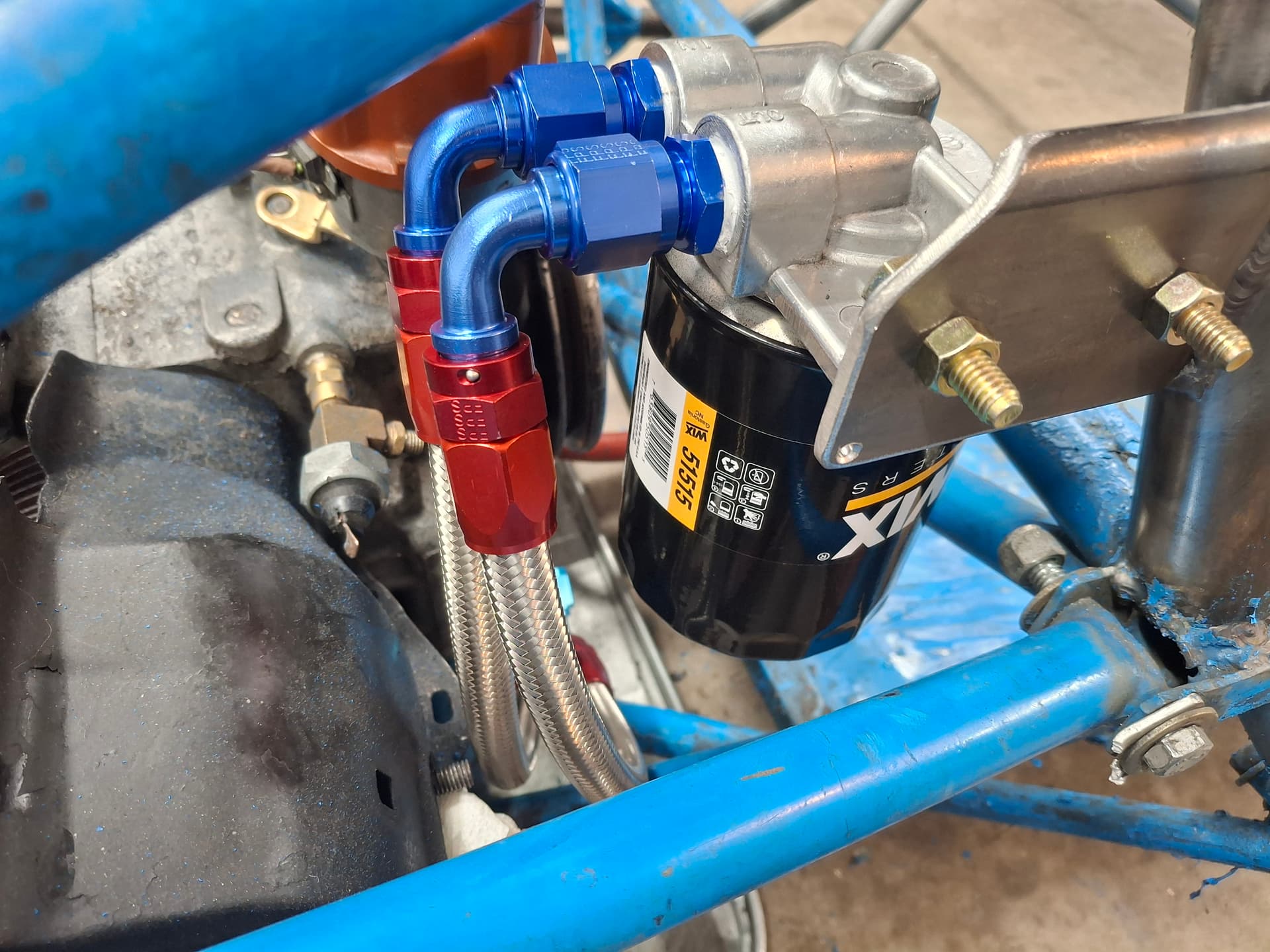
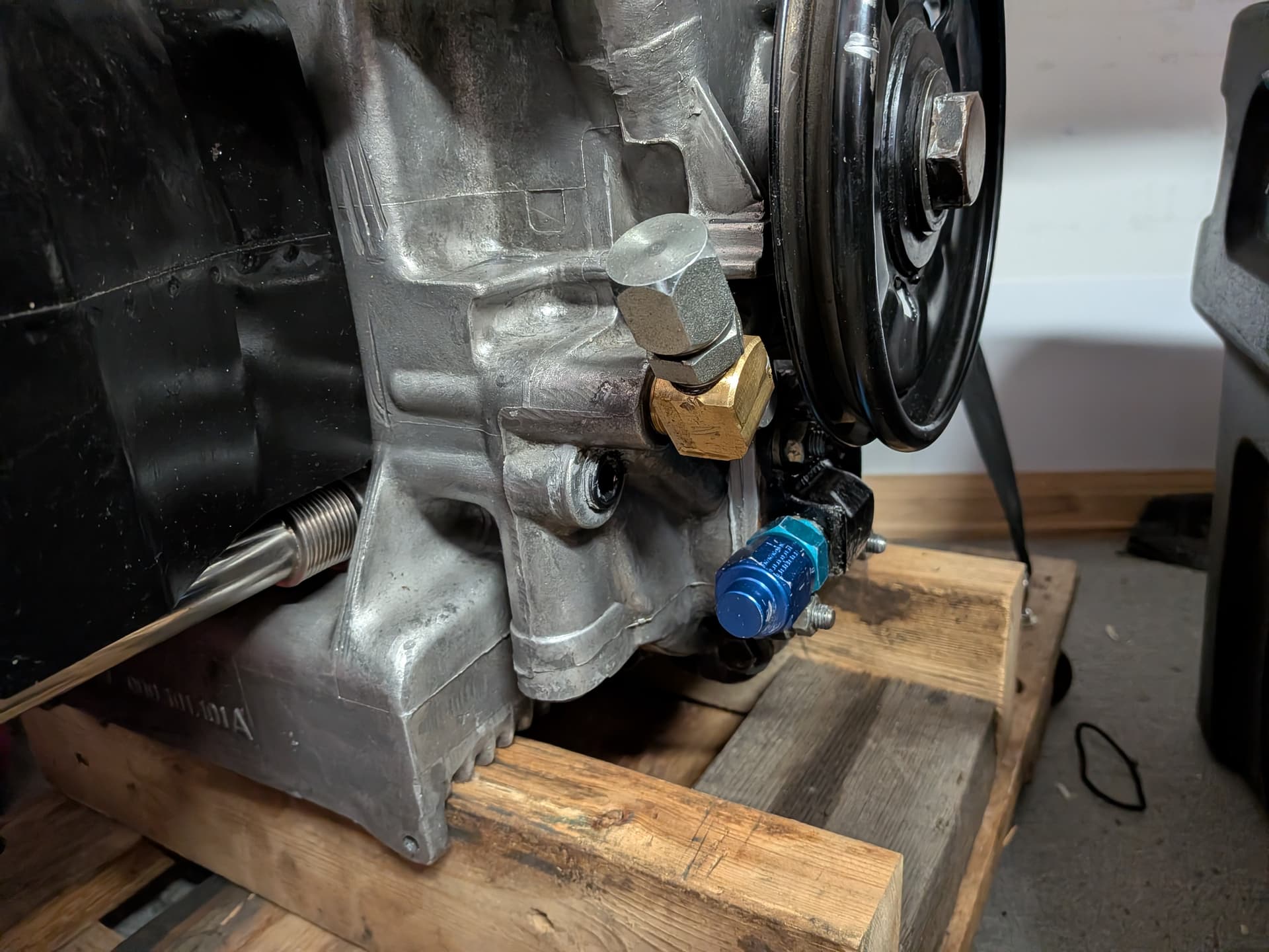
I finished fabricating the remote oil filter system this evening. The old filter adapter was mounted very high up to an aluminum bracket mounted to a steel bracket welded to the rear crossmember that placed the filter directly above the cylinder head. This location must have been a pain to change the filter without spilling oil all over the fan shroud and head, and it limited the size of the filter. The hoses were 5/8" rubber with smooth hose barbs and hose clamps, which I don’t like for a pressurized oil system at 50+ psi.

I removed the old system including the steel bracket that was not original to the rear crossmember. I moved the filter in front of the engine in a location where it lowered the center of gravity and to where changing the filter will drip oil straight down into a pan and over only a couple chassis tubes for easy cleanup. To do so, I needed a different filter adapter fitting layout. After digging through some spare parts, I found exactly what I needed. I cut and drilled a 3/16" plate, scribed it to the roll bar, and welded it in place. This location also lets me use the same 1-quart filter that I use for the Barracuda to cut down on needing different filters, which also meets the Formula Vee Monoposto rule of 1-quart filter maximum.

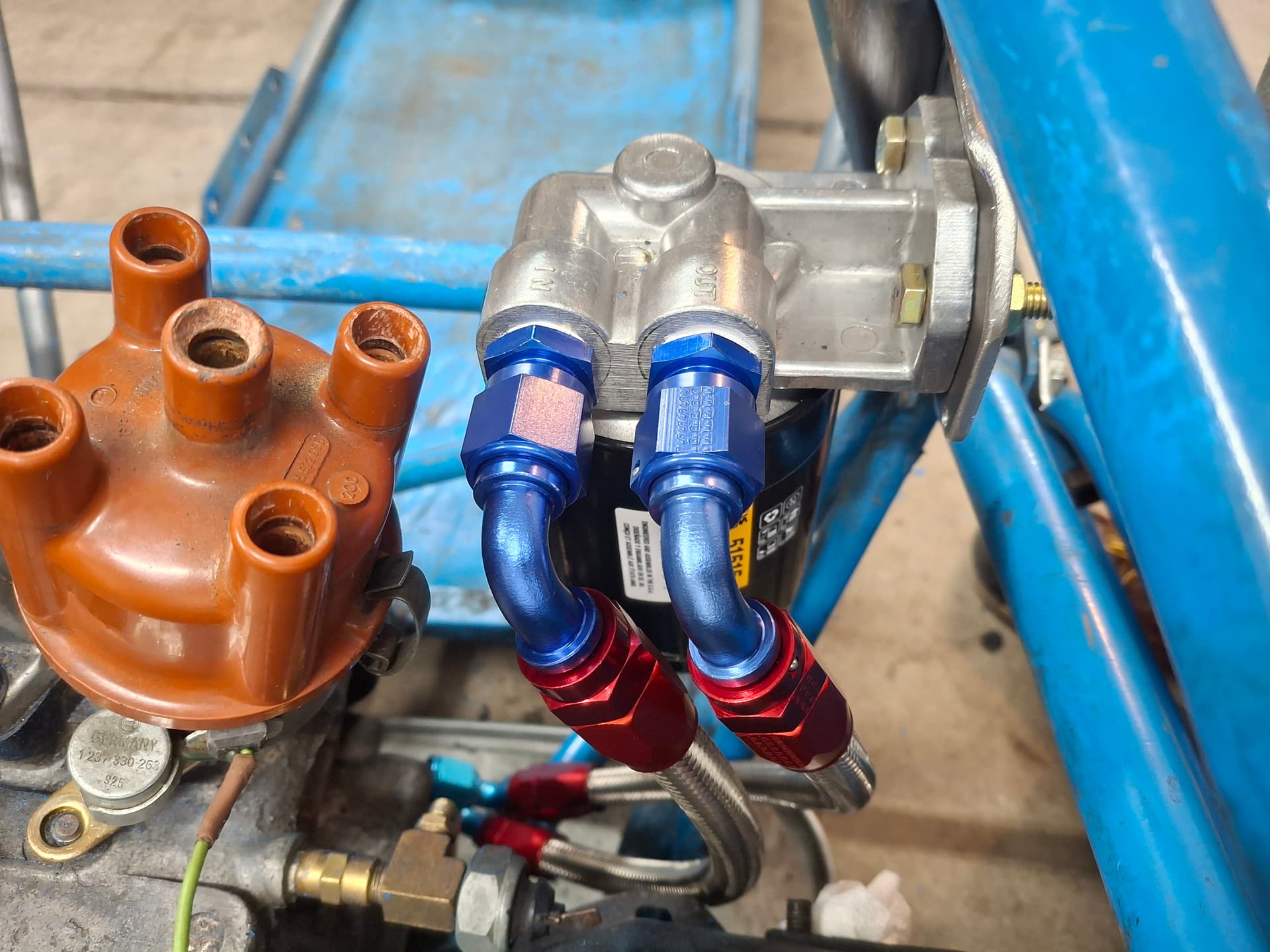
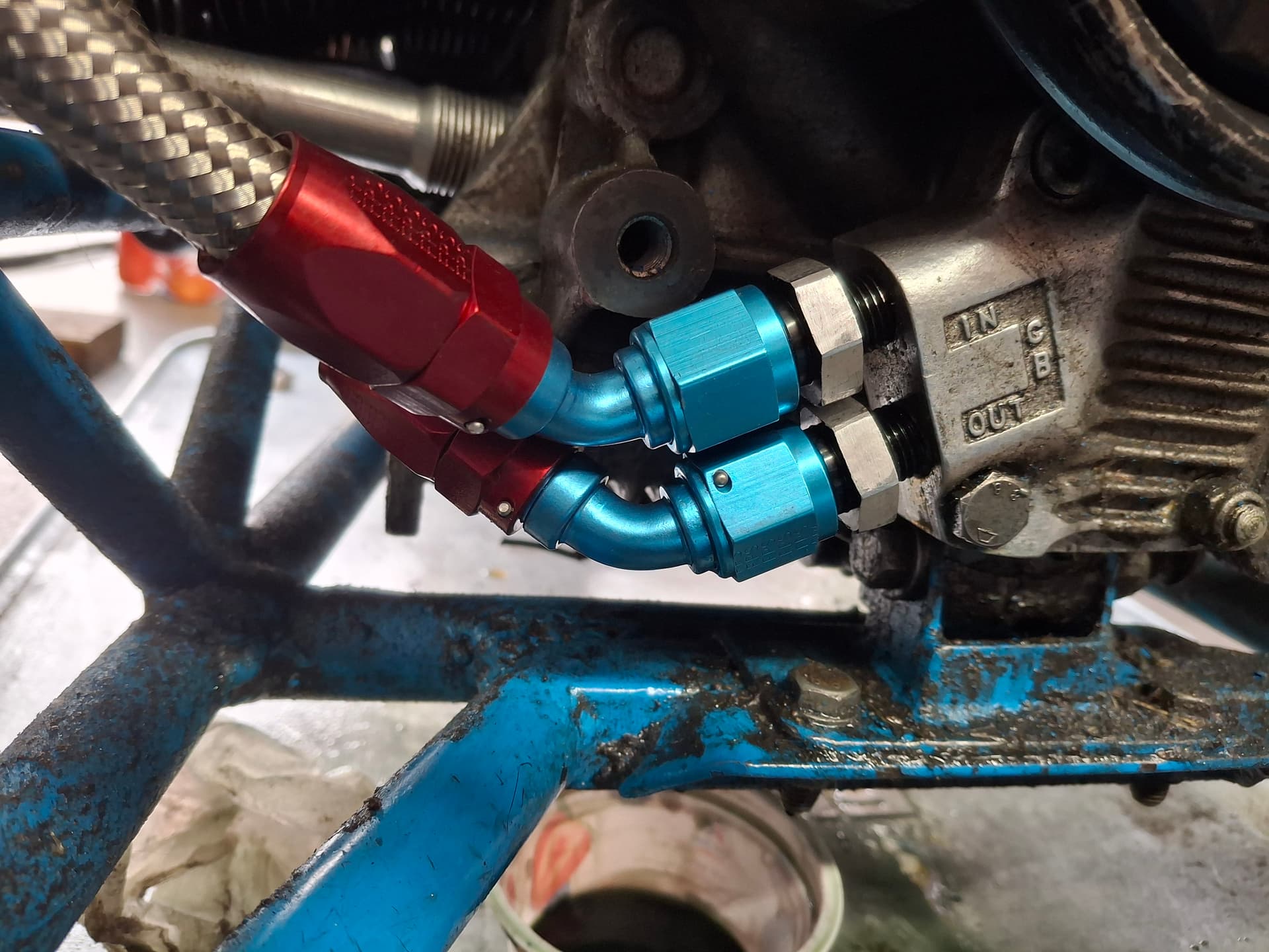
Now for the plumbing struggle, since nothing can ever be easy on a race car. I wanted to use -8 AN braided stainless hose and fittings to take advantage of all the volume, which Jess Valentine confirmed was the size to use. The filter adapter uses 3/8" NPT ports spaced wide apart, so that was a simple pair of 3/8" NPT-to-8 AN adapters. The aftermarket VW oil pump adapter cover, however, uses 1/4" NPT that are annoyingly spaced very close together. The brass 1/4" NPT-to-5/8" hose barb fittings I inherited had 9/16" hex heads that fit the tight port layout. -6 AN would likely be a bolt-on, but not -8 AN. There isn’t enough meat in the cover around the ports to drill and tap them to 3/8" NPT. Porting out the holes farther to the sides and welding 3/8" NPT bungs onto the cover is an option. 1/4" NPT-to-8 AN adapters are the next option, but the issue was they use a 15/16" hex head where I could install one, but the second hit the first and wouldn’t install.

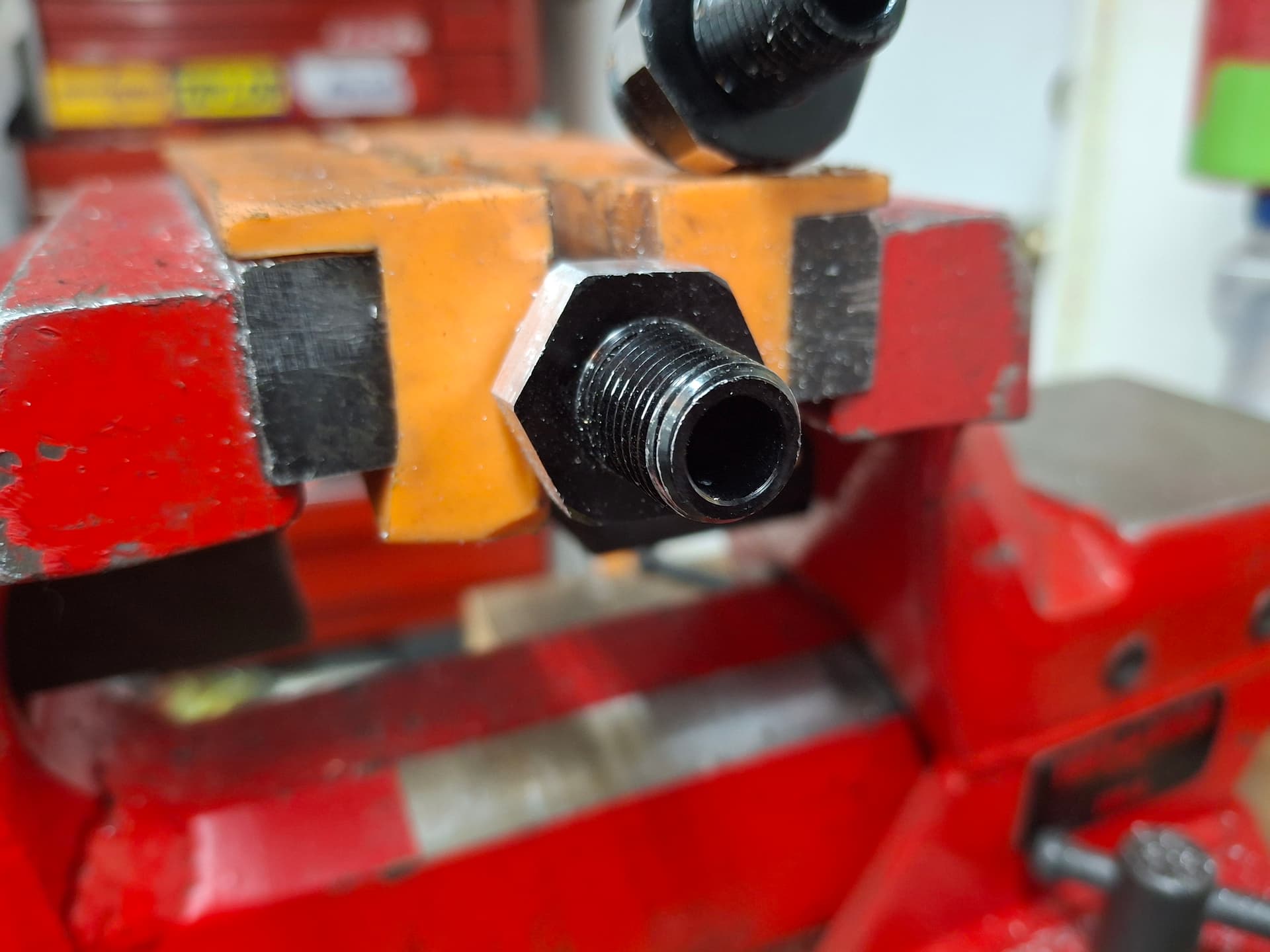
To address the oil pump cover fittings, I filed down the adapter hexes from 15/16" to 7/8", providing just enough clearance to install them. At the pump, I used 60° hose ends to give the fitting enough clearance and to make the bend up before the header tube, and the filter adapter got 90° ends. To stay with the vintage appearance for aluminum hose ends, I went with red and blue. The pump cover situation bugs me still since I don’t have a full -8 diameter with the 1/4" NPT adapter, but it’s still larger than -6. I can’t find a cover that uses 3/8" NPT, so unless I want to weld on this one, I’m stuck with the 1/4" NPT. At the end of the day, it’s likely a nonstarter for impacting oil pressure since I assume all other FVs with a remove filter are stuck with this cover.

Post Alert:
@jonUU
@Sportsracer
@Datsun78
@Bob_Alder
@Rich
@Nick_H
@jackson_prime101
@Raybob9289
@GeorgeCurl
@dreimol
@berck
Justin I like your solution to file the fittings at the oil pump. Another thought for the future might be to extend one fitting so the hex areas are not in alignment. I have cut, turned fittings in the lathe to make a fitting for a tight area and then welded them together. Sometimes it means using 2or 3 fittings to make one, and we all know AN fittings aren’t cheap, but necessity dictates our path at times.

Anyway it looks like you’re making good progress on the restoration. I can’t wait to see the finished result.

Tom

1 Like

There are better styles of full-flow oil pump covers. My engines all have a single 3/8 NPT fitting on the outlet for the oil pump cover, then a 3/8 NPT fitting for the oil return that goes straight back to one of the galley plugs on the case instead of the oil pump. 3/8, not 1/4, and none of this filing fittings nonsense needed.

1 Like

@berck, would you please link to the cover you’re using and post a photo of where the return goes into the block? I’d appreciate it. I’d certainly prefer a full -8 system over pinching to what would be a -7, if you will.

Here’s the photos from one of my spare engines. This is how Jess configures engines he’s built for me, so I’ve never acquired the parts myself. I’d ask Jess for his preference but I think it’s readily available stuff. ACC-C10-5390 - 9226 - FULL FLOW OIL PUMP COVER W/ SINGLE OUTLET - ALUMINUM - SOLD EACH

Thanks, @berck. That block port on mine still has the soft expansion plug, so I assume Jess and I will tap it during the rebuild. That’ll be a clean place to tie into the system where my filter is located. It looks like your cover is a cast-iron piece by EMPI, so I’ll check with Jess if he prefers the iron or cheaper aluminum cover. I assume iron, which is what I prefer, since the pump gears can ride against it. Thanks again!

Engine Removal and Shifting Issue Diagnosed
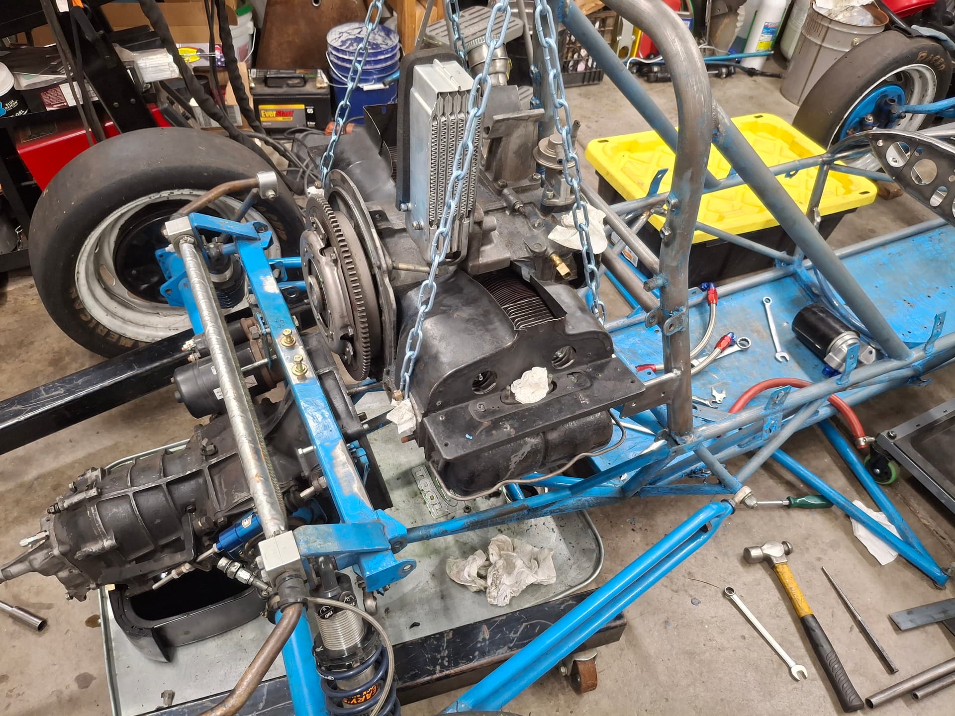
I pulled the engine this past weekend without too much trouble and was able to leave the transaxle in place to assist with rolling the car in and out of the garage to do cutting/grinding. I built a chain system that connects to my cherry picker hoist, which ended up working well.

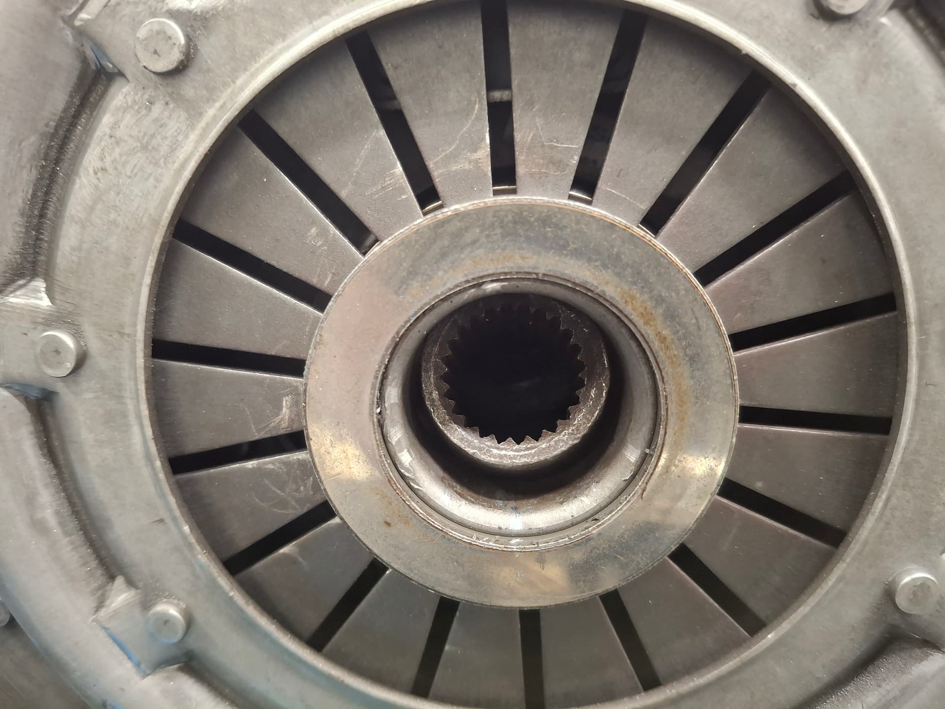
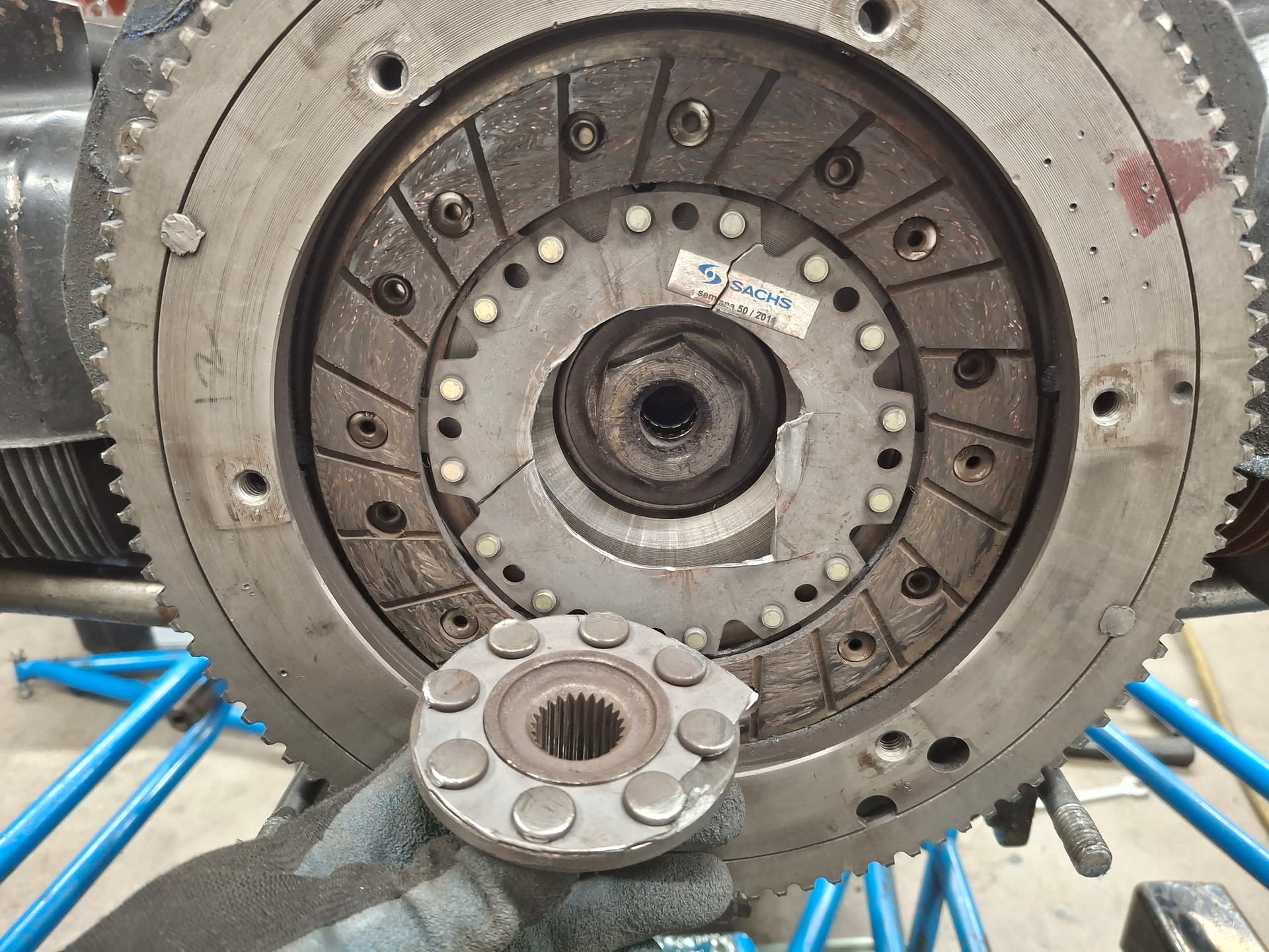
Immediately upon the clutch clearing the bellhousing, I discovered the culprit of what @Nick_H reported as an issue with the transmission. The clutch disc splines were cocked sideways, and after I removed the diagram, I discovered that the spline hub completely tore out of the disc. With the severe fractures, it’s lucky the disc didn’t fragment and send pieces through the bellhousing before the hub completely detached. I’m surprised at the extent of the dame since these things don’t have much torque and aren’t dropping the clutch, but there might have been a harmonics issue. Add a new clutch to the list of needed parts.

Rear Chassis Section
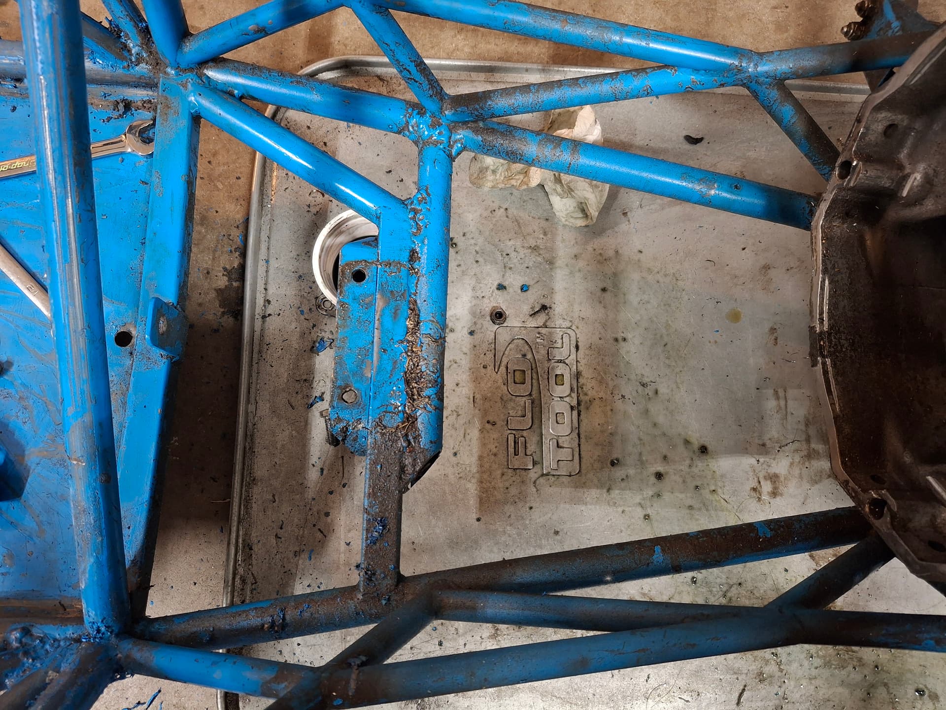
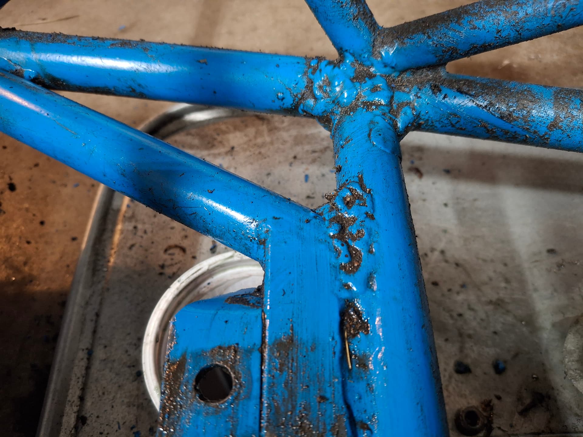
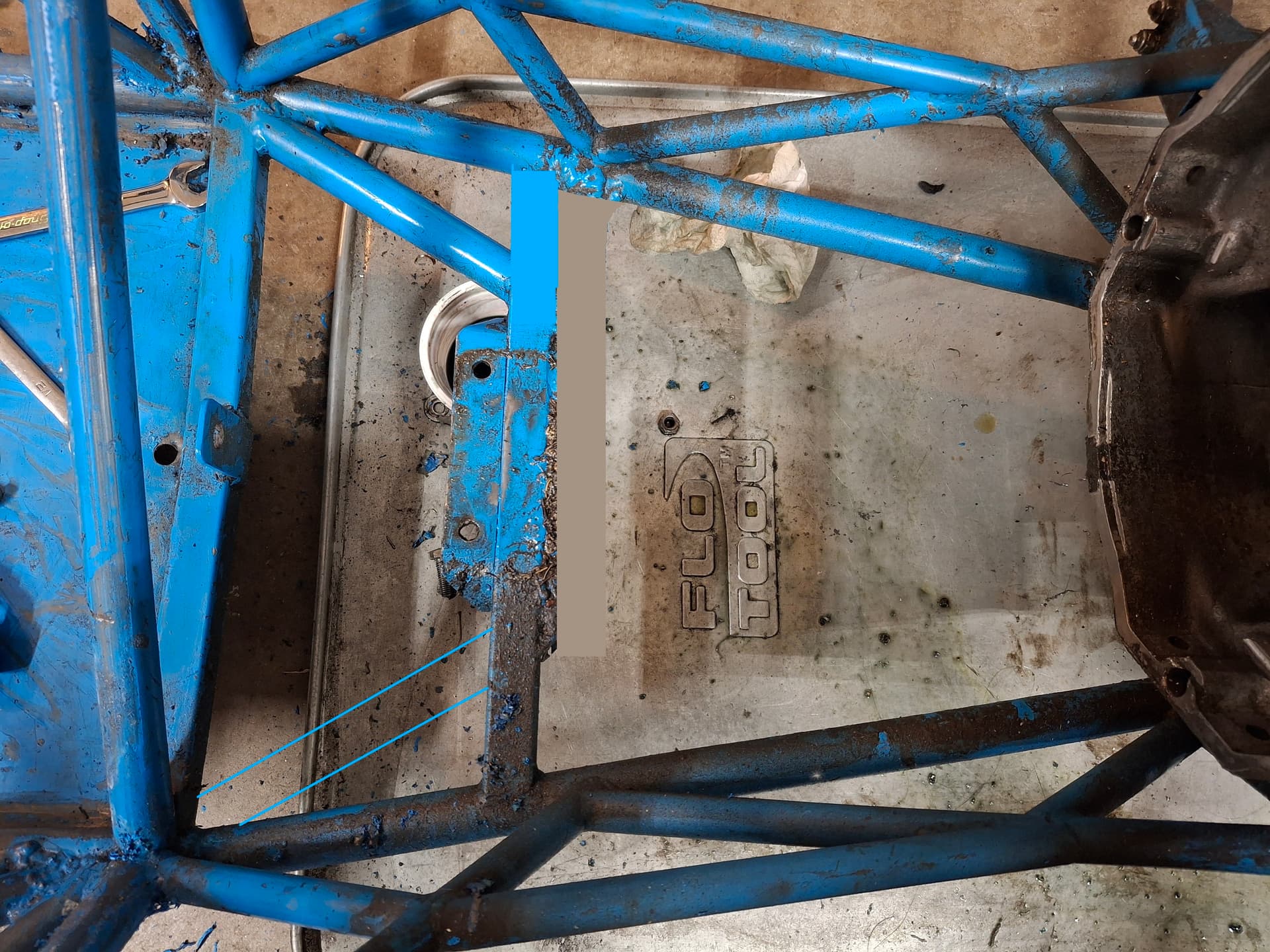
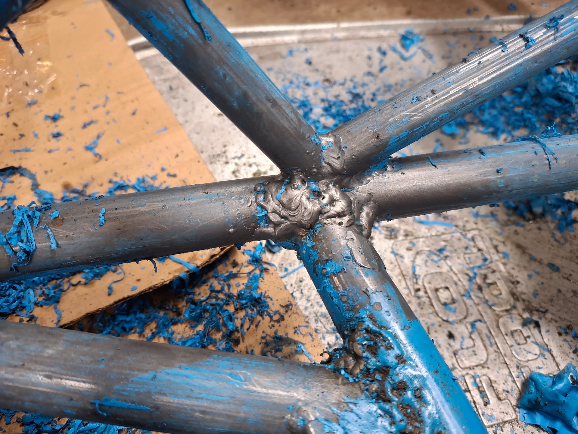
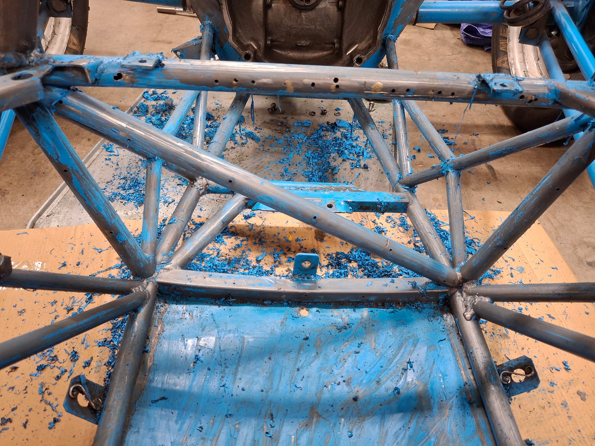
With the engine removed, I noticed some modifications to the engine crossmember that I don’t like and some parts that confuse me. The square crossmember and diagonal round tube are original with TIG welds, and someone scabbed on another piece of round tube with a sharp open end and arc welding applied either too hot or too cold. I don’t understand why they didn’t simply butt a short piece from the crossmember over to the frame rail, but I wasn’t there to suggest that.

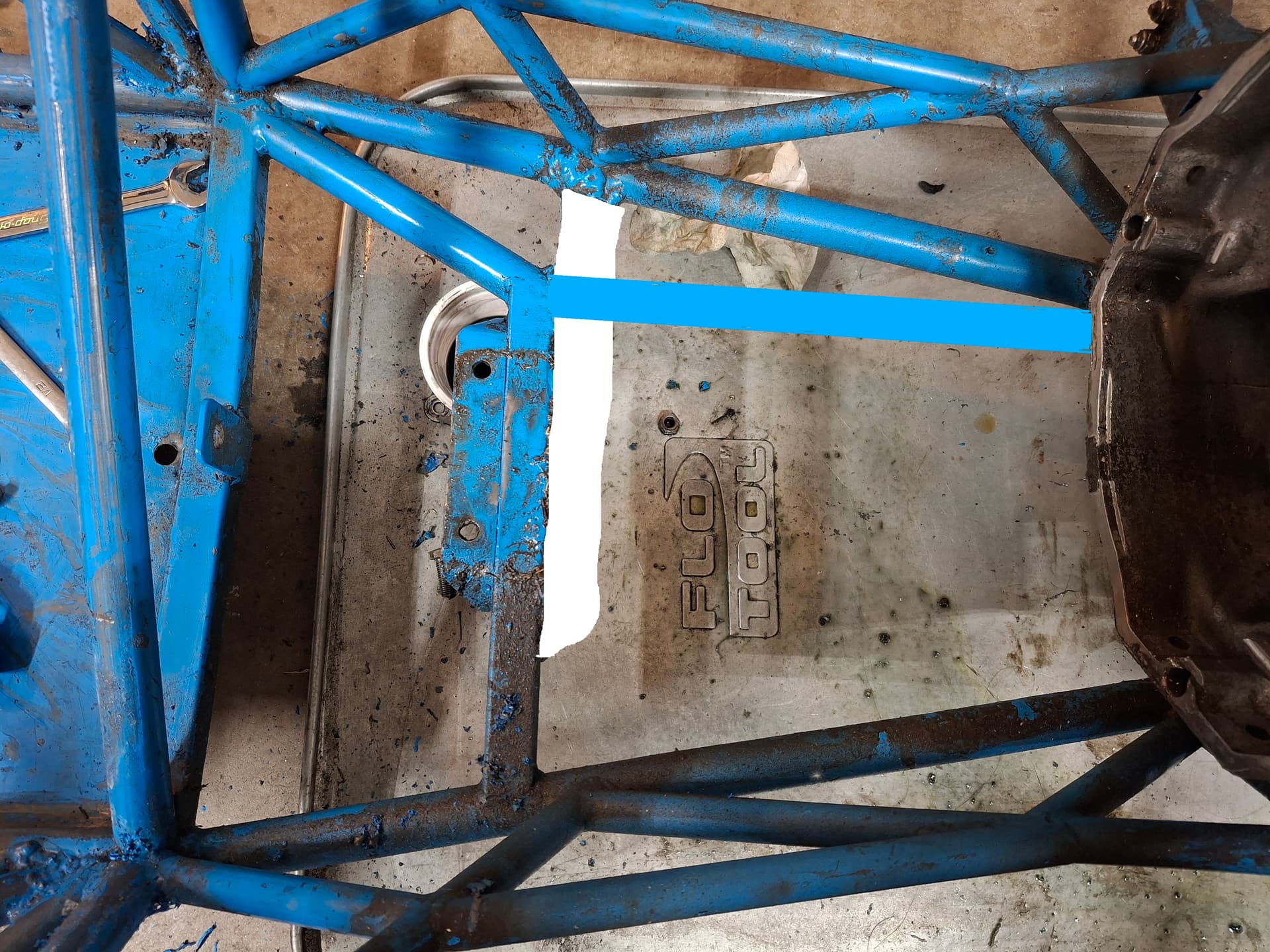
While Mk5C chassis photos of this area with the engine removed are rare, I found two that show a configuration where the square crossmember runs from the left frame rail and terminates into a triangle formed by two diagonal round tubes. My chassis maintains the front diagonal tube, but there is no indication that there was ever a diagonal tube running from this connection back into the right frame rail, which I’ve added in the following photo for a visual. My best guess as to why Beach didn’t simply run the crossmember from frame rail to frame rail is header clearance, although the current #3 header tube doesn’t come anywhere close to the engine crossmember.

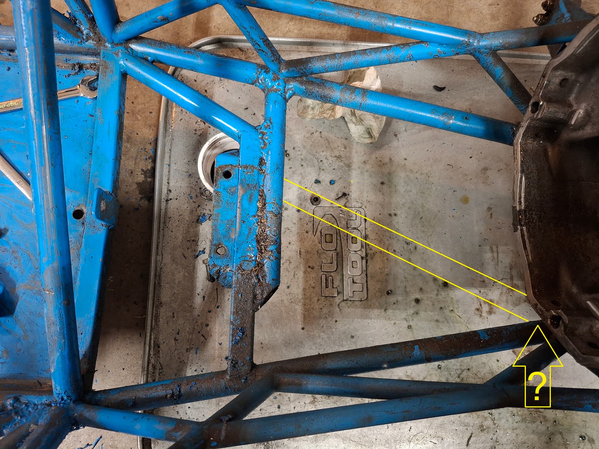
While inspecting the chassis, I found a TIG welded round tube at the left rear corner that had been cut off whose angle appears to have originally run from the left rear corner of the chassis toward about the center of the engine crossmember, which I mark in yellow in the photo below for a visual. This tube would have contacted the oil sump in that configuration unless it bent down into a “U” to where I doubt it connected to the engine crossmember but was used for another purpose. The Mk5C chassis photos I’ve found don’t show any tube in this location, so who knows.

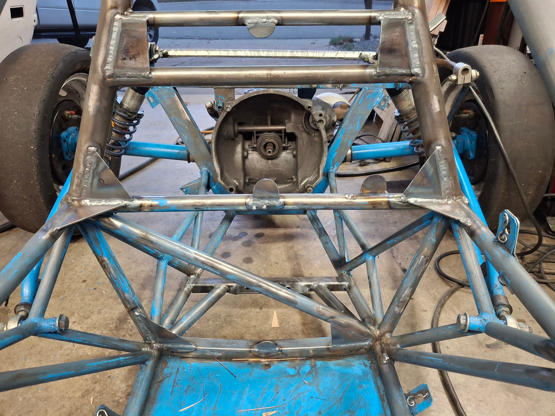
To clean up the mess, I’m going to cut out the entire square crossmember and the added round tube, and I’ll neatly cut the factory diagonal at the crossmember. I’ll fabricate a new square crossmember that will run from the left frame rail to the right frame rail and will tie the factory diagonal into it. For more symmetrical triangulation of the rear section, I may replicate the diagonal on the left side. It’ll look something like this photo:

Post Alert:
@jonUU
@Sportsracer
@Datsun78
@Bob_Alder
@Rich
@Nick_H
@jackson_prime101
@Raybob9289
@GeorgeCurl
@dreimol
@berck
Justin
As haven’t seen your car and don’t know the chassis, is it possible that you can utilize the engine/transaxle assembly as a stressed member and do away with any of the previously added tubes? In the past a lot of manufacturers didn’t consider this as a viable engineering solution.
On my car, during the conversion, I considered the additional strength of the new transaxle to engine connection. The old adaptor utilized 4 bolts to connect to the engine whereas the new one utilizes 9. Yes most likely due to higher horsepower but with this more rigid connection
I eliminated the rear kicker tubes from the roll bar to the rear bulkhead. I added front kicker tubes which provide more driver protection and support the front of the chassis to the front bulkhead. While I didn’t save any weight, the chassis is now more rigid over all.

Just something to consider while you’ve got the car disassembled and you’re cleaning up past modifications.

Engine Crossmember Fabrication
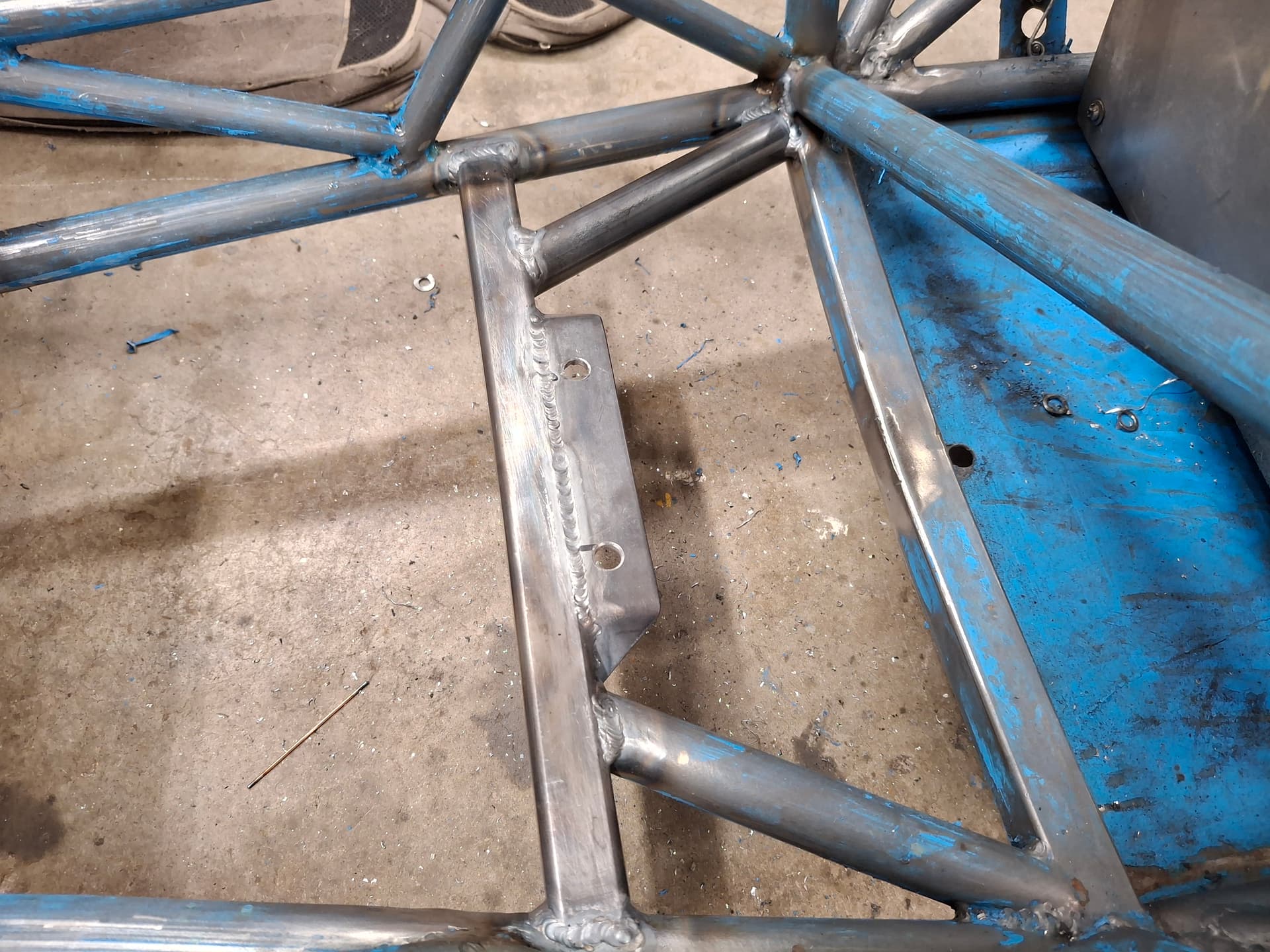
I spent the last few evenings stripping the paint off the rear section of the chassis, cutting out the original crossmember and added round tube, and cleaning up people’s “welds.” I replicated the original crossmember (1" x 1" x 0.120" tubing) and the engine mounting flange, and I added a second 1" round diagonal brace on the left to mirror the right and add more triangulation.

Tom, to your question and suggestion about stretched skin, the 1972 FV rules allow stretched skin only on the floor pan and the firewall. Plate gussets to support chassis connections and for driver safety are exempt.

Post Alert:
@jonUU
@Sportsracer
@Datsun78
@Bob_Alder
@Rich
@Nick_H
@jackson_prime101
@Raybob9289
@GeorgeCurl
@dreimol
@berck
1 Like

You do nice work Justin. I enjoy following your progress.

Nice improvements! The original welds look like what happens when I try to weld:)

Thanks, @jonUU! It’s fun sharing the progress.

@berck, I’m down for some practice welding or a welding project if you need something.

Fuel Cell Rehab
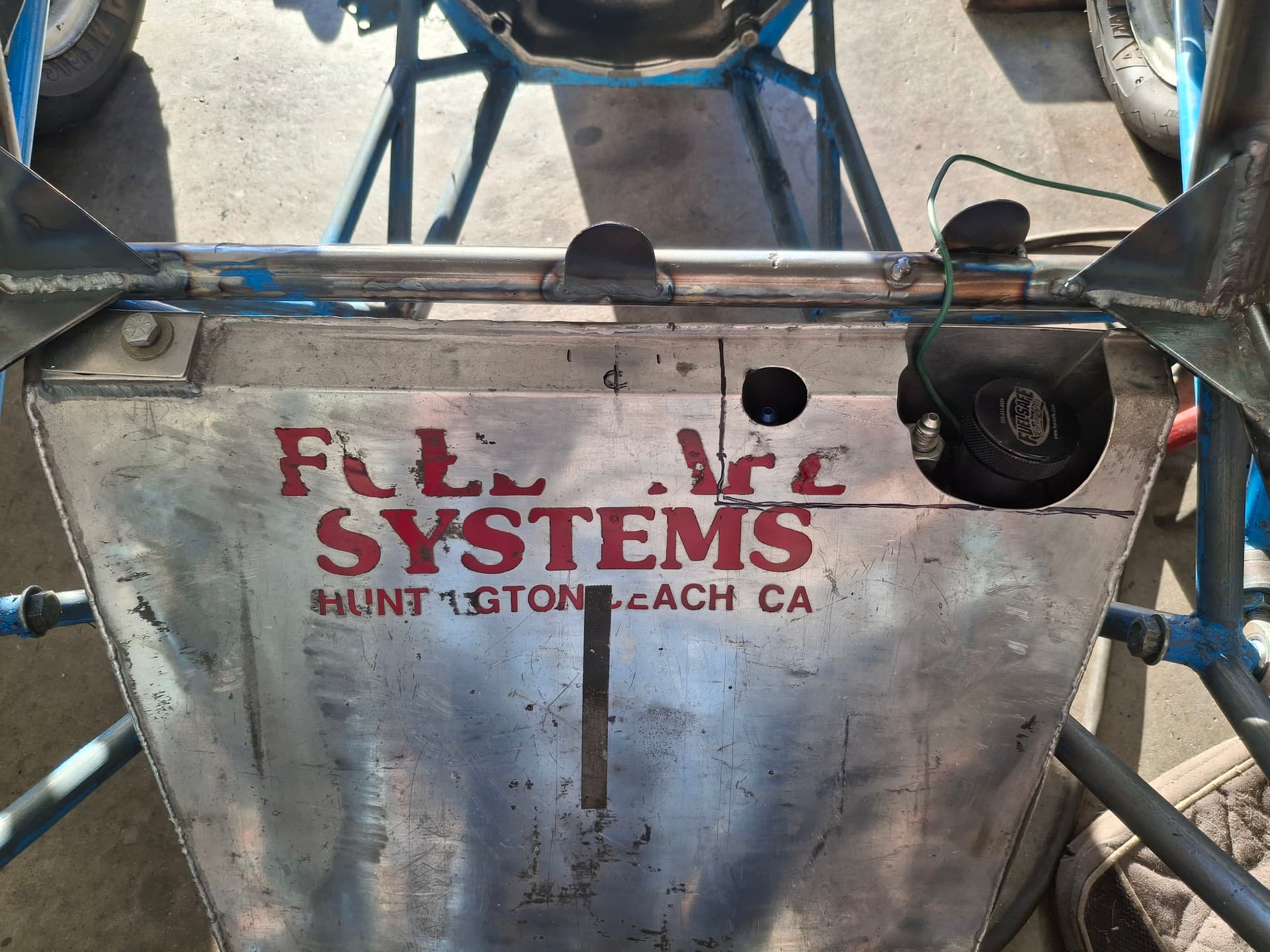
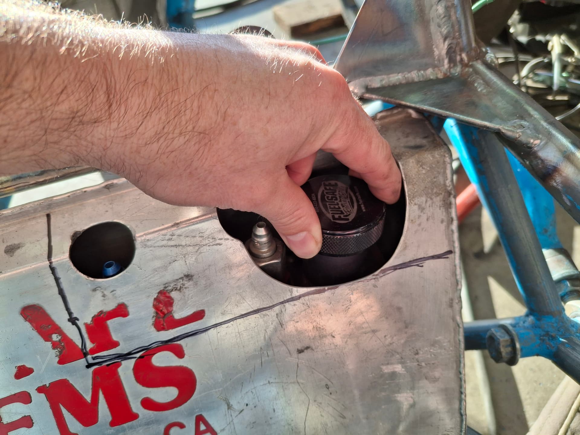
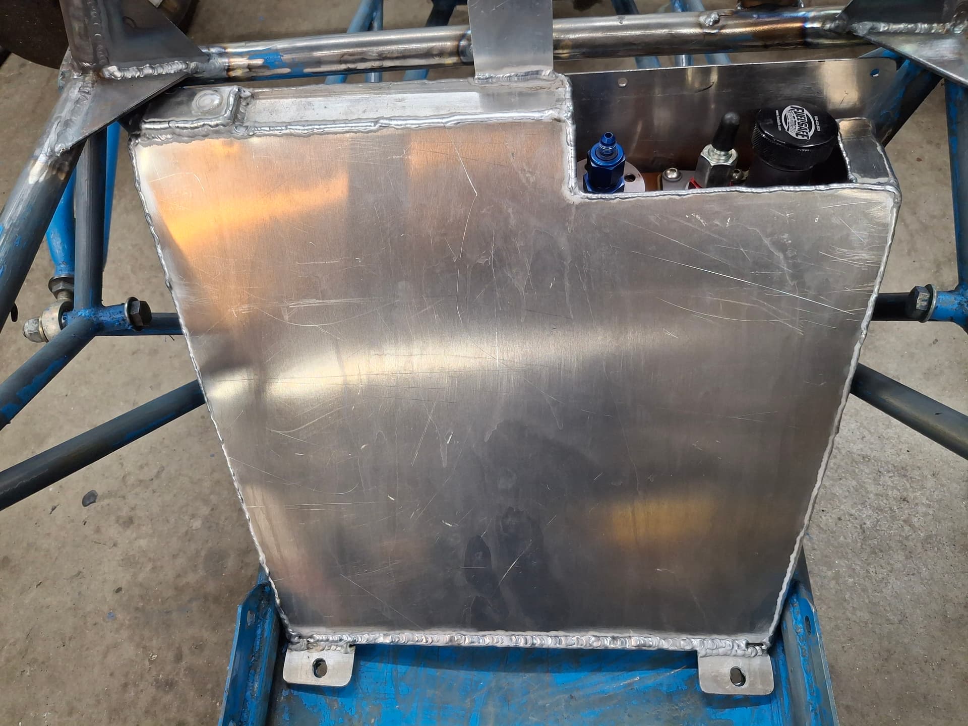
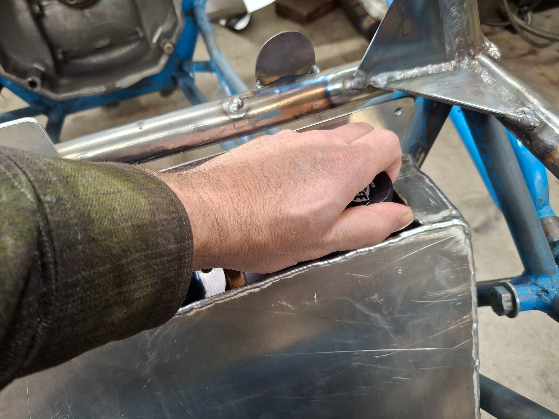
I knew during disassembly that the fuel cell needed some love. What I’ve determined is that the bladder was replaced at some point with a custom Fuel-Safe cloth bladder, so the aluminum housing and bladder weren’t made for each other like a modern Fuel-Safe cell where the filler/outlet plate bolts through the housing into the bladder. While RMVR and GCR rules allow holes in the aluminum housing for fuel/vent lines and the filler neck, the bladder was too low in the housing where getting a wrench on the fuel connections was very difficult, and removing the filler cap was only possible with a few fingers and threatened cuts each time against the aluminum edges.

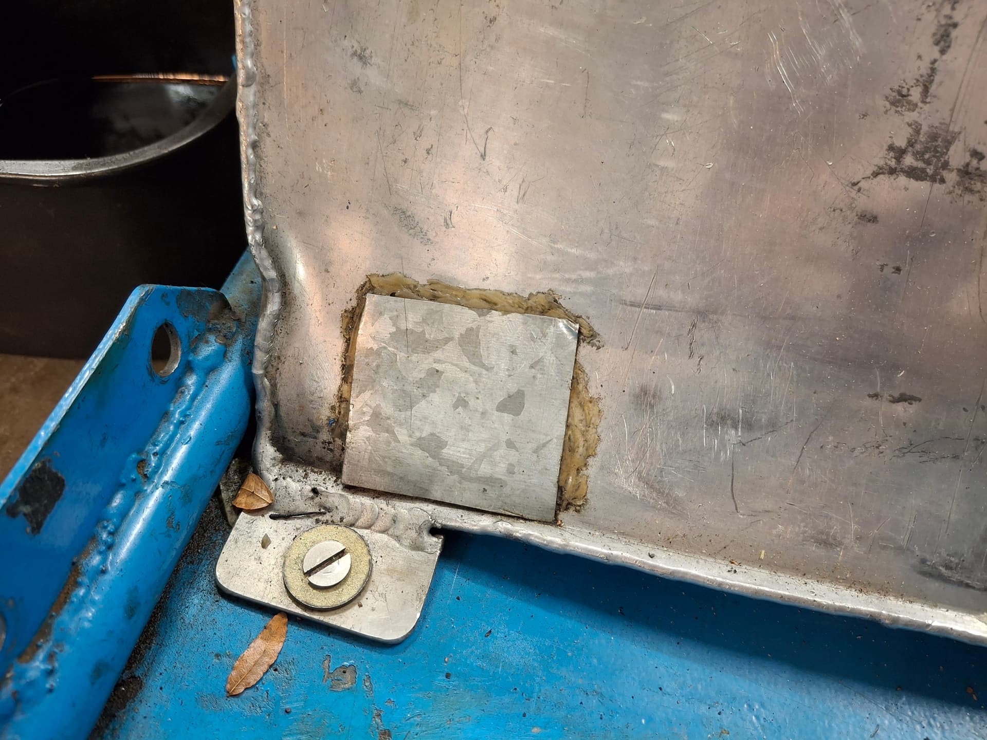
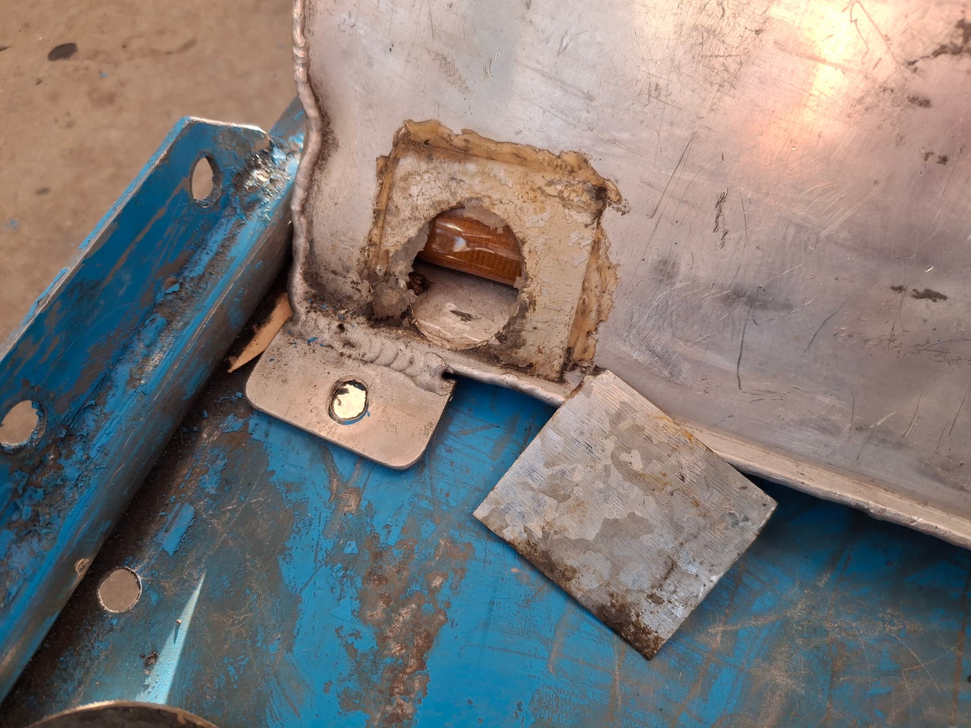
There were other issues too. The housing is made of a softer temper (likely 5052 alloy) lighter gauge aluminum sheet to where years of the driver leaning back against the front plate concaved it badly and cracked multiple welds. The caved-in front panel was also limiting the bladder capacity since it compressed it. Multiple threaded inserts for the housing’s rear access panel were also stripped or torn out completely where the panel was secured in places with electrical tape. There was also a large abandoned fuel line hole in the bottom of the front panel loosely siliconed over with a piece of sheet metal. I didn’t like that since a fuel spill while filling or a bad puncture in the bladder would allow fuel directly onto/under the seat. There was also another abandoned fuel line hole in the top right of the housing with loose plate over it.

Repairs and Improvements
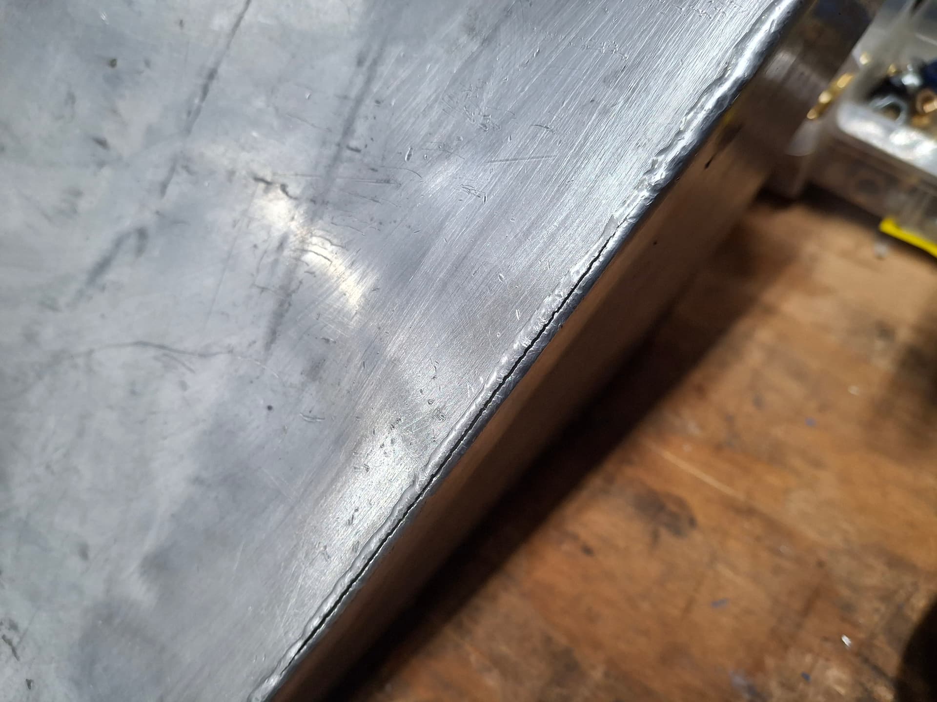
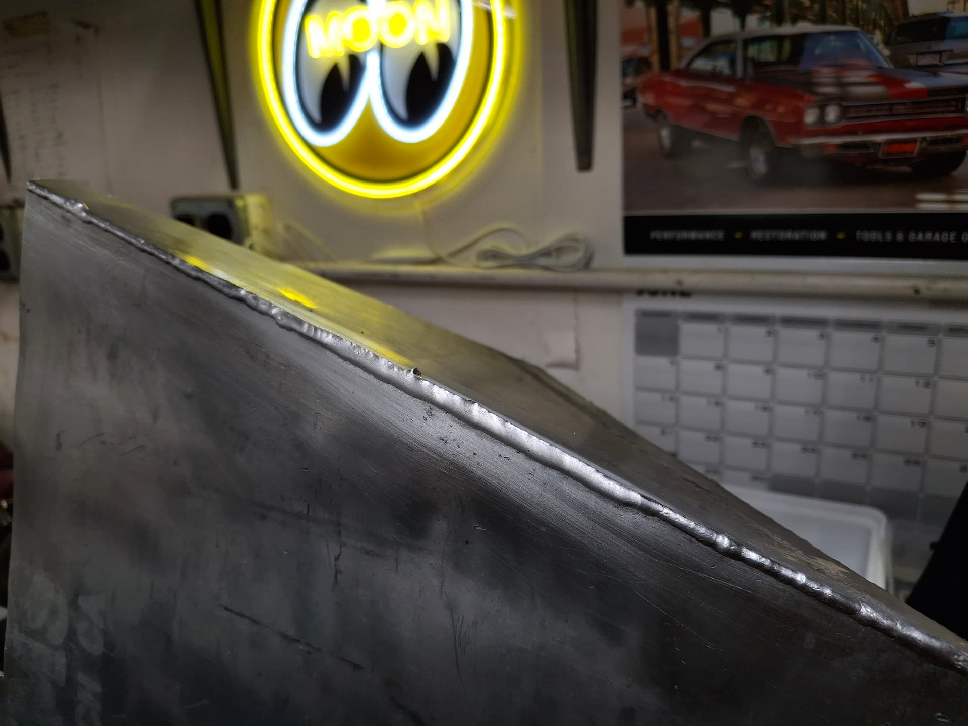
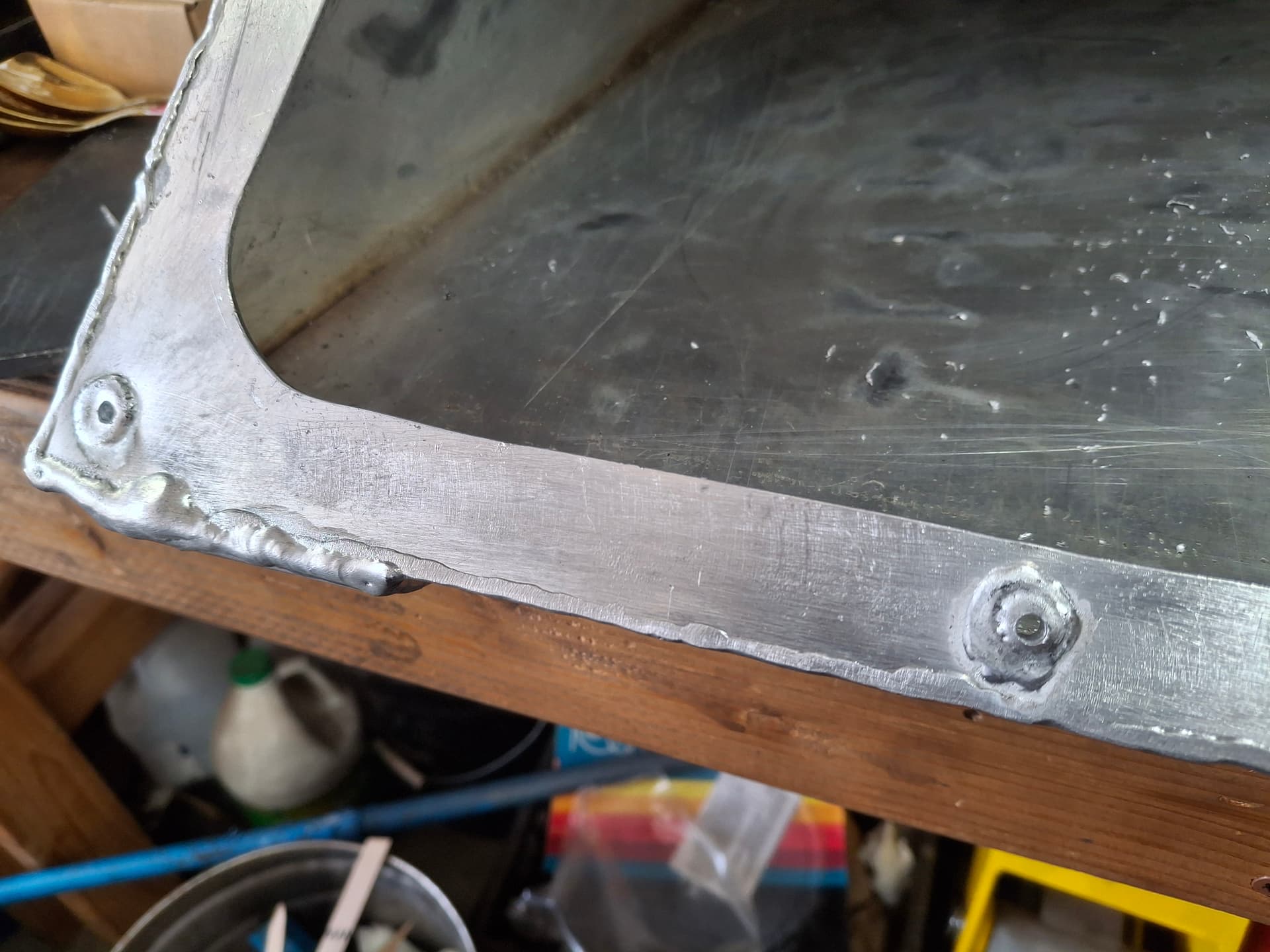
After wire-brushing the welds and scrubbing the housing with degreaser as best I could to clean out all the oil deposits, I did some hammer and dolly work to pop out the front panel and welded up the cracks. I cut down the top of the housing to fit the fuel line/vent/filler setup, boxed the opening, and welded a bead around any sharp edges. I welded patches over the two abandoned holes in the housing and welded a new front panel of stiffer 0.080" 6061 T6 aluminum over the existing panel to create a double-wall, stronger bracing for the seat. I can now press back hard on the housing and it won’t collapse. I welded on a top mounting tab that will secure the top of the cell to the chassis/firewall, whereas before it was a very loose connection allowing flexing. For the rear access panel fasteners, I removed the stripped inserts and welded deep dabs into the inside of the rear flange that I drilled and tapped for #10 screws to secure the panel.

Fuel Bladder Pickup Tube - This Is Why We Can’t Have Nice Things
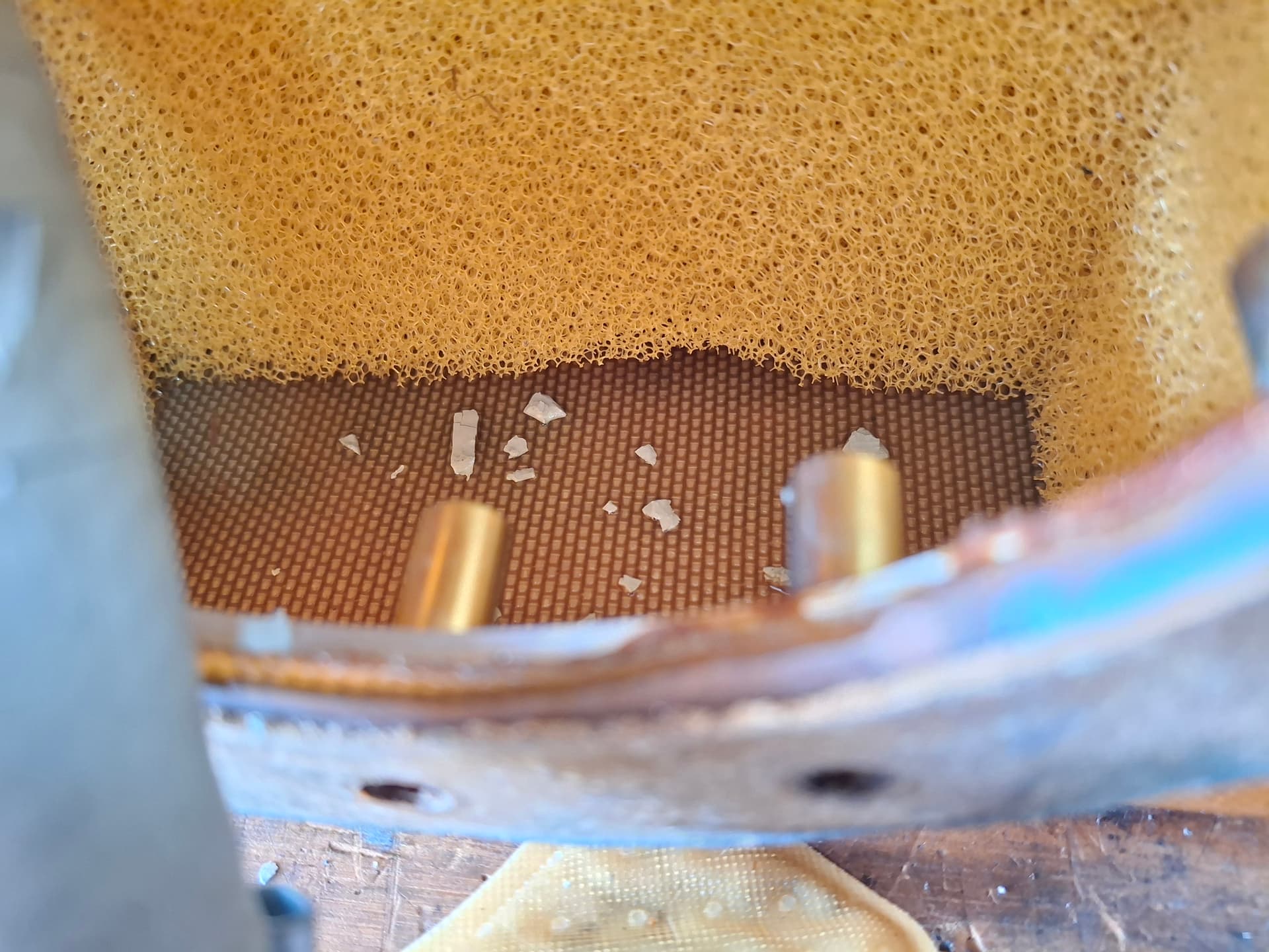
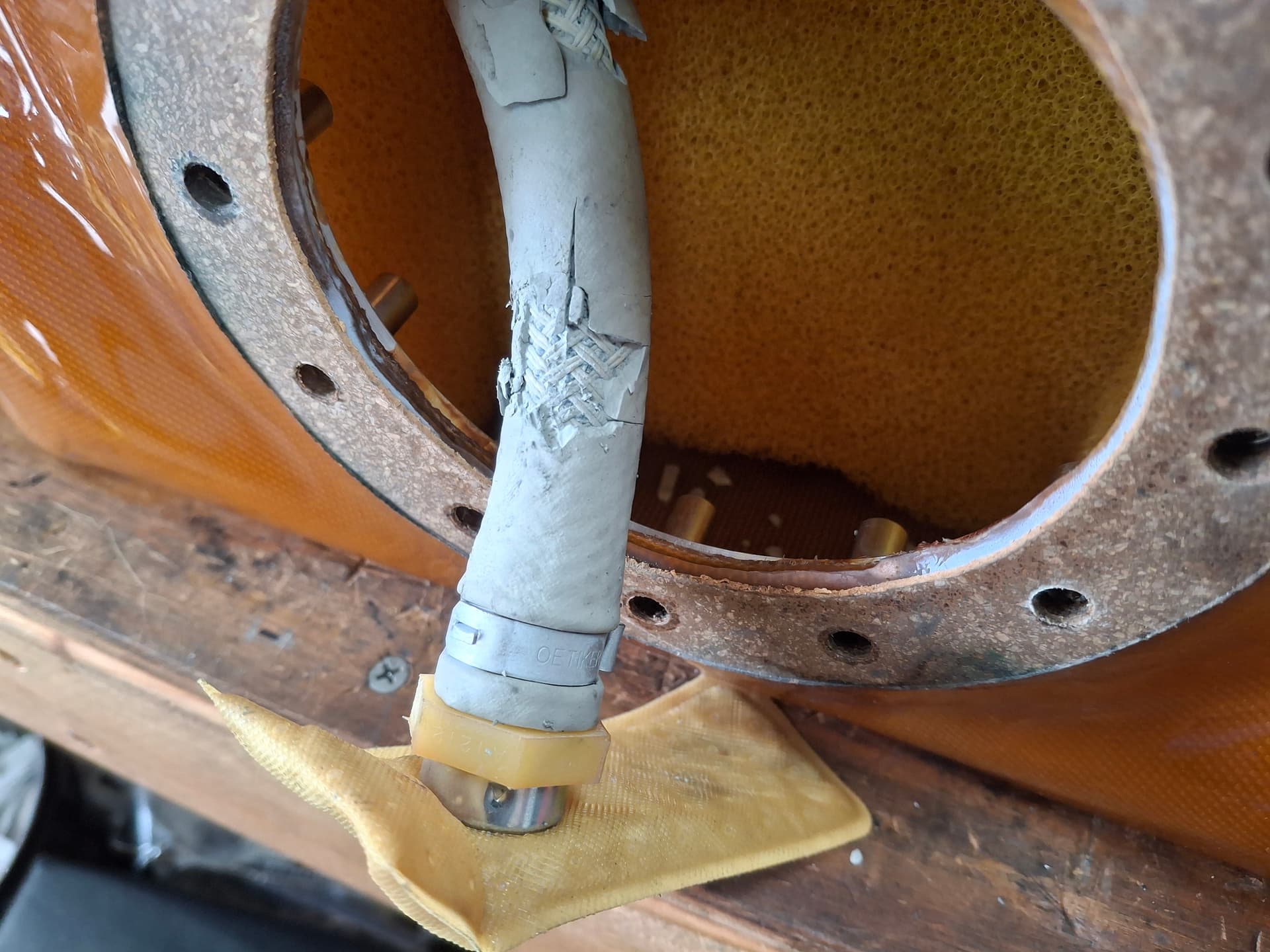
I degreased and scrubbed the exterior of the bladder before removing the rear access panel to check the anti-slosh foam and for debris in the bladder. What I found was problematic. The pickup system uses a -8 AN male-male bulkhead that goes through the top of the bladder. A -8 AN push-on 45° hose end connects to the bulkhead. From there, a piece of -8 AN hose is crimped to the hose end with a fabric-type filter scrimped onto the bottom of the hose. The issue is that Fuel-Safe for some perplexing reason uses non-submersible Aeroquip -8 AN blue push-on hose, which I confirmed in their catalogue for replacement pickup hose. This type of hose needs to be SAE 30R10 rated for submersible, but the Aeroquip hose is SAE 30R7 where only the inner lining is fuel resistant and the outer isn’t. Upon pulling the bladder access plate, I found the hose crumbling like chalk with large chunks in the bottom of the bladder and finer particles clogging the filter and throughout the 1/2 gallon of fuel left in the bladder. The anti-slosh foam is in great condition, so I’ll soak it in a warm Simple Green solution to clean and reuse it.

The issue with repairing the pickup hose is that 1/2" SAE 30R10 is rare, particularly in short lengths. I’ve found long rolls for hundreds of dollars but haven’t been able to find affordable shorter per-foot or 3-foot lengths. 5/16" and 3/8" are readily available, but not 1/2". To address the pickup, I see no reason to maintain the hose system. I’m going to use a -8 AN flare nut or compression end to connect to the top bulkhead and run a piece of 1/2" aluminum tubing at an angle down to the center floor and turn that tubing horizontal for an inch or two off of the bladder floor. With this system, I get rid of the Mickey Mouse hose situation. Bending the aluminum tubing horizontal will protect the bladder from puncture in the event of a hard hit on the bottom. I’ll also ditch the tank filter since it’s just creating more work and wear for the pump and isn’t necessary to protect the mechanical diaphragm pump and since I’ll be running an in-line 40-micron filter between the pump and carb. One less thing to clog.

A lesson for others with Fuel-Safe fuel cells with hose pickups: I’d make it a habit during race-season prep to check the pickup hose. By using the Aeroquip non-submersible hose, Fuel-Safe has made this part a normal replacement part that will need changing however many years. Who knows how long it takes for the hose to degrade, but it will.

Post Alert:
@jonUU
@Sportsracer
@Datsun78
@Bob_Alder
@Rich
@Nick_H
@jackson_prime101
@Raybob9289
@GeorgeCurl
@dreimol
@berck
2 Likes

Firewall and Roll Bar Rehab
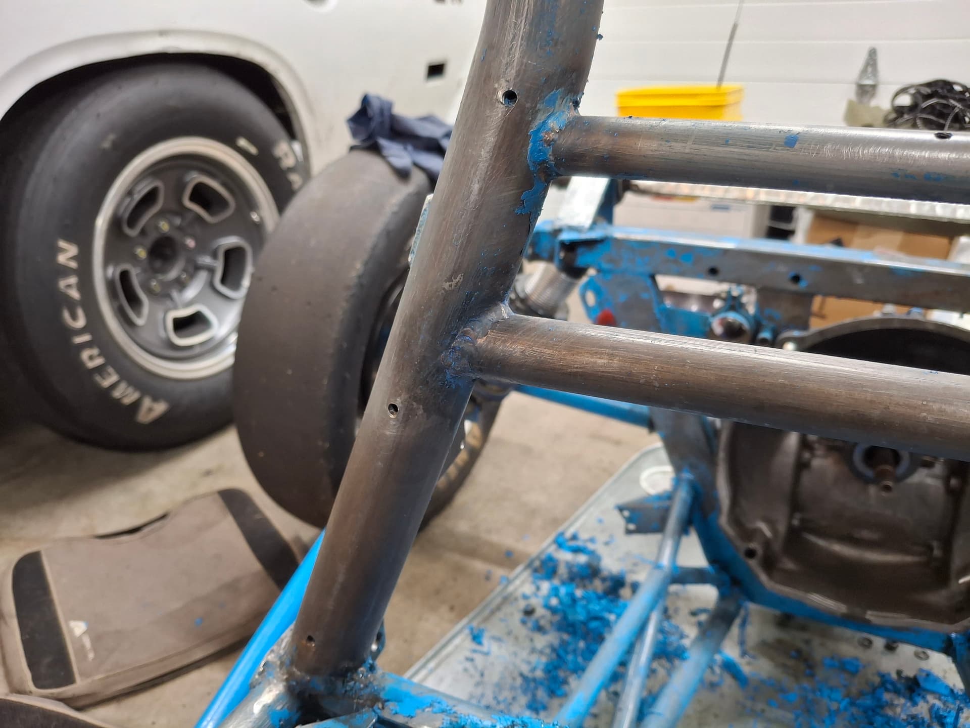
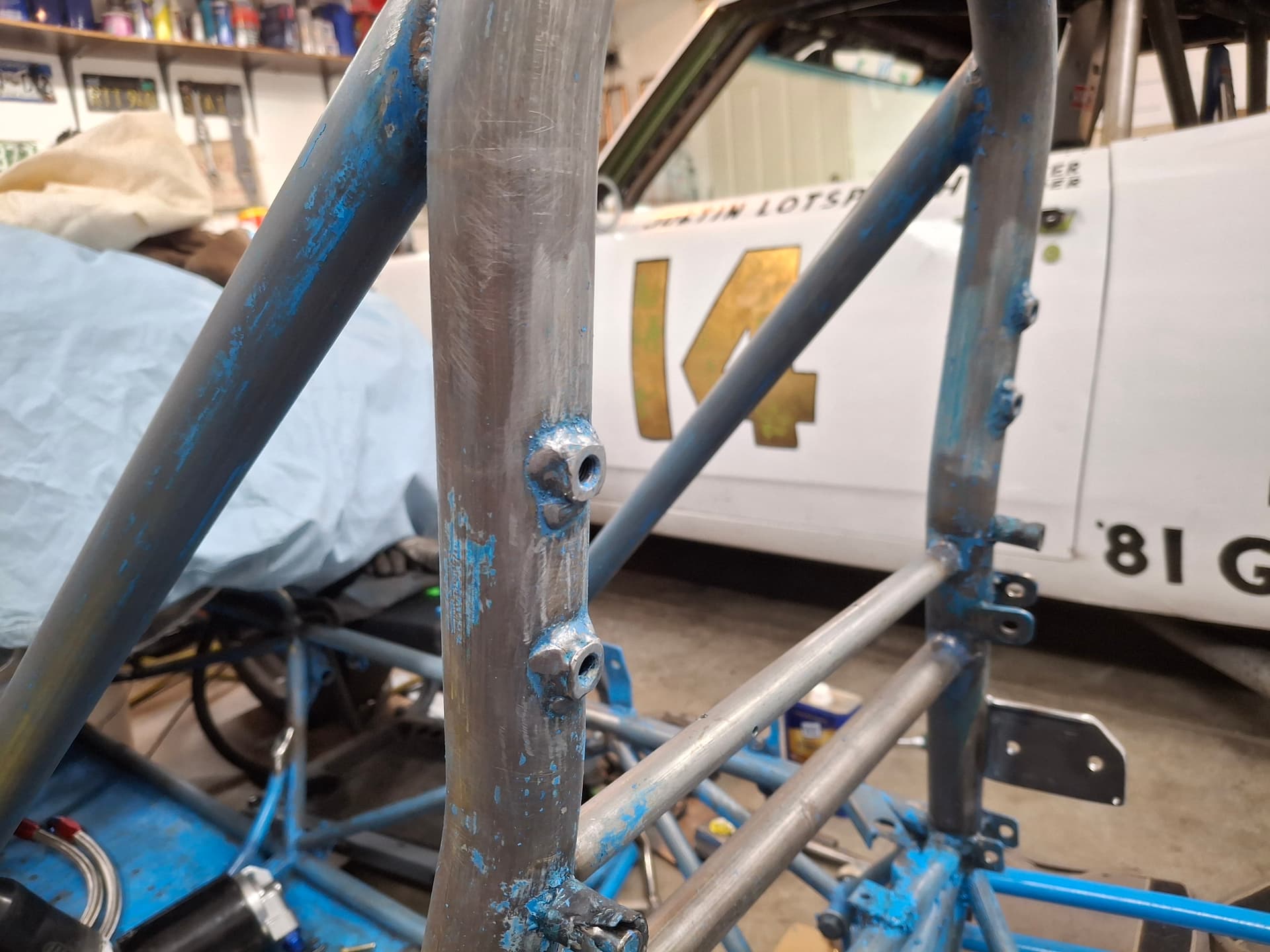
The firewall was two pieces of 0.040" 5052 aluminum with the bottom piece pop-riveted to the chassis and the top piece screwed into the roll bar. Someone other than Beach (they were MIG welded) also added four huge 1/2" diameter holes drilled through the back of the roll bar for 5/16" threaded lugs that served to mount a panel/headrest. While a look around the RMVR paddock at both Formula Fords and Formula Vees will result in many such configurations with drilled roll bars, the practice isn’t legal per SCCA and RMVR. The 1972 GCR and RMVR General Rules protect the roll bar from holes (other than a single 3/16" minimum inspection hole), and SCCA’s and most other sanctioning bodies’ longstanding practice is that no holes are permitted in the roll bar due to the stress risers they create. I know RMVR Tech doesn’t enforce this rule, and the Beach isn’t legal for SCCA if I wanted to where I don’t care what SCCA tech thinks, but I’m not down with holes in the roll bar when it’s my neck under it–personal preference here. Of course, once drilled, you can’t get the tubing back to new, but I’d prefer a welded-up hole rather than a hole.
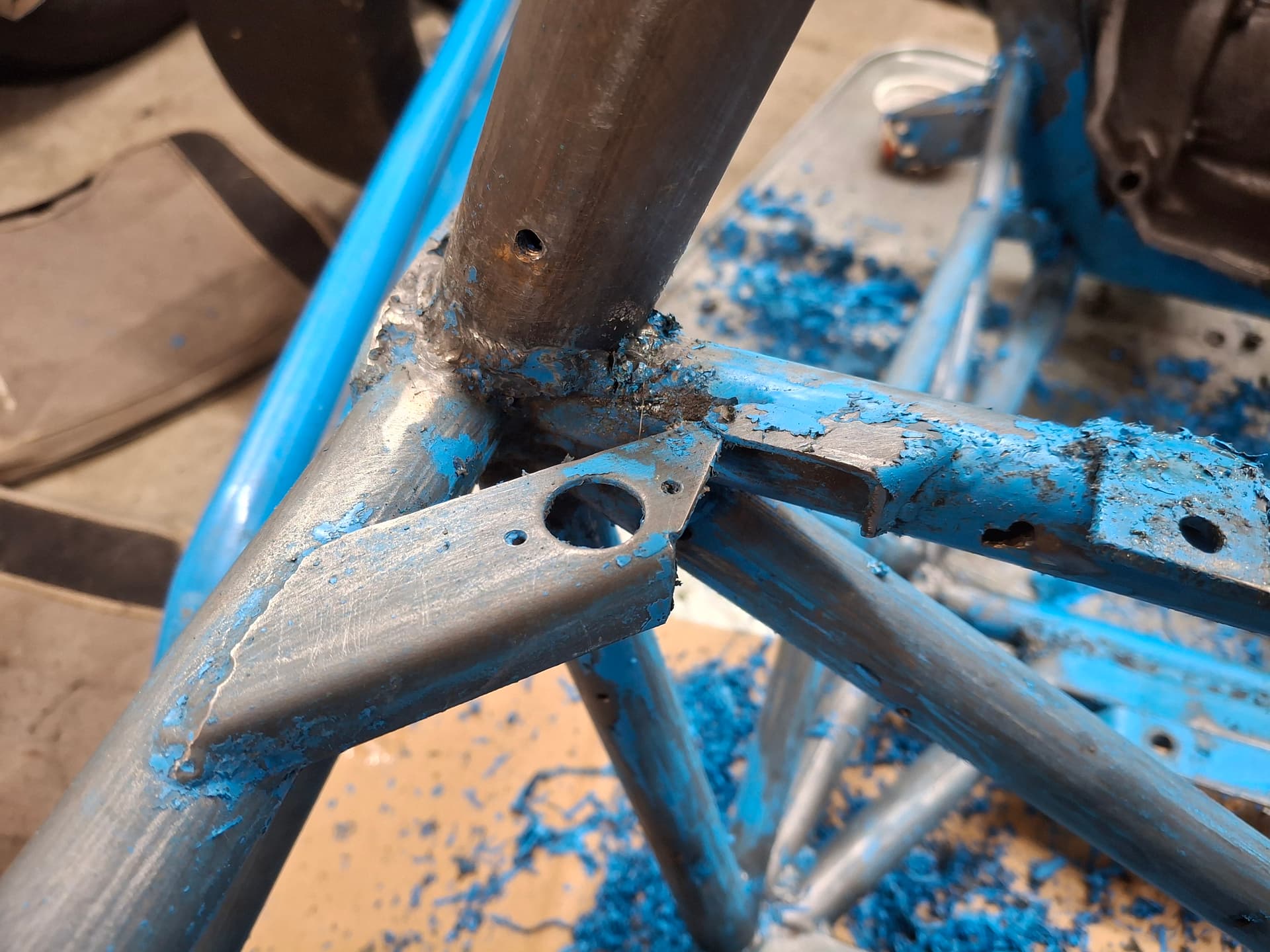
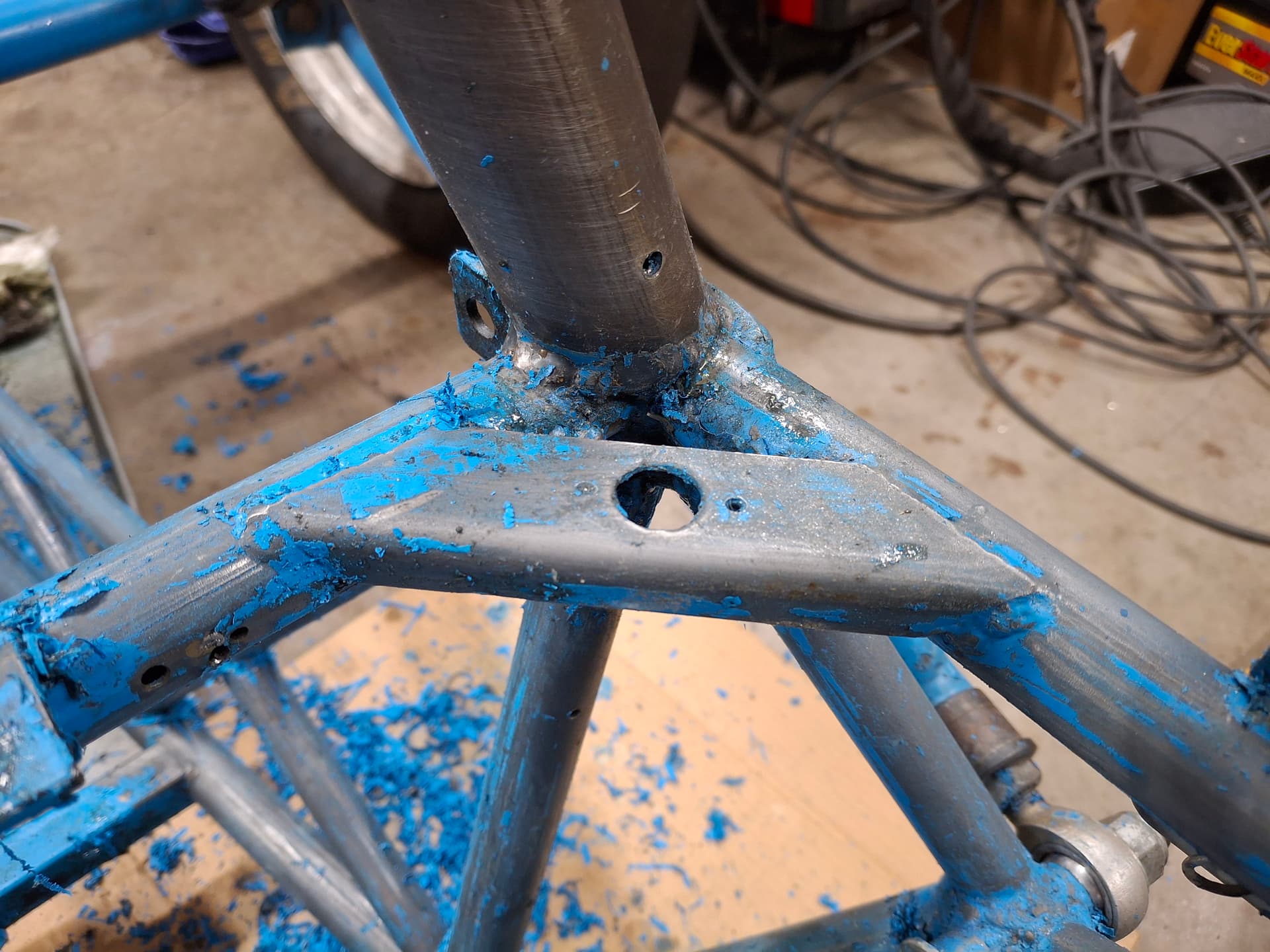
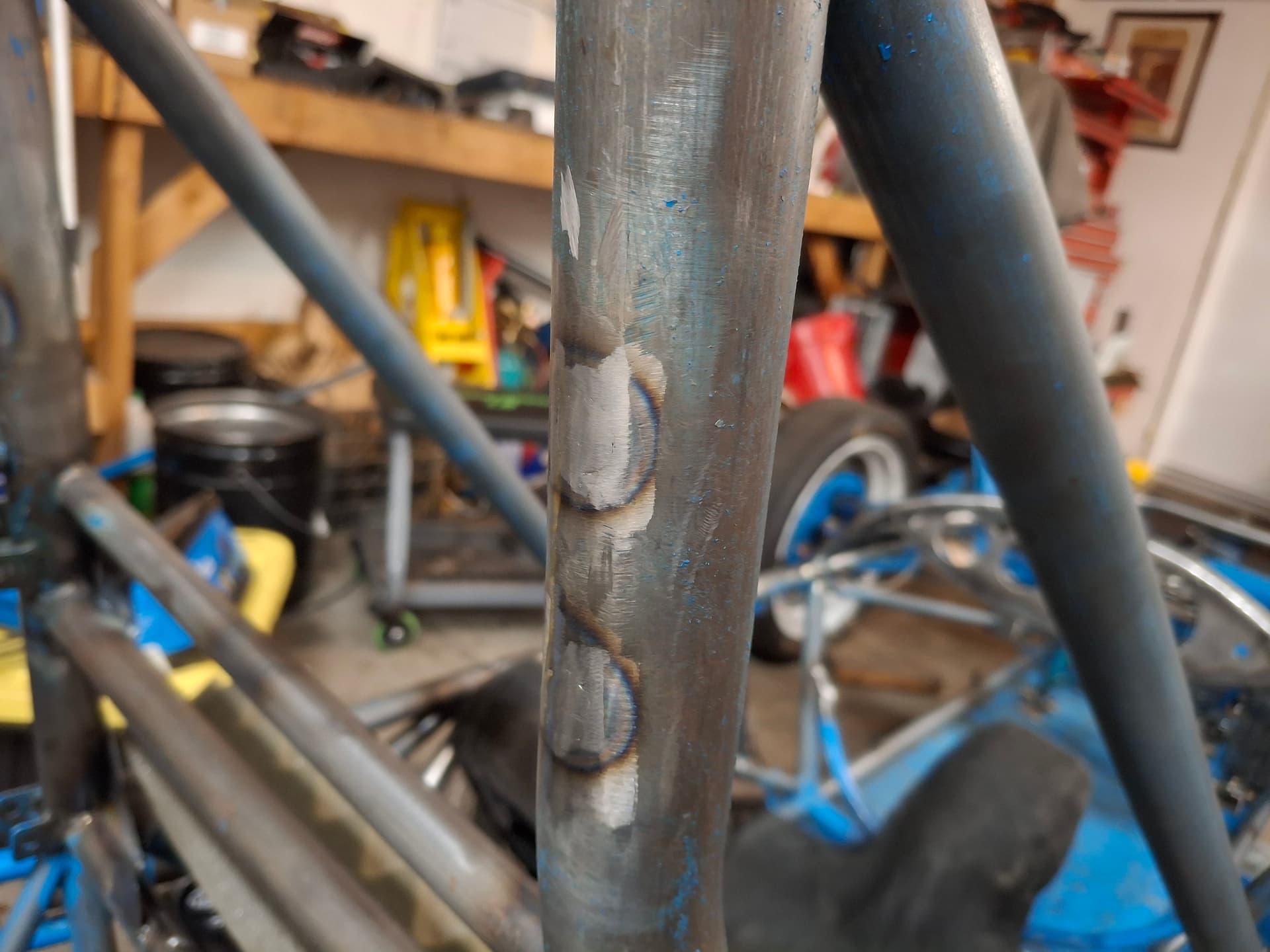
After stripping the paint, I cleaned out all the pop-rivets, prepped the metal, and welded up all the holes. In doing so, I also found a few older holes that had been brazed up at some point, so someone had the same idea in the past. After welding up the holes, I sanded and filed the welds being careful not to remove material from the surrounding tubing. I also removed a right-side gusset that had been hacked up and the same on the left with the intent of replacing them.

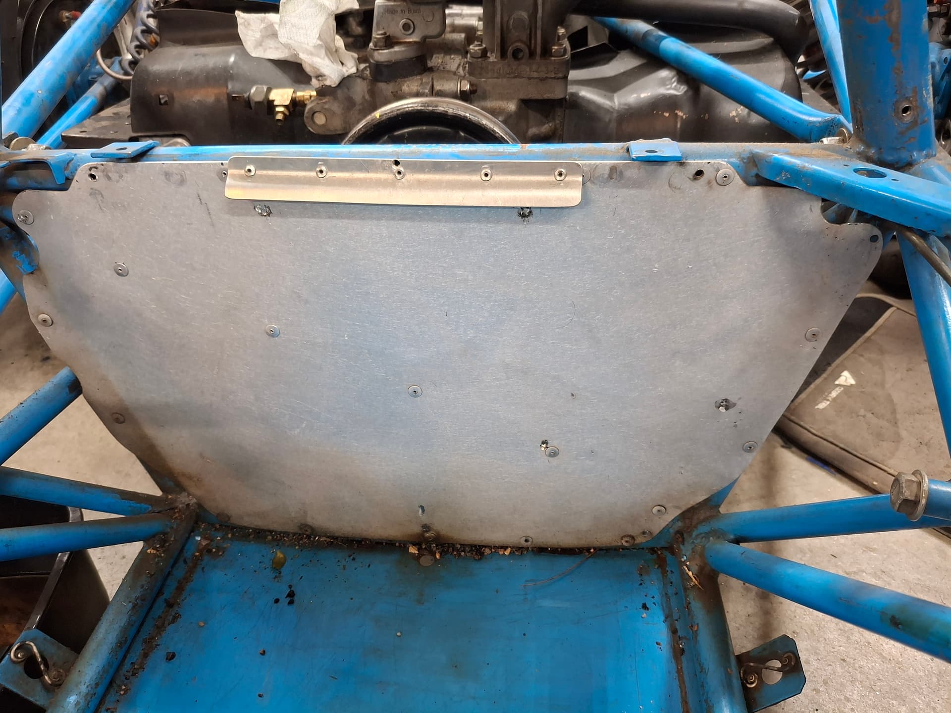
I fabricated a series of gussets that double as structural support for the roll bar system and mounting points for the new firewall and headrest. I also welded on mounting tabs for the top of the fuel cell housing and for the breather oil catch can. I cut out a template for the one-piece firewall, but I’m out of aluminum sheet and need to make a run up to Alreco Aluminum to get a sheet of 0.062" 5052 that I will use for the firewall and for new lower body panels when I get to that point in the project. The firewall will get some anti-vibration treatment (either flat weatherstrip or silicone dabs) and bolted to the gussets with 1/4" screws.

Post Alert:
@jonUU
@Sportsracer
@Datsun78
@Bob_Alder
@Rich
@Nick_H
@jackson_prime101
@Raybob9289
@GeorgeCurl
@dreimol
@berck