Justin, with all due respect, please don’t introduce a misunderstanding that trickles down into scrutineering (mal)practice. Your personal preference notwithstanding, drilled holes in the ROPS are not illegal under every set of rules with which I am familiar (including FIA Appendix K). If you know otherwise, please quote those regs explicitly. A rollbar through-mount is the only realistic way to comply with the FIA requirement for a headrest in my 1960 Huffaker BMC mk1 FJ, for example, which has been scrutinized and passed tech many times with many different sanctioning organizations, and no question has ever been raised. Rich
@Rich, it’s a worthwhile discussion. My comments are specific to SCCA and RMVR, and I’ll push back that I’m not talking about personal preference but about a clear RMVR rule and the engineering principles the GCR relies on for the roll bar design.
From a technical safety standpoint, safety equipment in the SCCA GCR and RMVR General Rules fall into the area of “if the modification isn’t stated, it’s not allowed.” SCCA’s engineers specified the roll bar tubing size and design of Appendix Z assuming a continuous length of unadulterated tubing to withstand multiple loads (lateral, fore-aft, vertical). It would be impossible for the engineer to specify the tubing size and roll-bar design with the understanding it could have an unknown quantity, size, and location of holes drilled through it.
Drilling holes into the tubing (other than the one 3/16" inspection hole) changes its physical properties outside of the SCCA spec and moves the roll bar into the Appendix Z.1.I realm for “Other Roll Bar Designs” where one must present “data verifying the installation is able to withstand three simultaneously applied loads: 1.5 G lateral, 5.5 G fore-and-aft, and 7.5 G vertical.” If one wants to drill holes in the roll bar, that’s cool so long as he proves with data (e.g. a structural engineer’s report) that the roll bar will withstand the same forces used to calculate the unadulterated tubing size and design. No holes, follow SCCA’s engineer’s spec. Want holes, the structural engineering is on the owner to provide.
The expectation of no holes in the Appendix Z specified roll bar makes its way into other sections of the GCR and is very clearly stated in RMVR’s rules to support my interpretation:
Appendix Z.B.2 states that “An inspection hole of at least 3/16 inch diameter must be drilled in a non-critical area of the roll bar hoop to facilitate verification of wall thickness.” The key phrases here are “an inspection hole” and “non-critical area.” The GCR goes out of its way to say one inspection hole and that it is not to be drilled in a critical area of the roll bar because the expectation is that no holes are drilled in the roll bar aside from this one inspection hole in a safe spot. If the SCCA didn’t care that holes are drilled in the roll bar wherever one wants, they would not prescribe the inspection hole location be non-critical. The quantity and location specification makes it clear that the SCCA is not okay with holes being drilled willy-nilly in the roll bar and views the tubing integrity as critical.
The 1972 GCR 1.5.1.x.A Technical and Safety Inspection for the Formula car master switches states that the switch “can be mounted on a bracket welded to the inside of the upright member [i.e. roll bar vertical tubing] . . .” The key word is “welded.” It does not say screwed/bolted/riveted. If SCCA permitted holes drilled in the roll bar to mount equipment, they wouldn’t have specified a weld.
RMVR’s General Rule D.17.c regarding Formula car master switches states that the switch “can be mounted on a bracket welded to the inside of the upright member. . . . Drilling of holes in the roll bar/cage tubing to attach the bracket or switch is prohibited and may disqualify the roll bar.” RMVR has historically followed SCCA, and it is clear from the RMVR rule that they have interpreted the GCR to prohibit holes drilled into the roll bar to mount equipment.
Out of curiosity, I searched through the 2026 SCCA GCR, and they apparently clarify some of these points further. The only areas I can find holes allowed in the roll cage including the 3/16" inspection hole, a bushed hole for a window net rod, and bushed holes for safety harness installation. The 2026 GCR, like the RMVR General Rule, specifically says that “drilling of holes in the roll cage to attach the [master switch] bracket is prohibited” (p. 28). If they specifically prohibit drilling holes in the roll cage to mount a switch bracket, it stands to reason that they would prohibit it for mounting other equipment. While I understand that we are focused on the 1972 GCR and RMVR General Rules, the 2026 GCR supports the older expectation of no holes in the roll bar.
The argument that more holes than the mandatory 3/16" inspection hole are allowed in the roll bar goes against the tubing and design specifications in the GCR and how both the GCR and RMVR make an effort to protect the roll bar from holes. Otherwise, what is the maximum size and quantity of holes I can drill in comparison to the tubing diameter and length? I’d be okay to drill twelve 1/8" pop-rivet holes for the firewall? How about six 5/16" holes for a headrest, oil catch tank, and ignition coil bracket? A 3/4" hole to run brake lines so I don’t have to job them around? How about 1/2" holes on 2" centers all the way around the roll bar hoop to lighten it so I can add that weight back under my seat? Where do we draw the line? The 1972 GCR and RMVR draws it for us with the expectation of no holes other than those listed are permitted because the rulebooks don’t list allowable modifications to the roll bar and instead either prohibit them outright, mandate welded brackets, or require engineering data to prove the design will withstand the same forces as an unmodified roll bar.
To your comment about FIA: I can’t speak to their historical practices and how they police things now with vintage cars, but I went ahead and reviewed a copy of the 1972 Appendix J out of curiosity (https://historicdb.fia.com/sites/default/files/regulations/1439540083/appendix_j_1972.pdf). It looks like SCCA and FIA share similar language regarding roll bars, but SCCA goes into far more detail. Most importantly, the SCCA and FIA use the same load calculations that I provide above and states that a different spec requires engineering data to prove it meets the FIA spec. I’m surprised they would instruct you to drill holes into the actual hoop versus doing whatever modifications are required to weld on a bracket, but because FIA instructed you to drill holes in the roll bar, your specific car homologates into RMVR. However, the 1972 SCCA GCR doesn’t allow drilling those holes, and the later GCR doesn’t allow it unless they double for the safety harness and are bushed.
That’s my take at least. As I said, RMVR doesn’t appear to any longer consistently enforce the no-holes in the roll bar, so it’s up to the driver to determine what level of safety is comfortable.
Steering Shaft Bushing Redesign
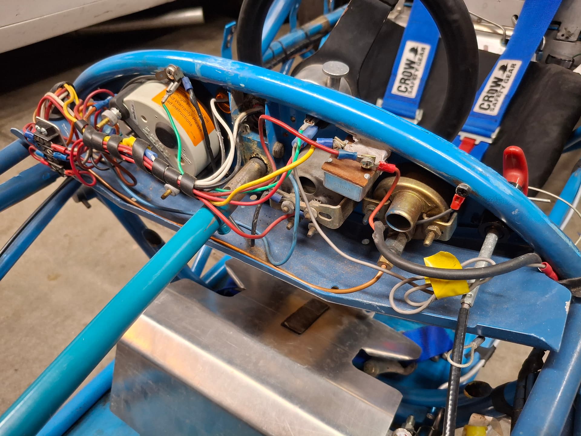
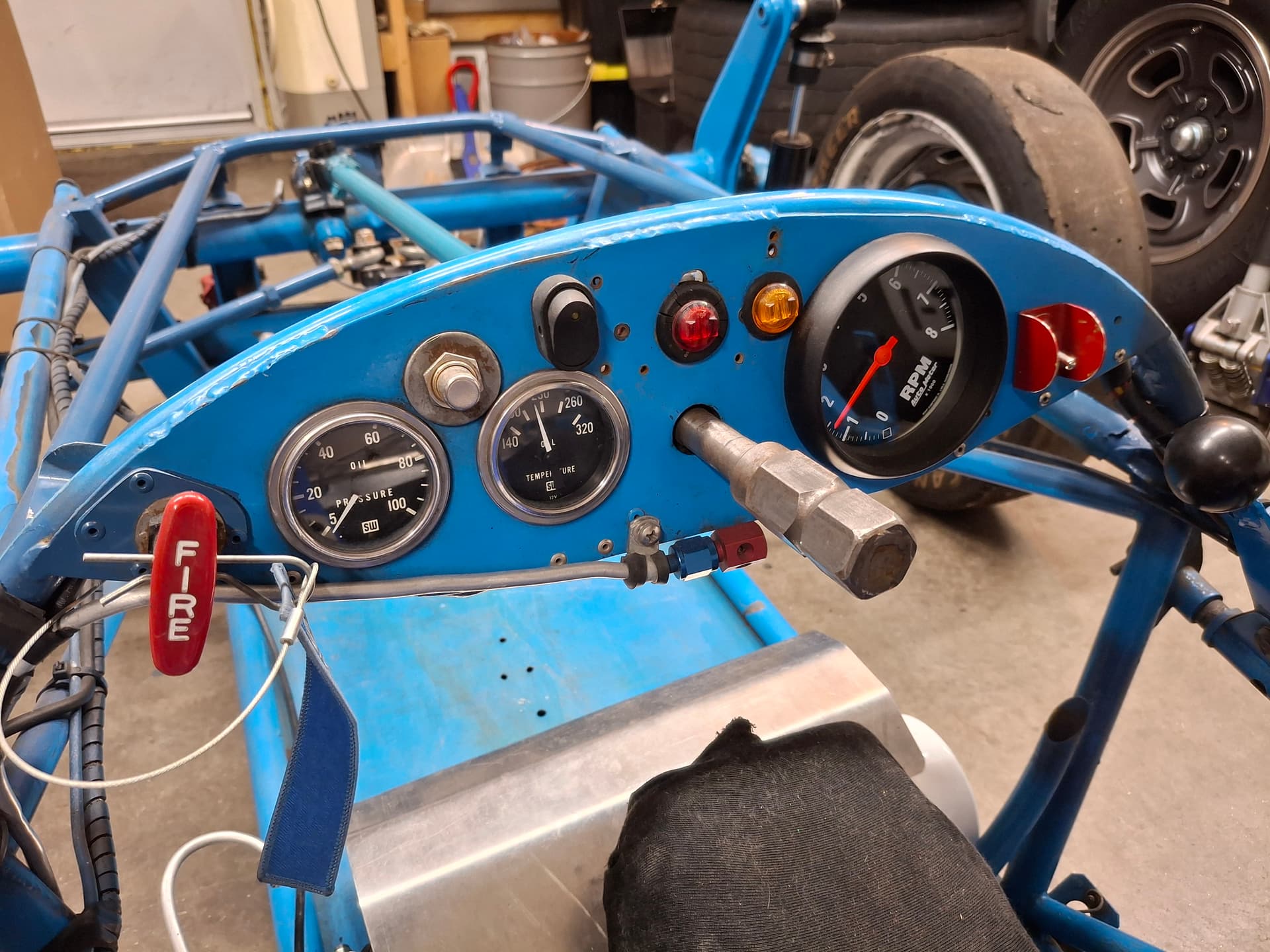
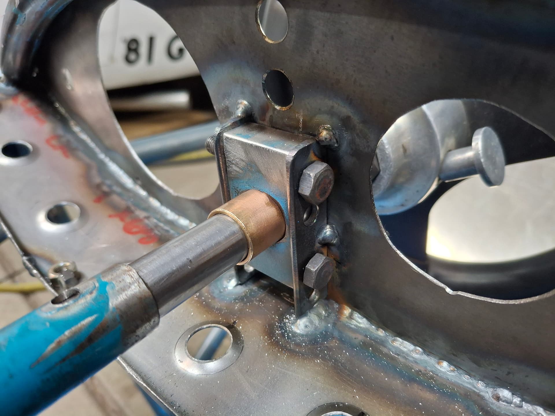
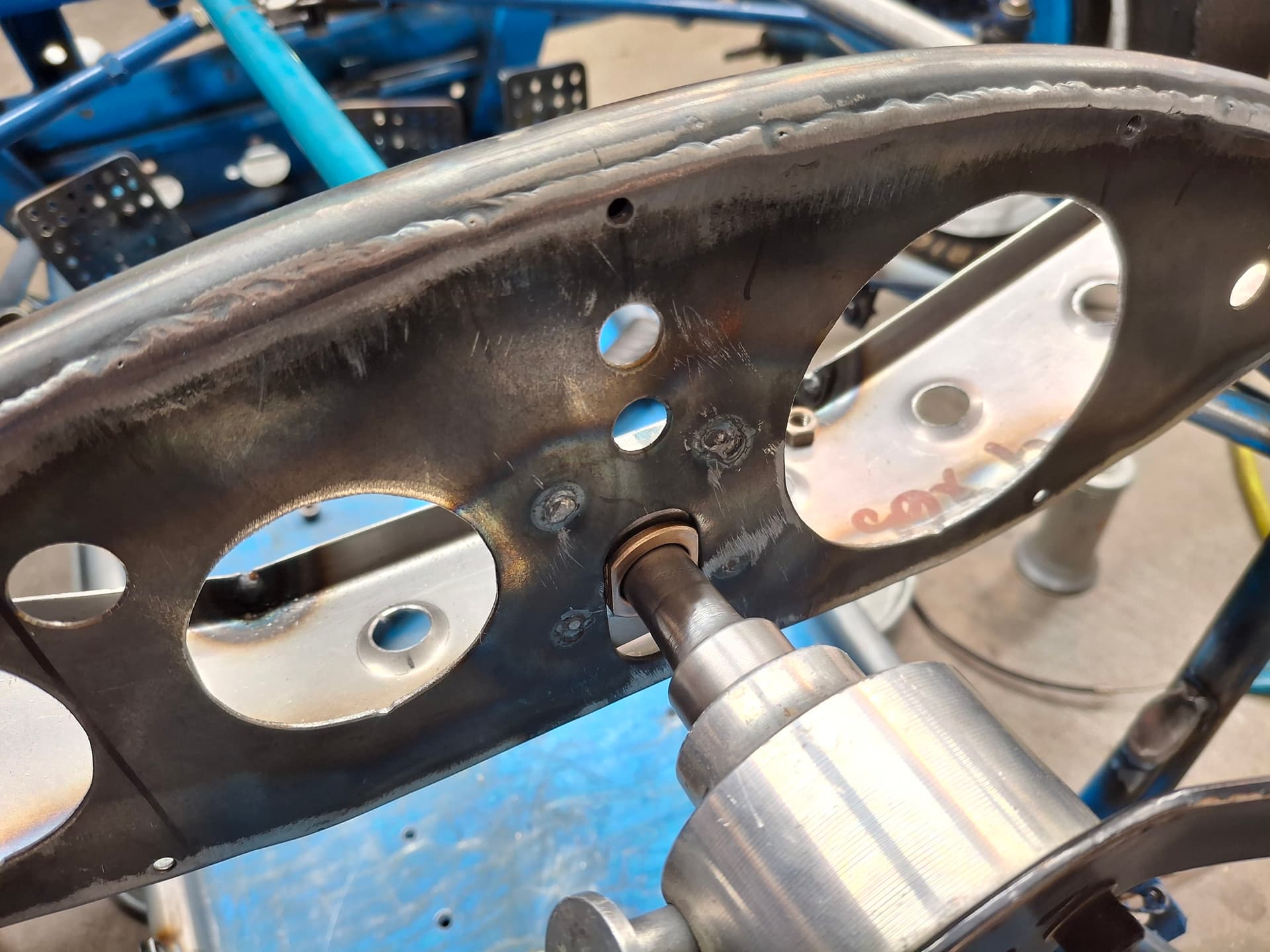
The 5/8" steering shaft ran through an aluminum block that was through-bolted to flanges riveted to the back of the dashboard. This configuration allowed for only one height position, and it created wear on the aluminum block. Over the years, the shaft had created about 1/16" of slop in the block to where the steering wheel clanked around.
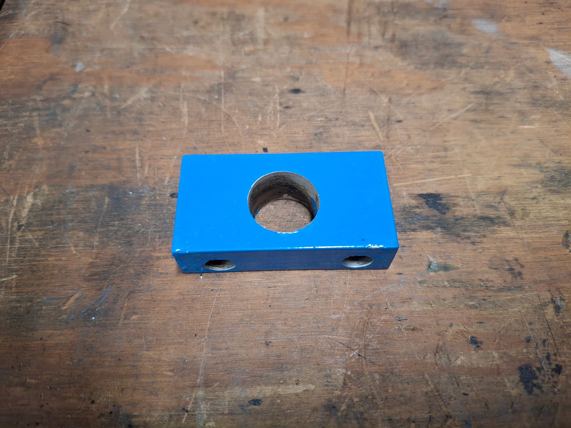
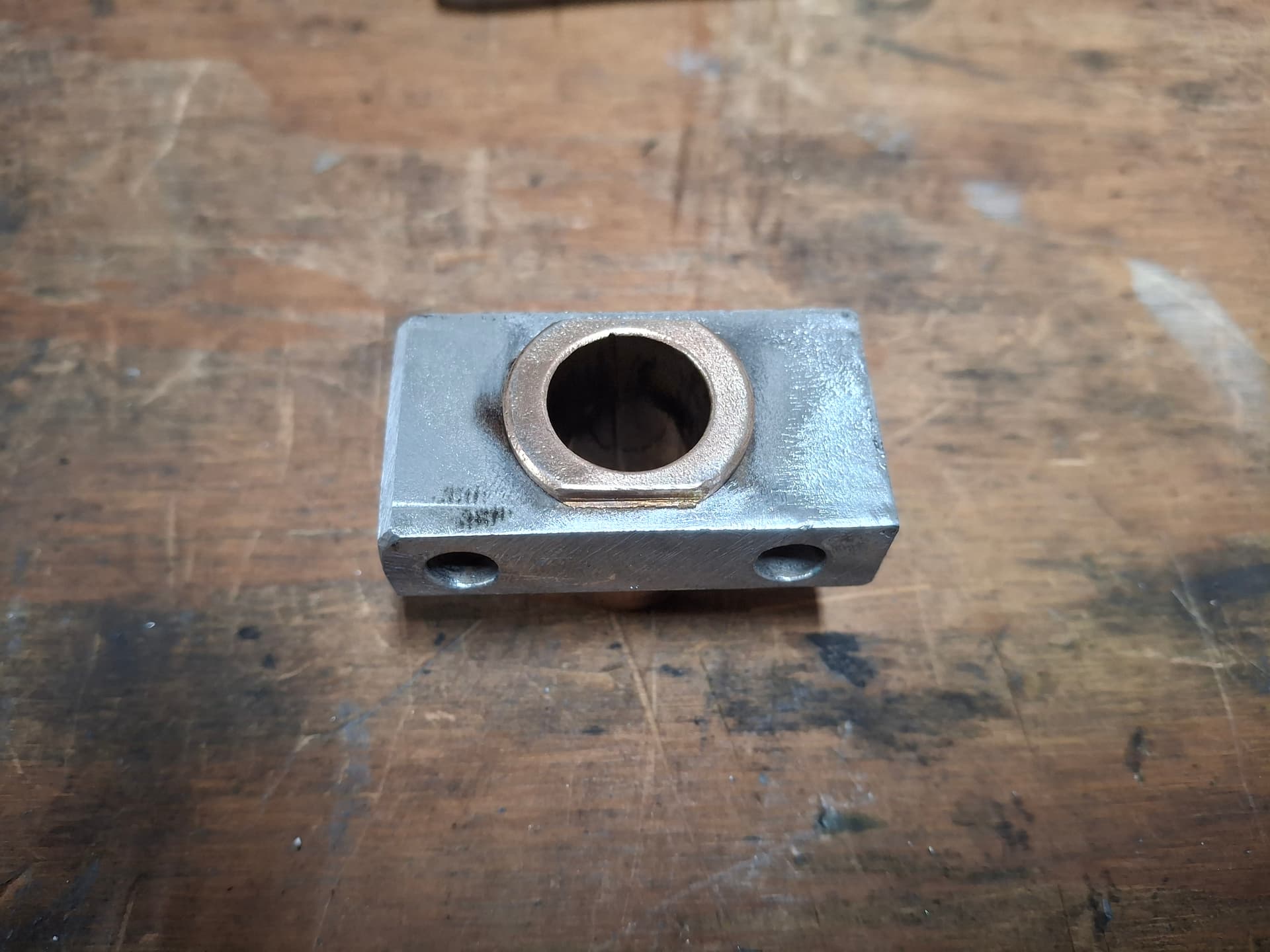
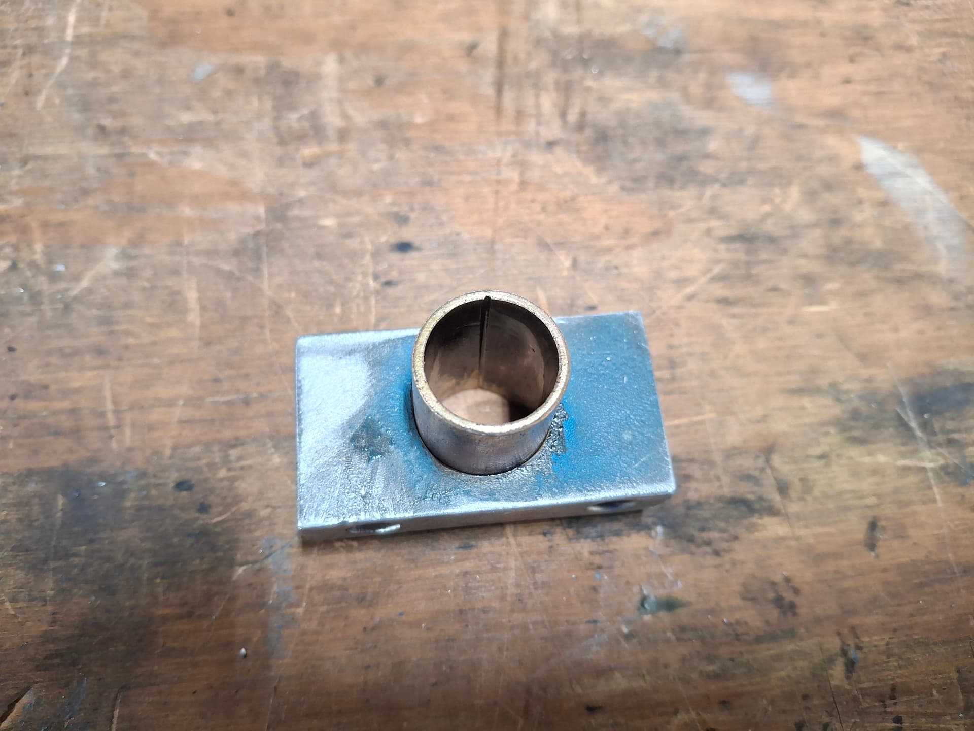
I drilled out the aluminum block to 11/16" and filed the hole until I got a tight press fit for a 3/4" OD x 5/8" ID Oilite bronze bushing. After pressing in the bushing, I file-reamed it for a tight fit against the steering shaft and cut a shallow oiling groove in the side for additional lubrication if needed. I filed the bushing’s face to index into the dashboard, and I fabricated flanges that allow for two height positions 1/2" apart. I need to get a couple socket-head alloy bolts to finish it off. Now as the bushing wears, which will take longer than the aluminum did being Oilite, it can be pressed out and a new one pressed in. You like my optimism that this car will be racing in 50 more years? 
Post Alert:
@jonUU
@Sportsracer
@Datsun78
@Bob_Alder
@Rich
@Nick_H
@jackson_prime101
@Raybob9289
@GeorgeCurl
@dreimol
@berck
You sure know how to stay busy!
A lathe would sure be a nice addition to your shop for fabrication needs. You might be able to find a bench top unit on line! I know your space is limited.
Hey Tom @Sportsracer, I would love a small mill and lathe. How easy life would be and cleaner my work would be. I actually have a working 18" 1950’s Craftsman benchtop lathe stored in the shed now buried in car parts. I just don’t have the workbench real estate for it since it requires more depth for the motor and gearing pulleys.
Before burying it again, consider a rolling lathe bench: put the motor and countershaft low and toward the wall, let the bed overhang the front, and add casters plus levelling feet. That gives you the extra depth only when you roll it out, and it can live against the wall otherwise. A fold-down or removable extension at the tailstock end can also help in a tight shop. Worth checking whether the Craftsman’s motor can be repositioned without changing pulley alignment.
1 Like
Electric Master Disconnect Switch and Rain Light Switch Revamp
When I inherited the Beach, the master disconnect switch was placed on the outside right behind the roll bar and inside the engine cowling vent to where I couldn’t reach it when belted in even with the belts completely loose. I had to throw off the belts, pull myself up a bit, and twist around and up to get it. It also had a “creative” bracket with sharp edges, the sharp fiberglass edges of the cowling, and the key dangled by yellow construction string line hose-clamped to the chassis brace. The rain light switch was crammed between other items on the dashboard.
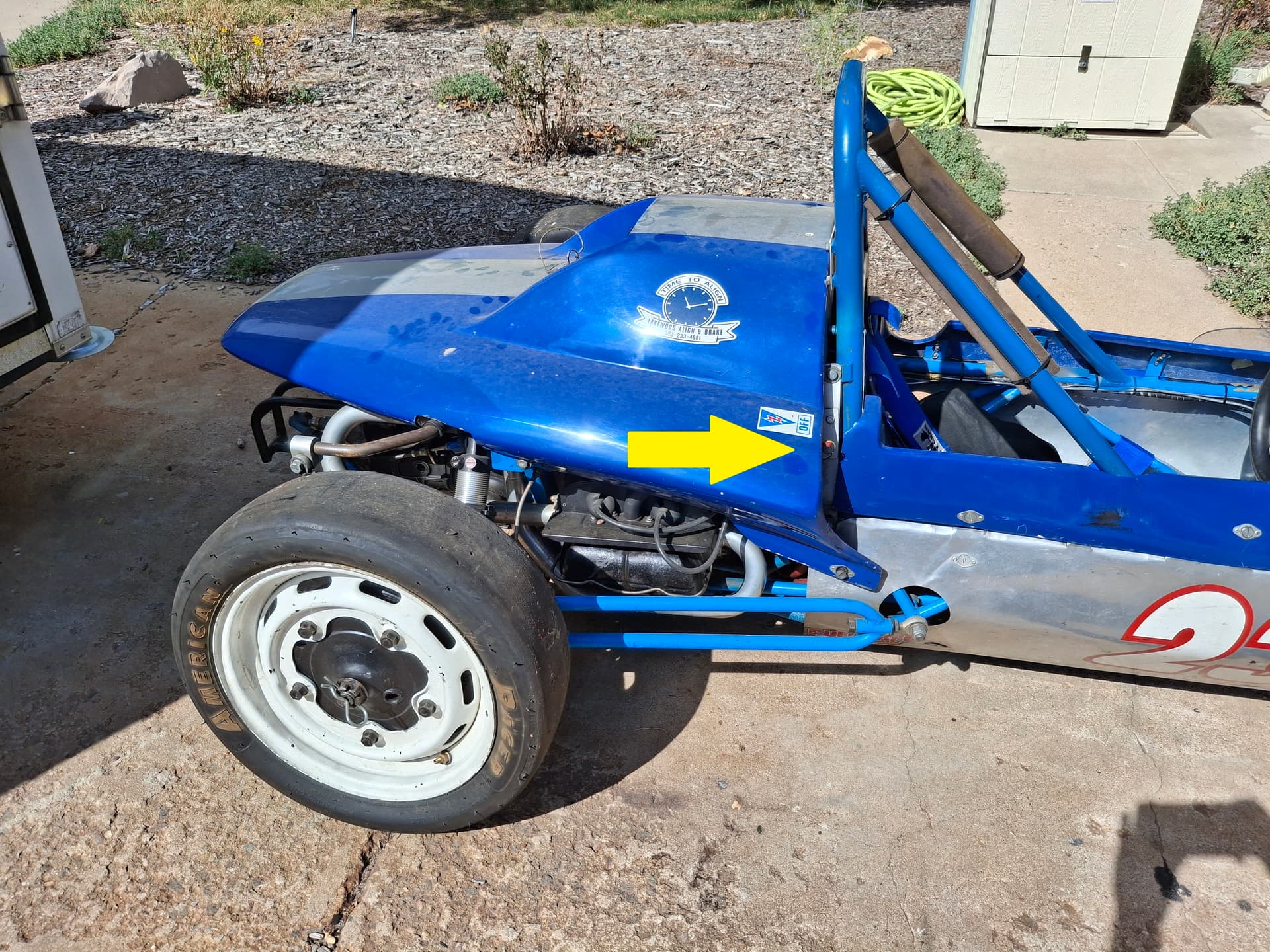
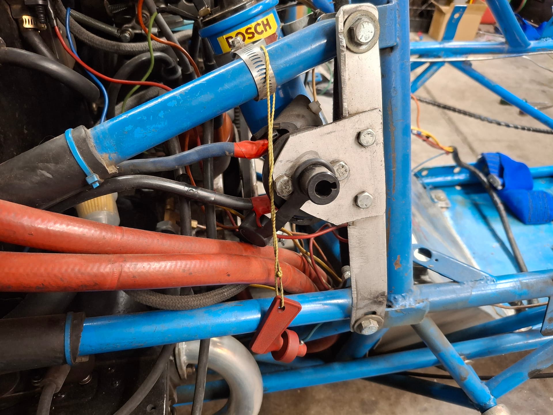
While I understand that the 1972 GCR places the standard master disconnect switch at the right roll-bar vertical and RMVR allows it there and many other places accessible by track workers, I could not find a location on the roll bar or firewall for the switch (clamping it all over the place while seated) that cleared my shoulders/head and that I could easily manipulate while belted in with helmet and HANS on, and I couldn’t find a place under the dashboard that didn’t hit my legs. I want easy, quick access to the switch when belted in.
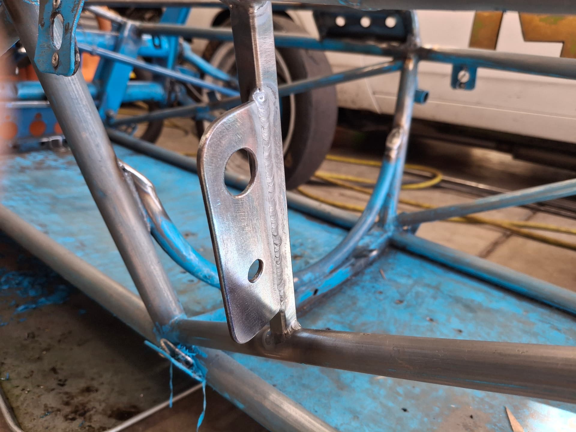
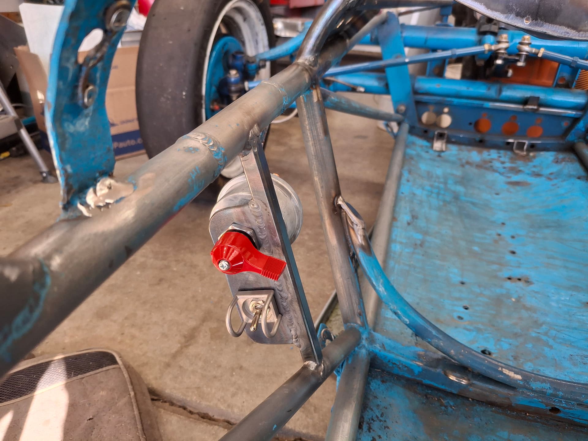
I played around with different configurations and found one that clears my body and is easy to reach from both inside the car and outside for track workers. There is also just enough room with the new lower aluminum body panels I’ll be fabricating for the switch body to clear. I welded a vertical brace and mounting plate across two chassis tubes on the left since there isn’t room on the right due to the shifter rod, and the left will reduce weight by requiring less copper cable than a right-side configuration since the battery and starter motor are on the left rear. I ran the mounting pate long enough on the bottom to accommodate one more toggle switch if one is ever required for equipment in the future. For the rain switch, I used the same guard that I will use on the dashboard ignition power toggle switch, which is an aluminum reproduction of late 1960’s US spacecraft guards for that vintage chef’s kiss.
Post Alert:
@jonUU
@Sportsracer
@Datsun78
@Bob_Alder
@Rich
@Nick_H
@jackson_prime101
@Raybob9289
@GeorgeCurl
@dreimol
@berck
Thanks Rob @robertrobinson. That’s not a bad idea at all, but I don’t even have the room to store the cart in the garage, and the shed has lawn between it and the garage side door. Maybe it’s time for me to build another shed and set up a little machine shop
Engine Cowling Mount Redesign
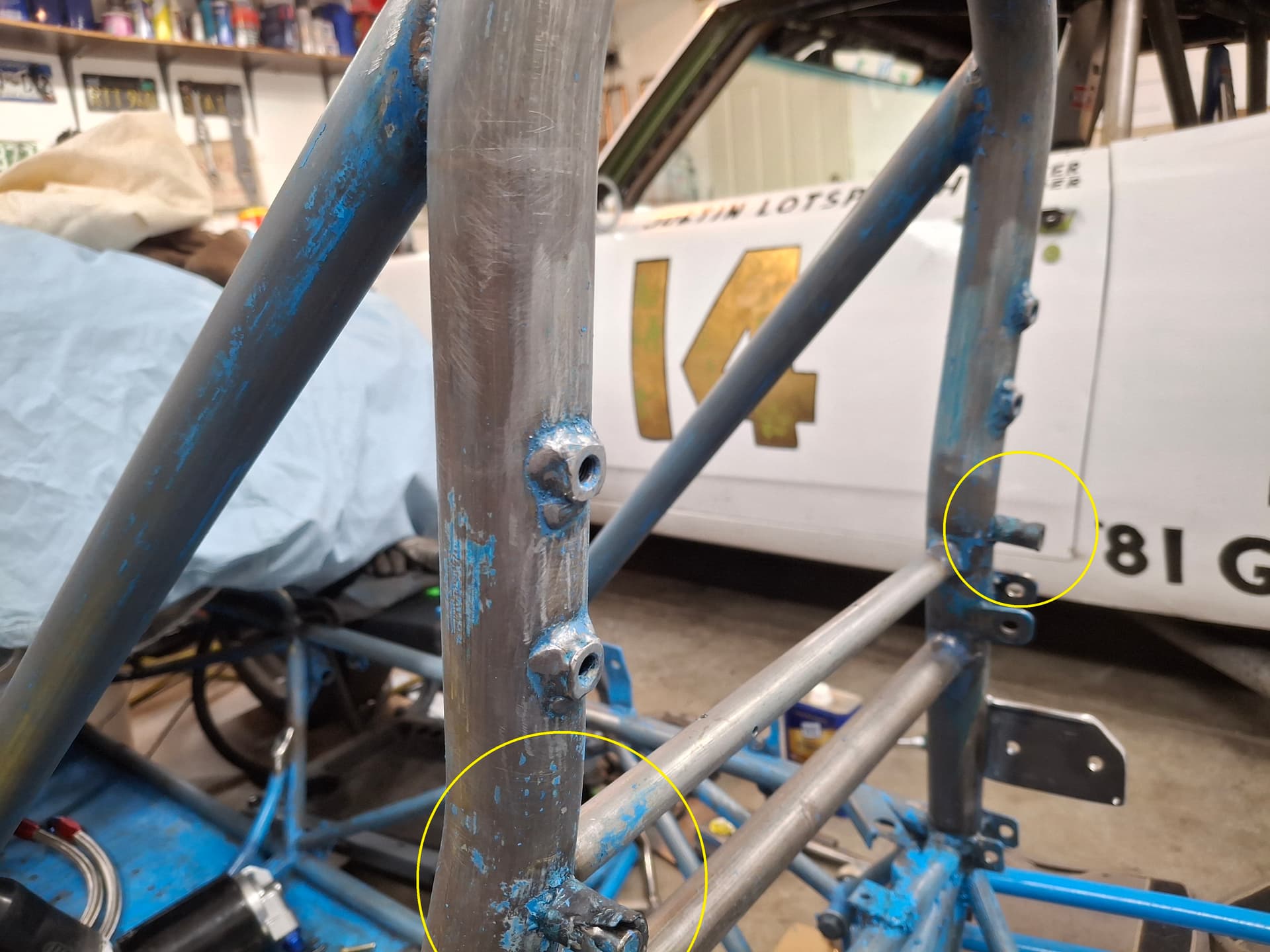
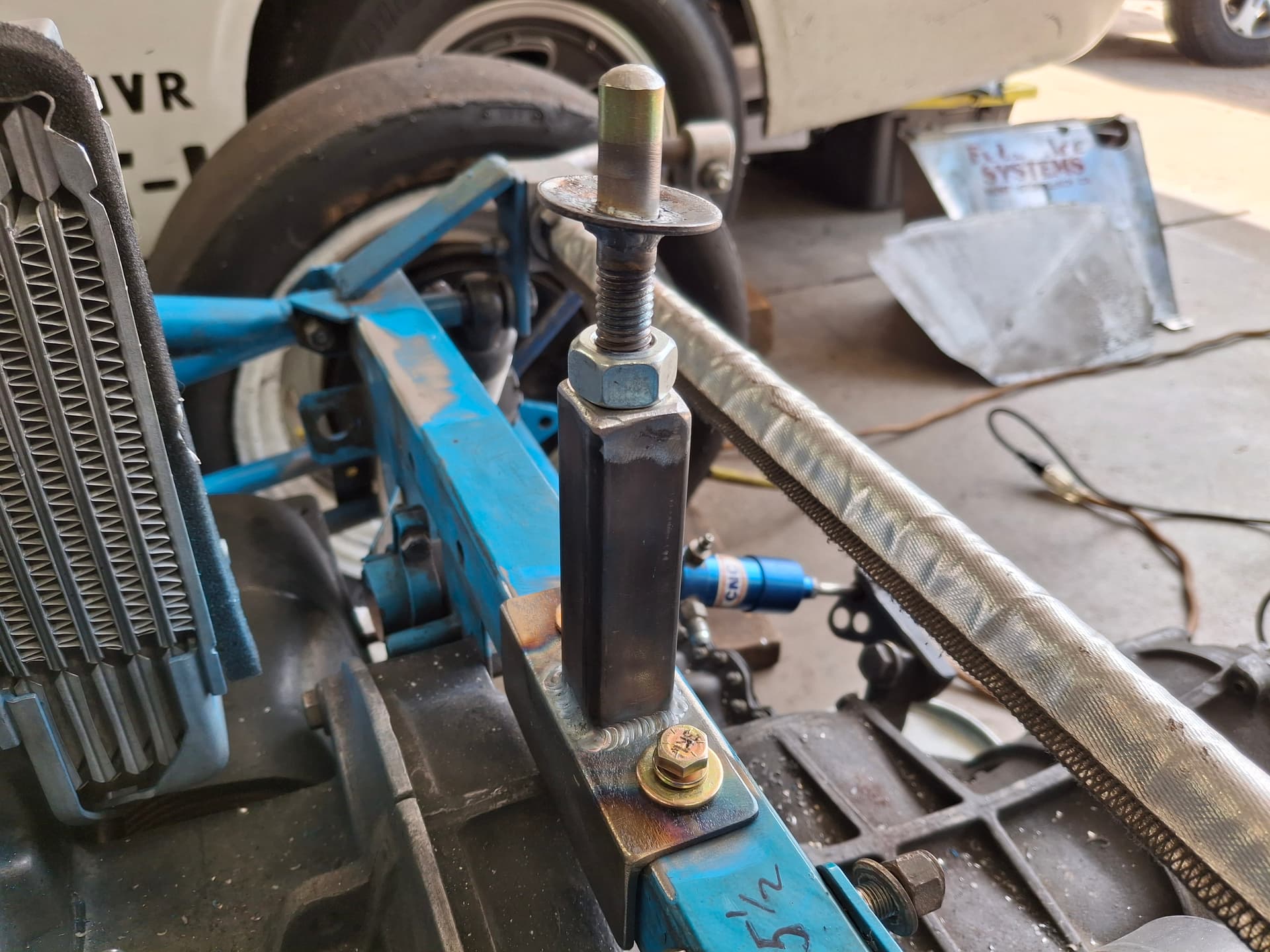
The engine cowling indexes on the roll bar verticals via two steel pegs wrapped in fuel hose (circled in the photo) and is located and locked down in the back by one center pin. I’m likely going to redesign the front pegs situation, possibly fabricating some type of polyurethane bushings into the fiberglass cowling since the current setup is hogging out the fiberglass holes even with the rubber fuel hose on the pegs. The rear mounting pin situation included an unnecessarily long horizontal aluminum strap, a flimsy vertical aluminum strap, and a flimsy angled bracket. Aside from adding clutter to the crossmember and unnecessary through-bolt holes on the vertical walls of the crossmember, the setup allowed the cowling to slide fore and aft by 1/2" with ease by hand, so I imagine it really buffered on track that likely exacerbated the fiberglass wear against the front pegs.
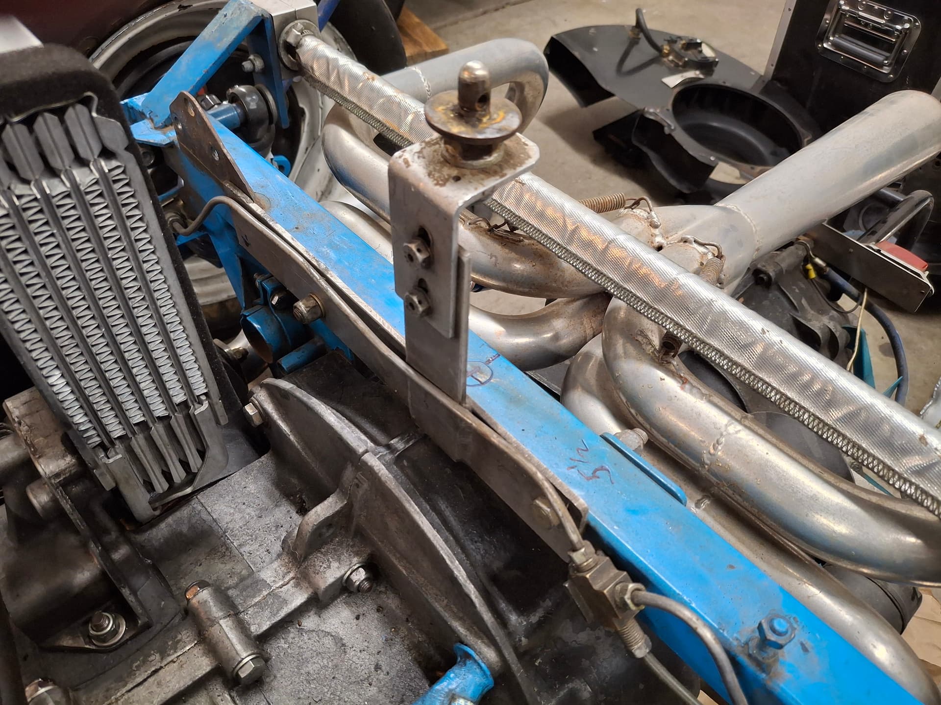
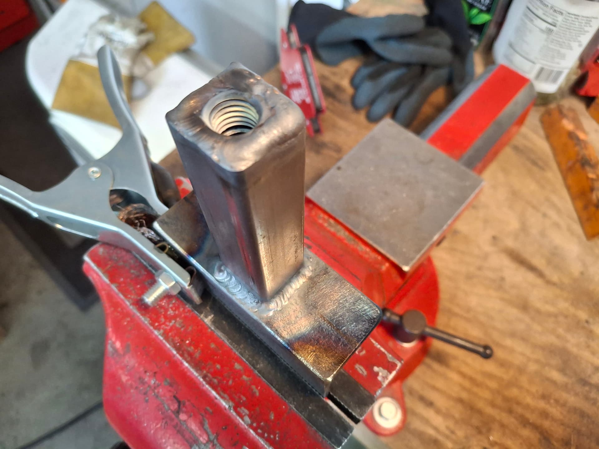
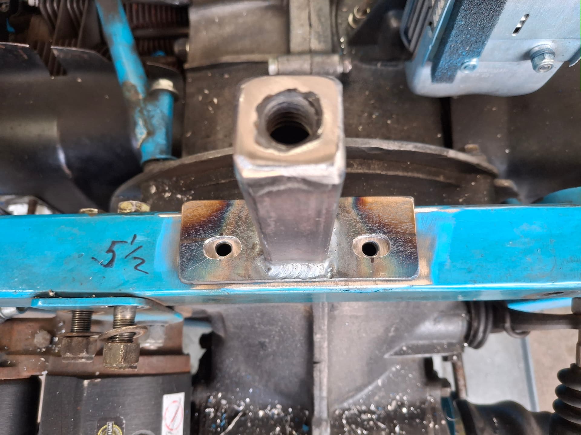
The solution was a new adjustable tower bracket and pin. The angled bottom bracket provides rigidity when bolted against the rear crossmember and locks the bracket from moving back, and the threaded bung allows for vertical adjustment. At the crossmember, I welded up and ground flat the unnecessary through-bolt holes, drilled two new holes in the top for the new mount, and welded in threaded bungs. I elongated the new bracket’s mounting holes to provide side-to-side adjustment for bodywork alignment. There is no real fore/aft adjustment since I located the tower where the cowling has a snug fit against the roll bar taking into account either the new bushings I’ll fabricate into the fiberglass or some form of rub block/bumper.
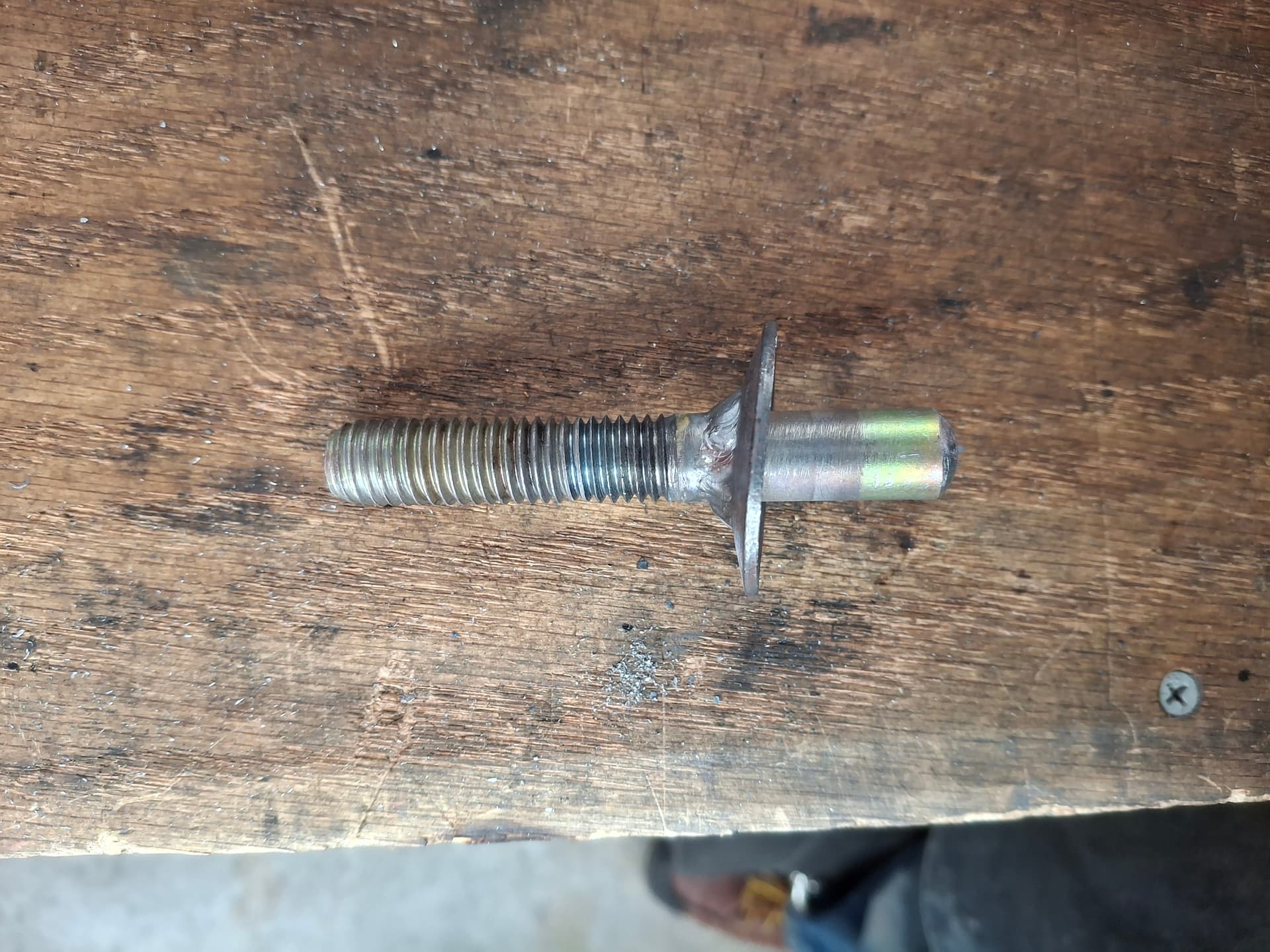
The old pin was hacked on, brazed up, and was too short at the top, which made locating the cowling a little more cumbersome by feel compared to if the pin were longer. I fabricated a new pin out of a 1/2" bolt, welded an old wide/thick shock-absorber washer on as a stop to spread the load on the cowling, cut off the bolt head, and rounded the end. If the pin develops surface rust where I rounded the end, it means I’m not racing frequently enough and acts as a warning for me to get my sh*t together . I’ll drill the hairpin hole after I have all the bodywork fitted and the mount adjusted.
The cowling is now good and secure, and the new setup weighs only 6 oz. more than the previous configuration. If I want to really get into moving as much weight down under my seat as possible, I may spend some time cutting the front vertical of the bracket shorter, drilling lightening holes in the bracket/tower, and sanding the jam nut thinner to shave off two or three ounces, but that’s a lot of work for a vintage club. Probably better off losing 3 ounces of body weight  Next thing you know, I’ll be drilling out bolts and chambering the bolt heads like we used to do on the champ and sprint cars.
Post Alert:
@jonUU
@Sportsracer
@Datsun78
@Bob_Alder
@Nick_H
@jackson_prime101
@Raybob9289
@GeorgeCurl
@dreimol
@berck