Project Cuda: Building a 1969 Plymouth Barracuda Big Bore Car

While I don’t know how many people will be interested with the new RMVR forum in its infancy, I’ve officially started my build and decided to share the progress with the club. I do all my own work from roll cage, to suspension, to engine and drivetrain, to body/paint, so this thread will have it all. My goal is to have the car ready for testing and tuning at HPR by summer 2026 and have it painted and finished by fall 2026.

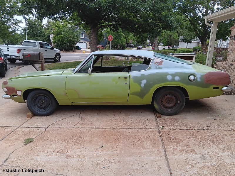
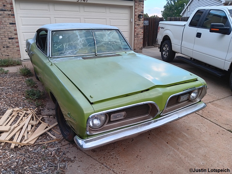
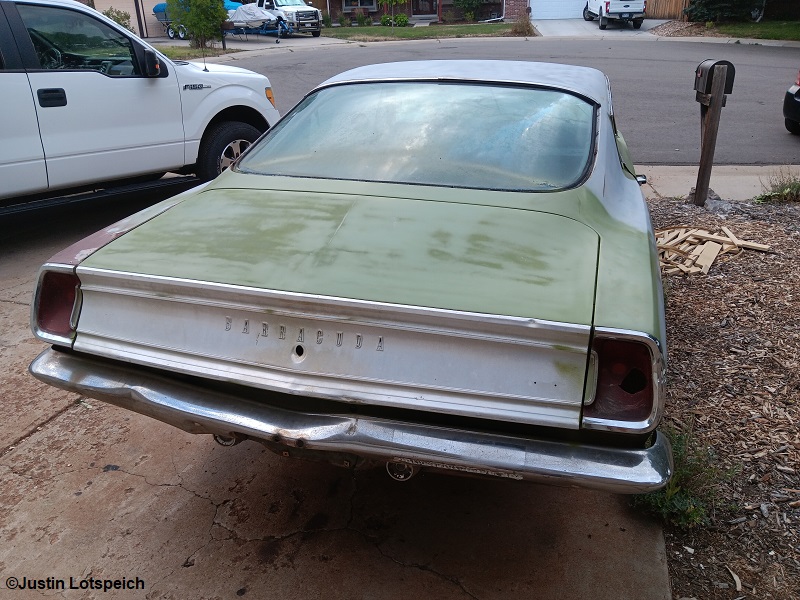
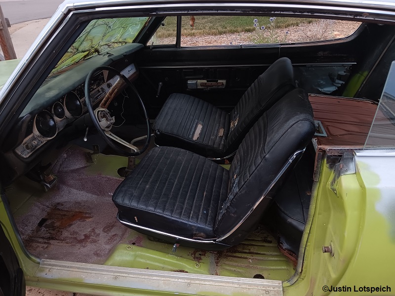
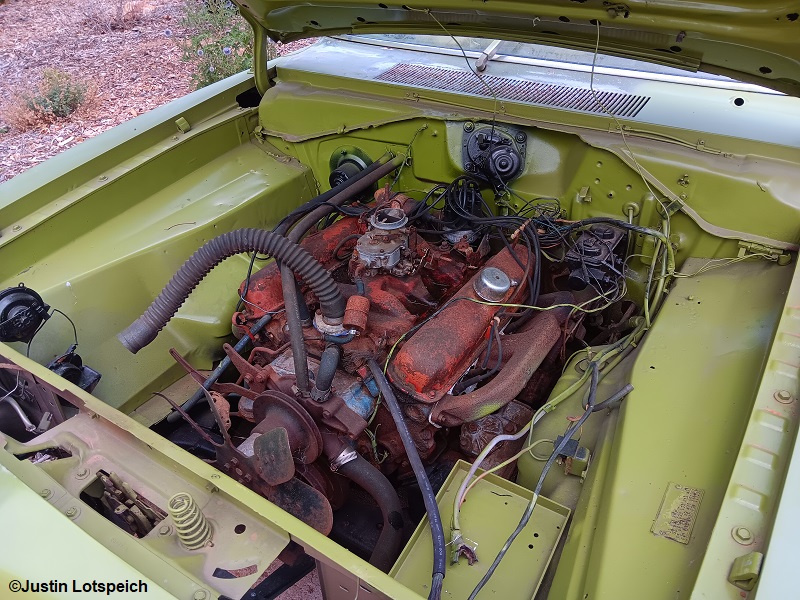
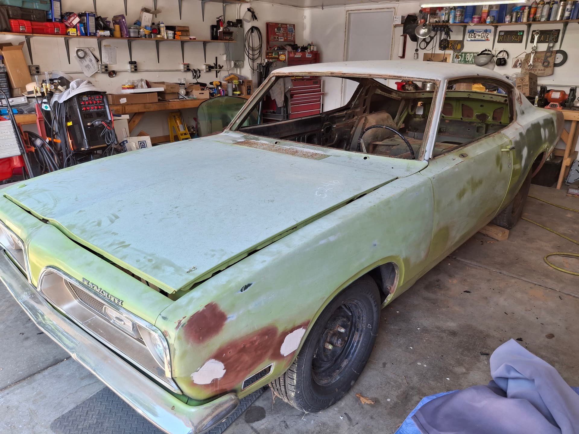
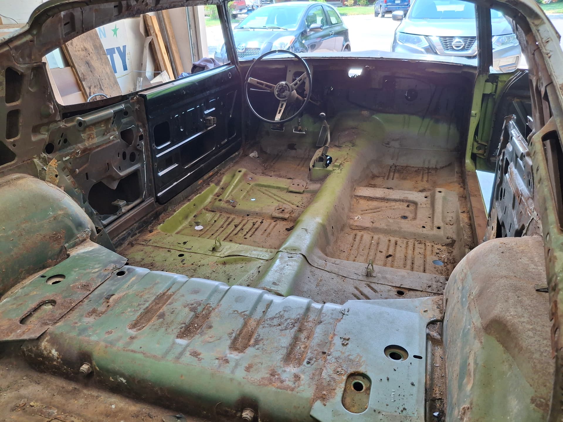
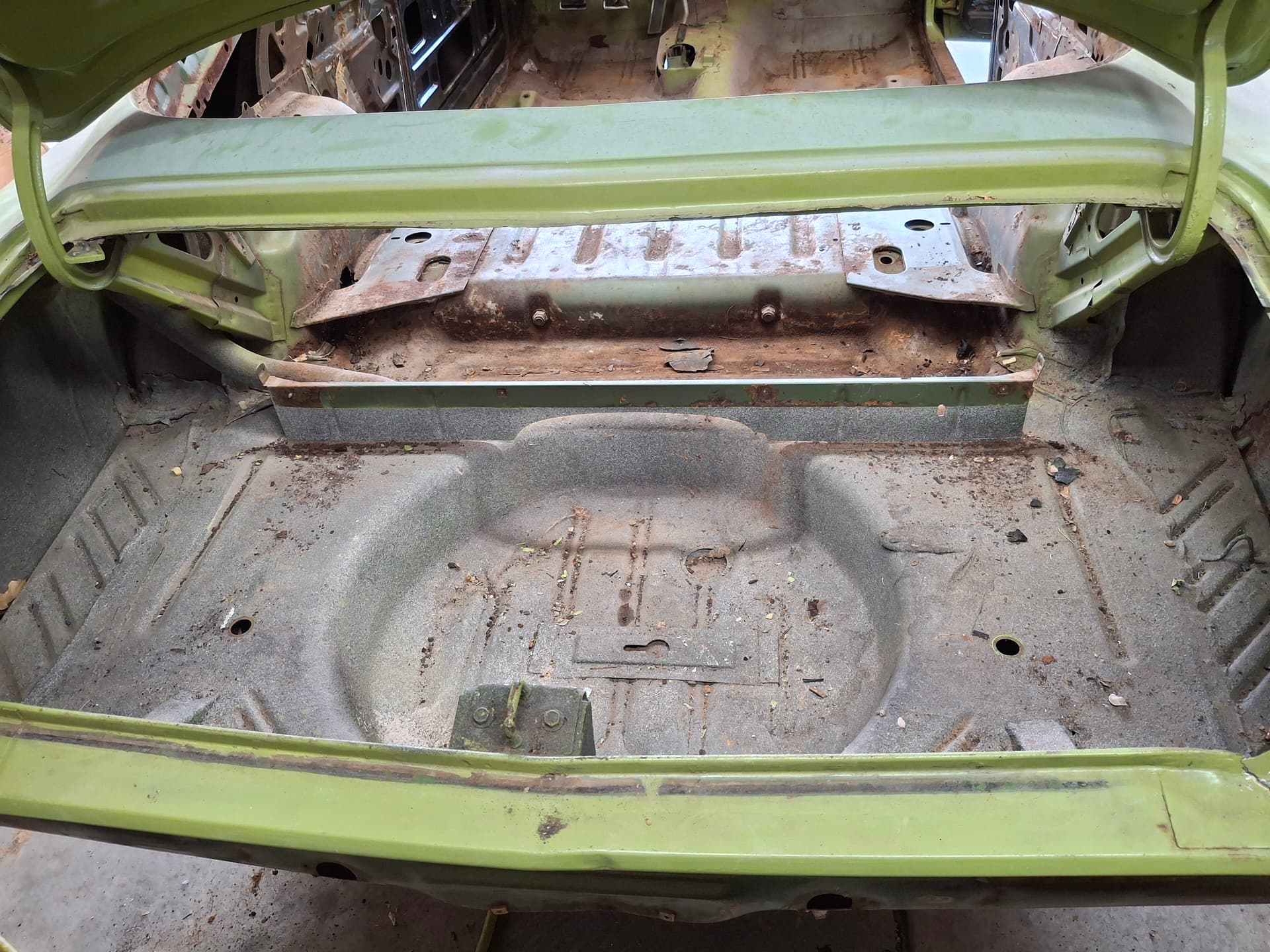
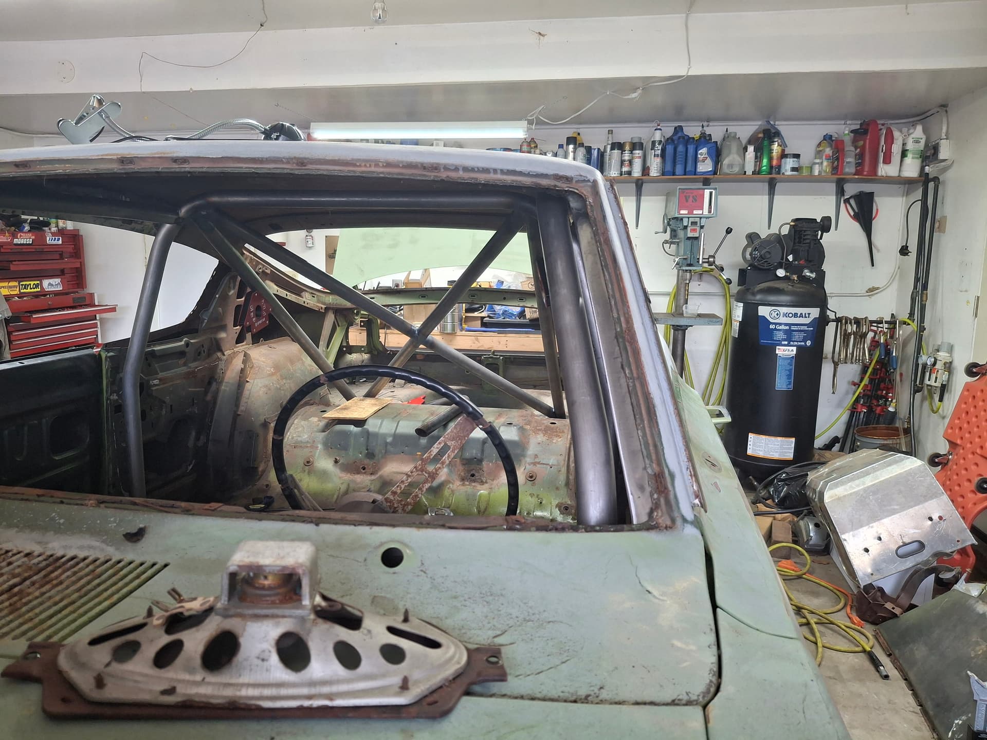
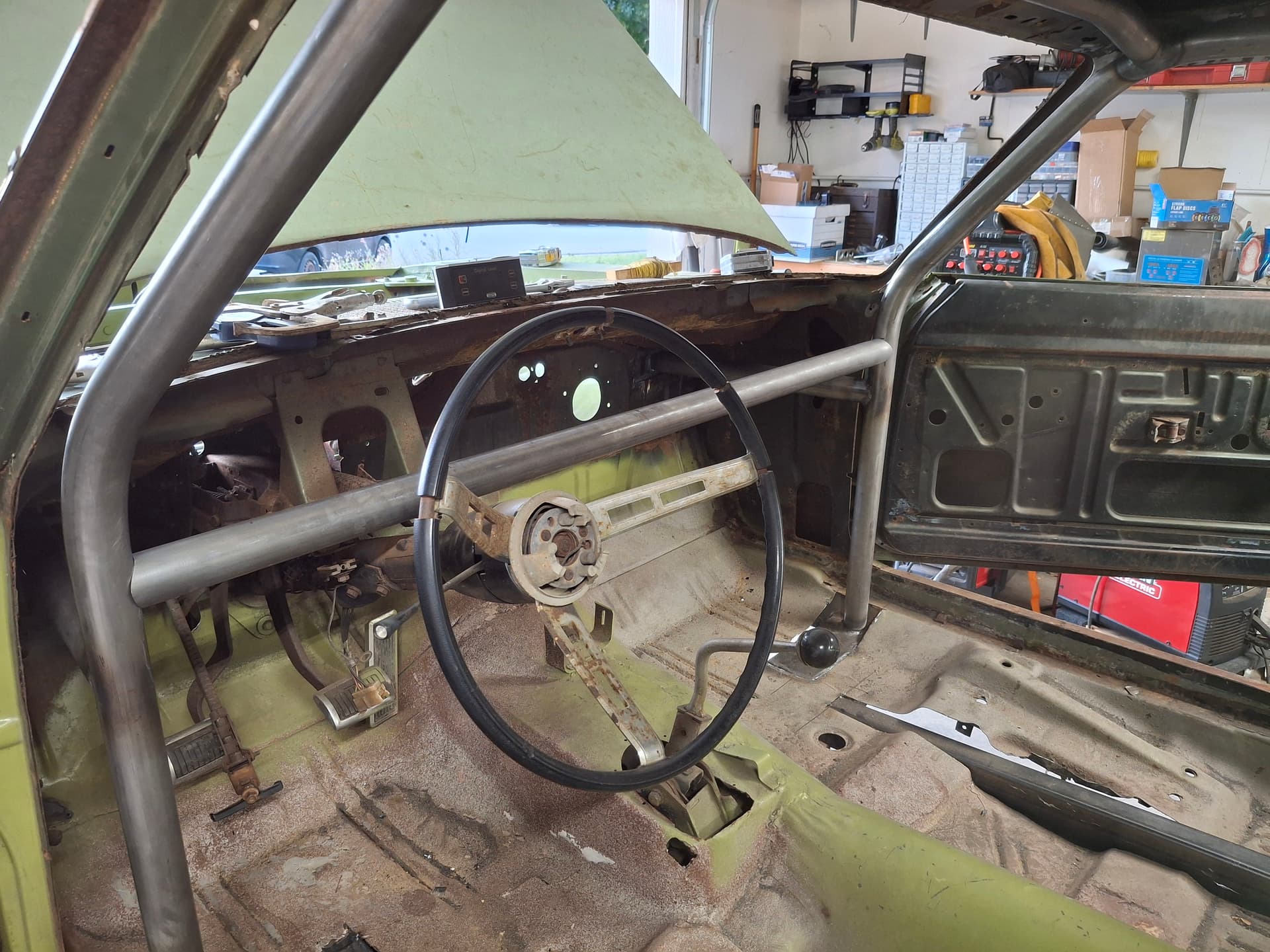
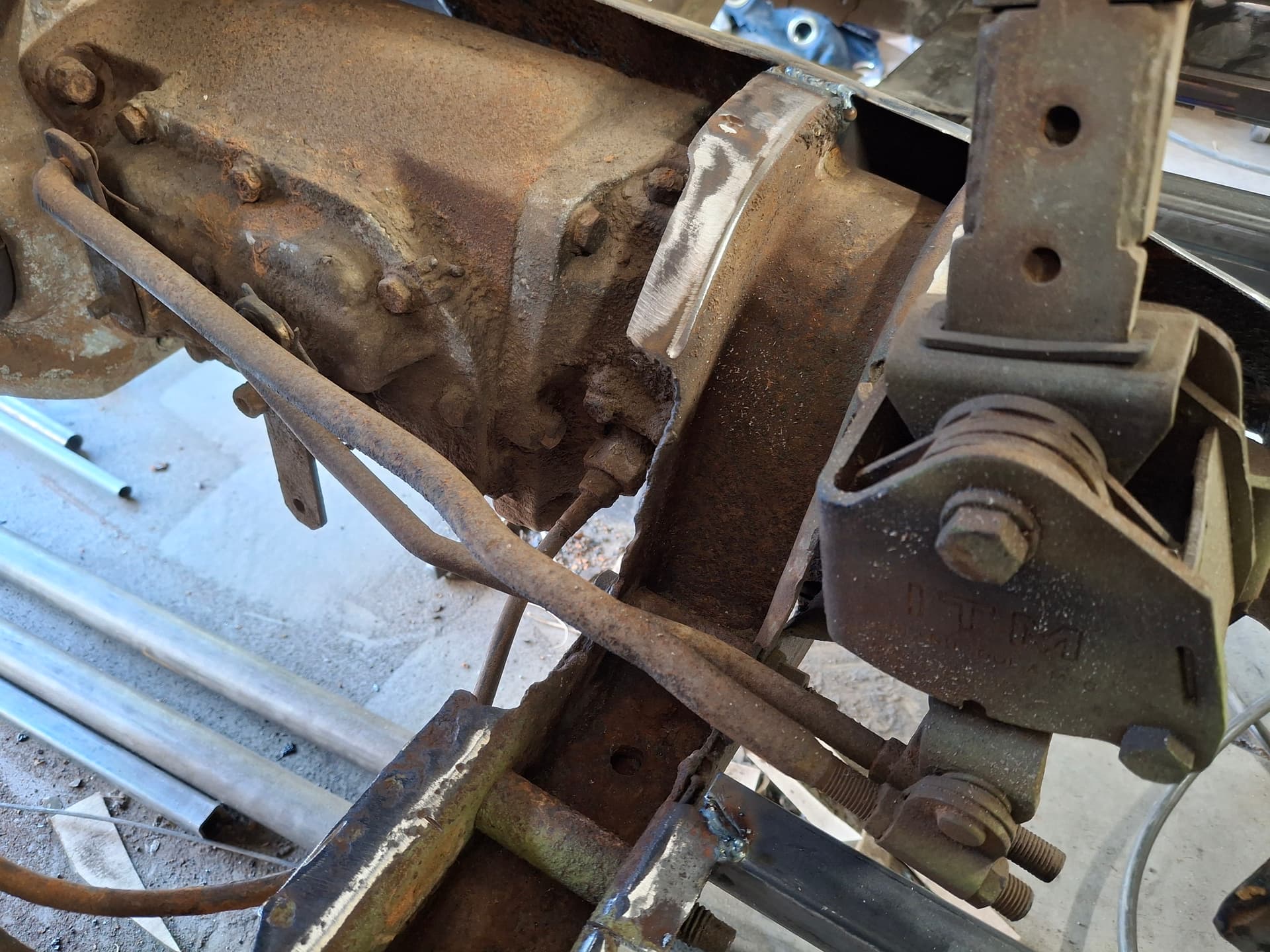
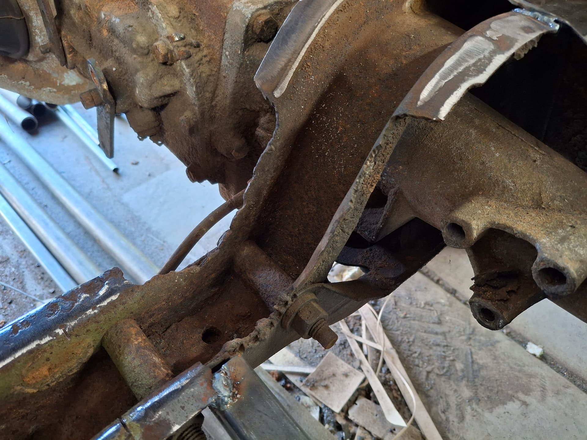
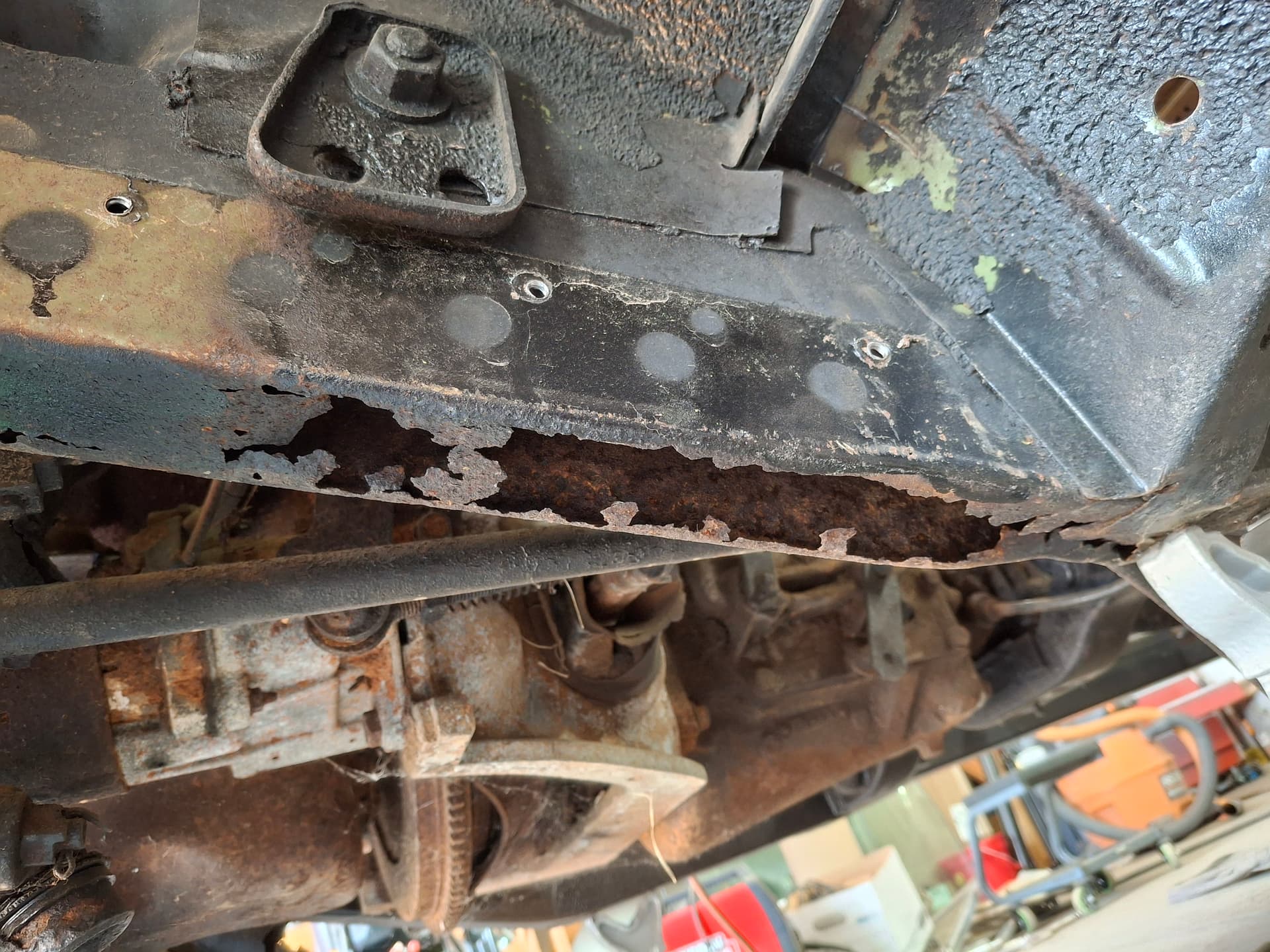
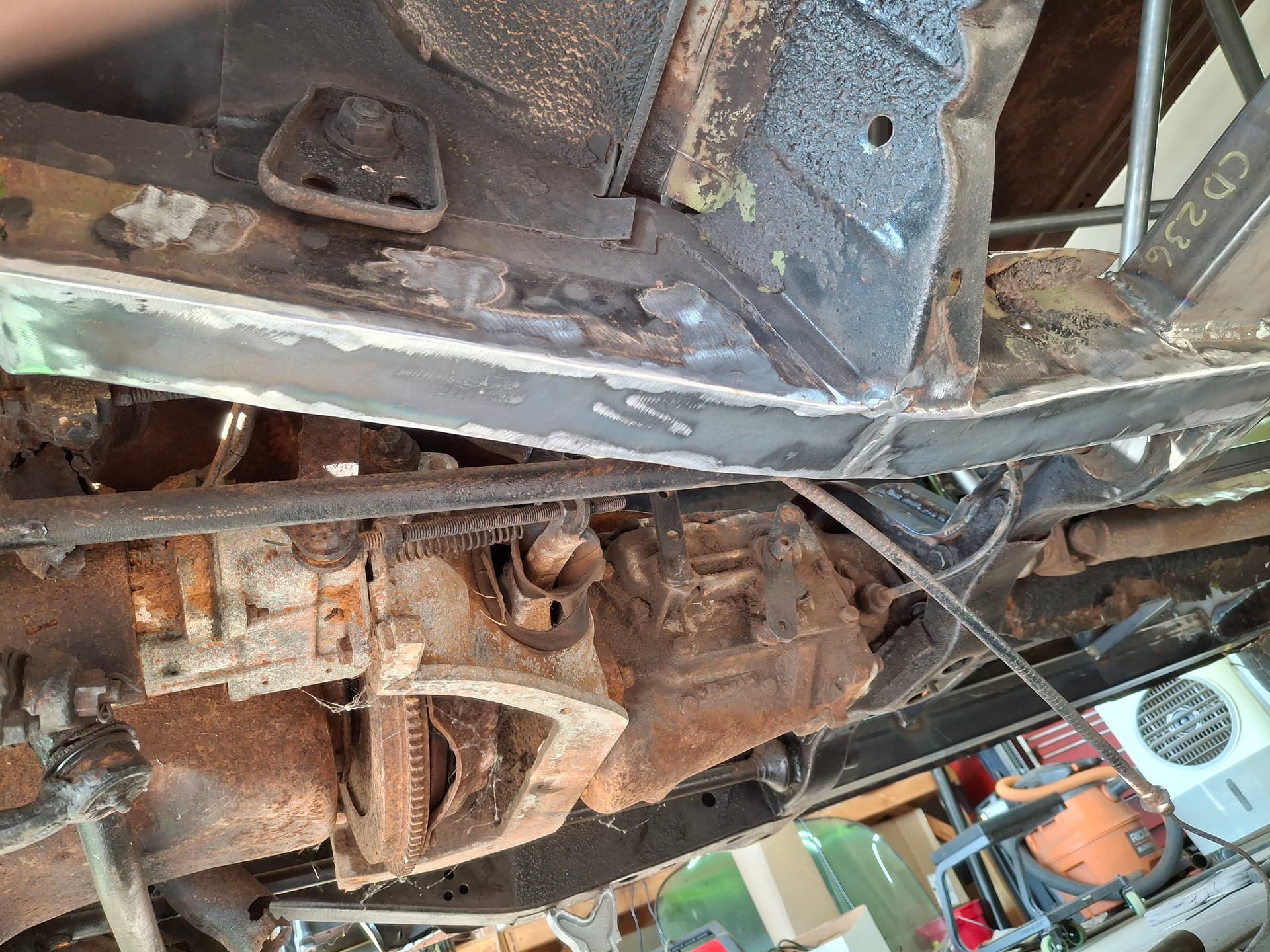
I obtained the 1969 Plymouth Barracuda fastback from a field in Elizabeth, CO last year. It’s a factory LA (small block) 318 V8 four-speed manual car, one of 509 produced. While the body has extremely little rot (a couple typical holes around the rear window and in the bottom of the fenders) and is pretty straight, the car has been neglected for decades with much of the interior stripped, making it a prime candidate for an RMVR race car. I will register it for the street and have the bare-bones necessities so I can do light tuning and drive to local cruise nights/meet-ups to promote RMVR.

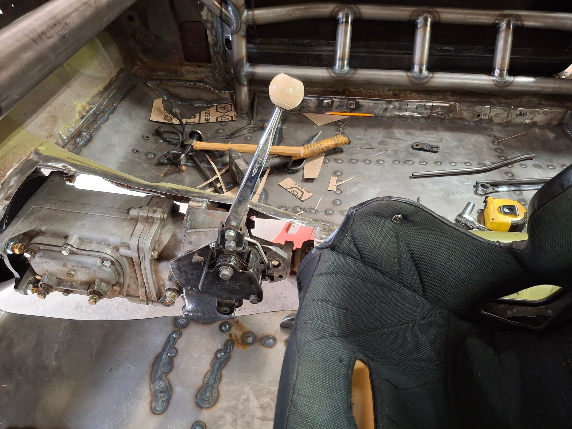
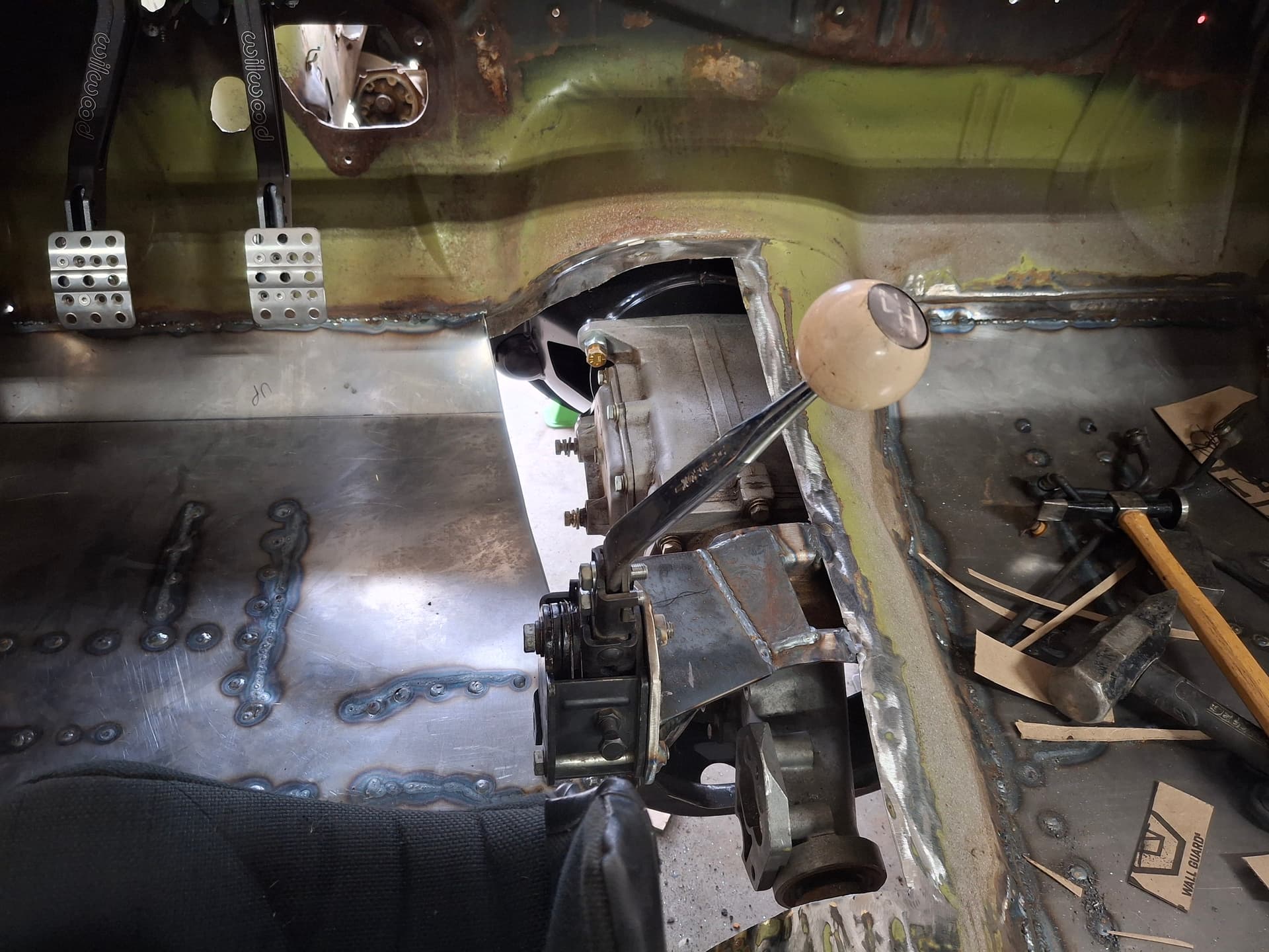
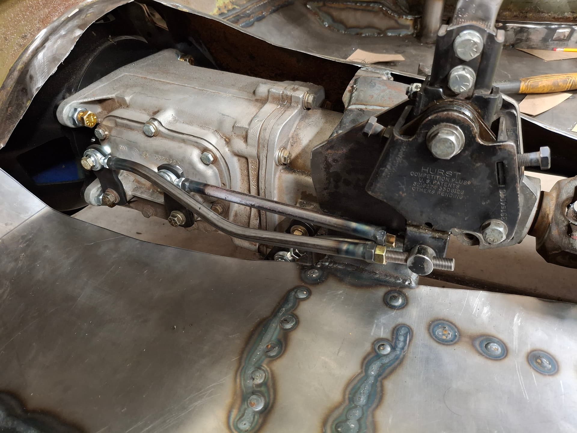
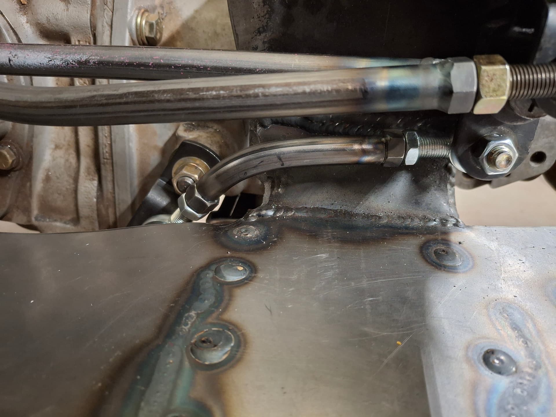
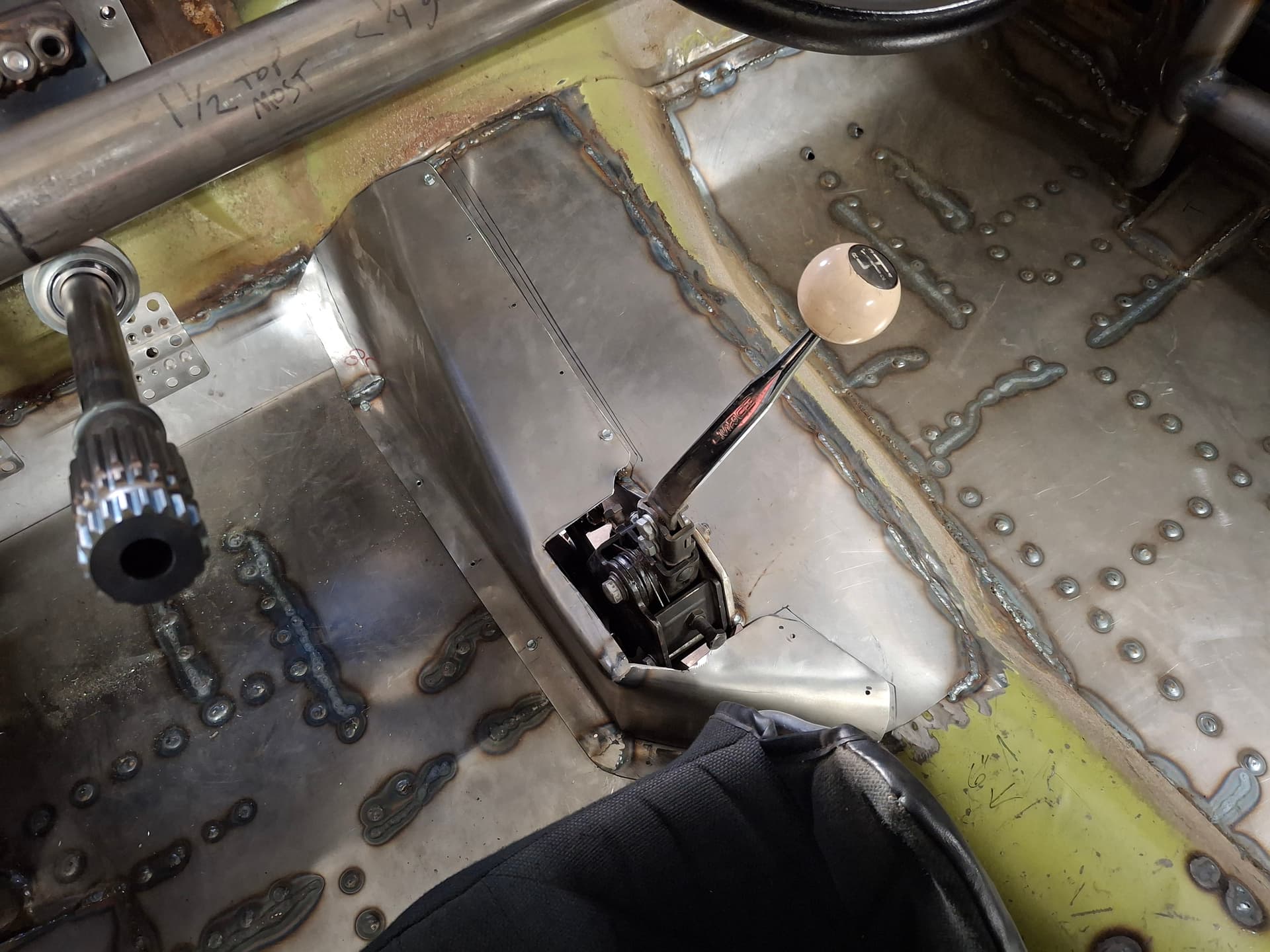
The plan is to build it to our 1981 GCR for the GT-1 class. I’ll be punching out the engine to 364 c.i.d. (class rule limits it to 366), and the car will get all-wheel disc brakes. It will maintain a four-speed transmission.

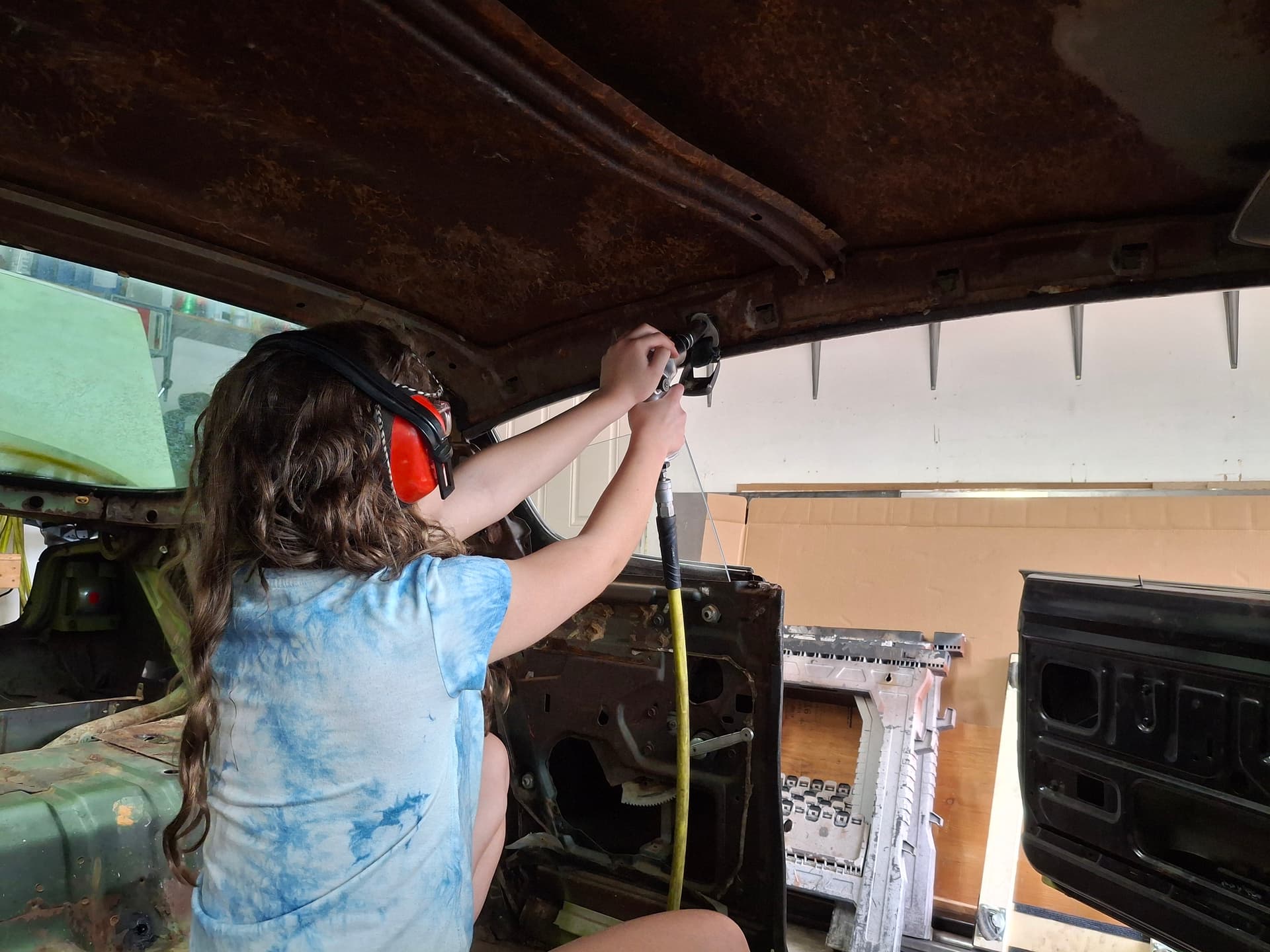
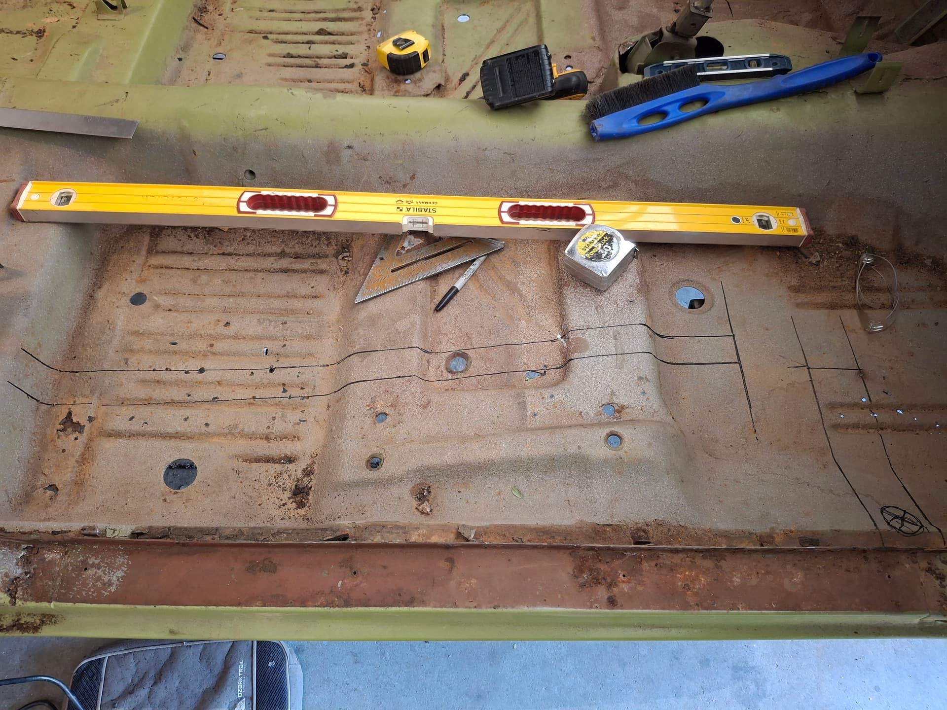
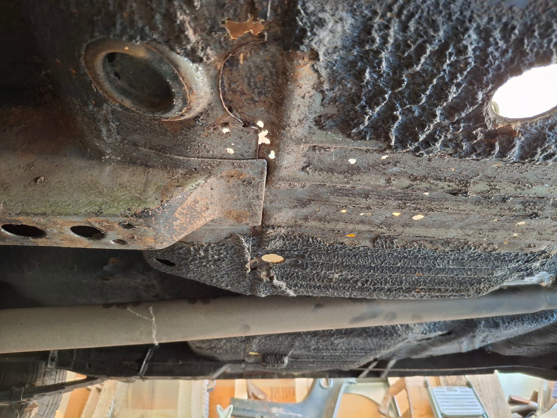
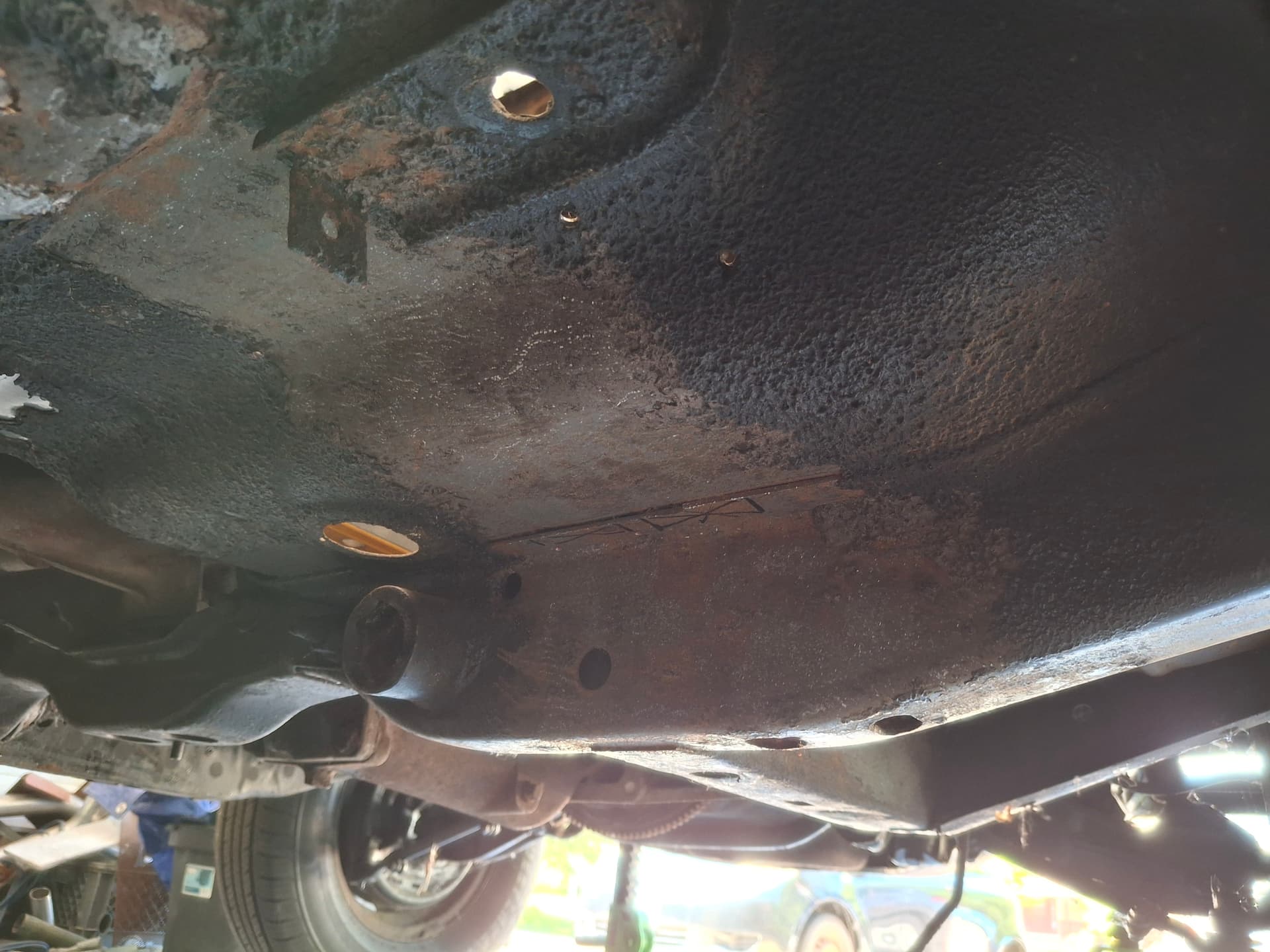
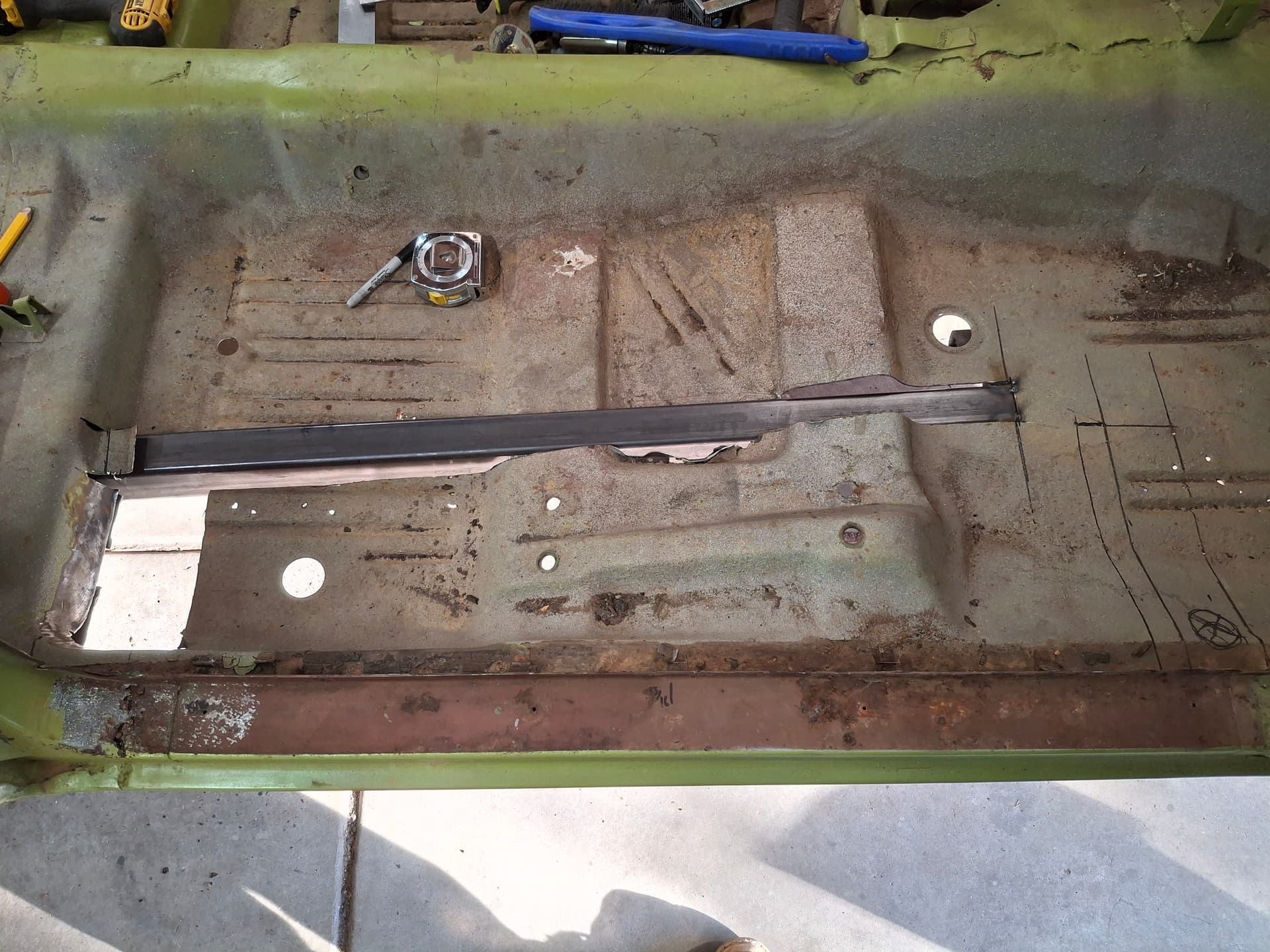
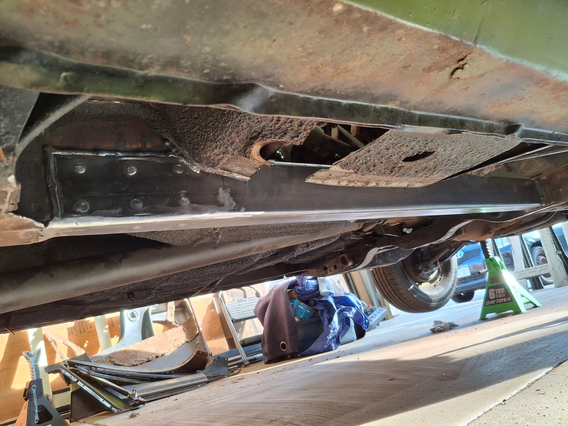
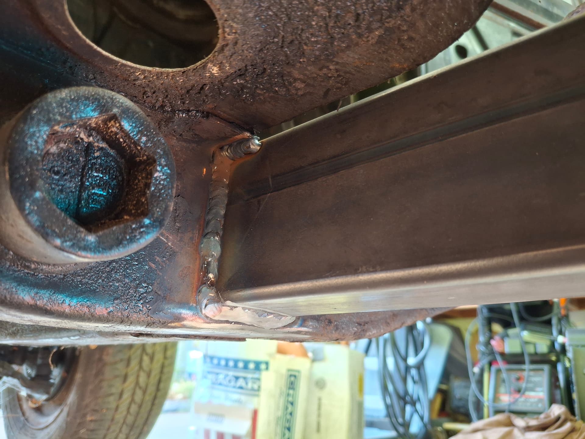
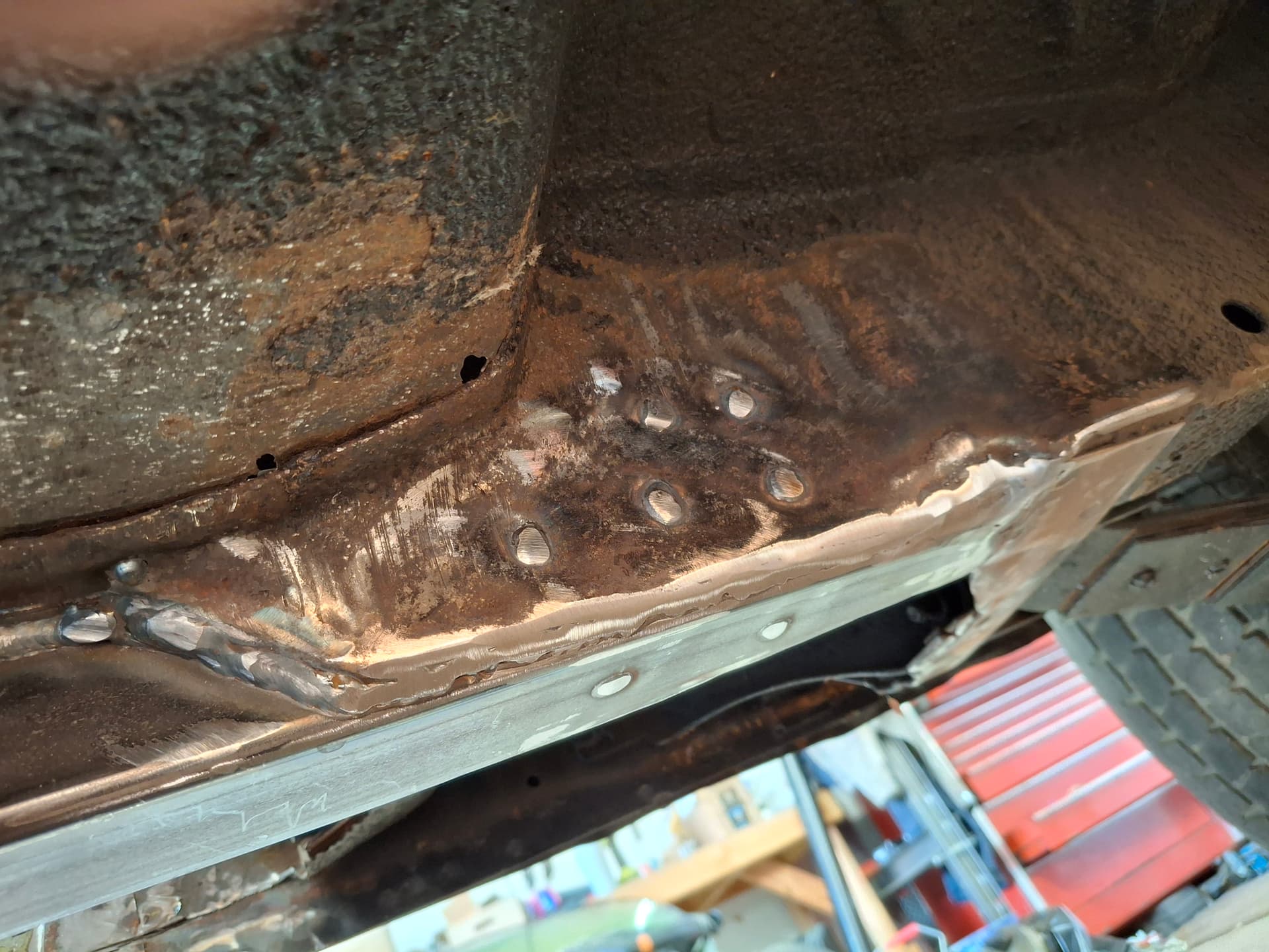
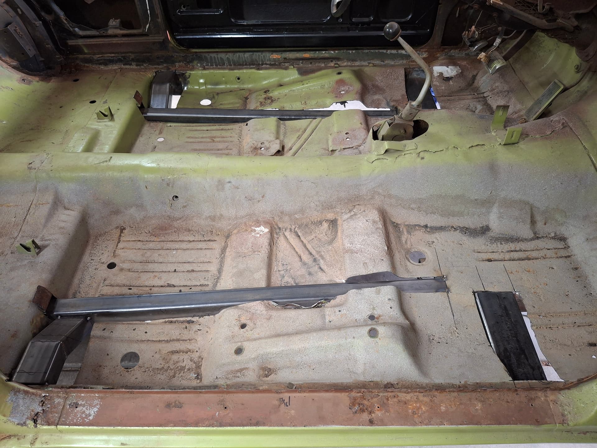
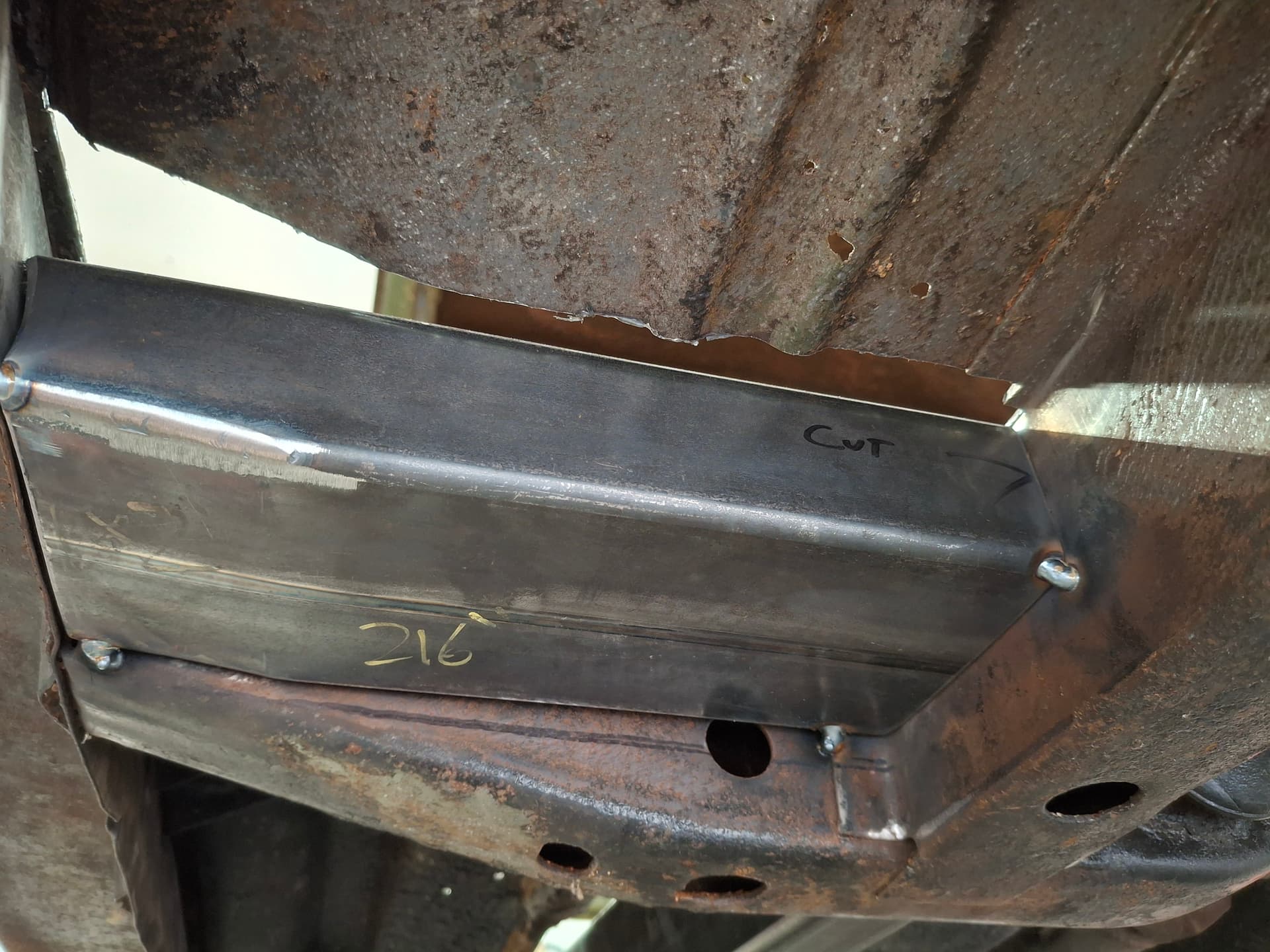
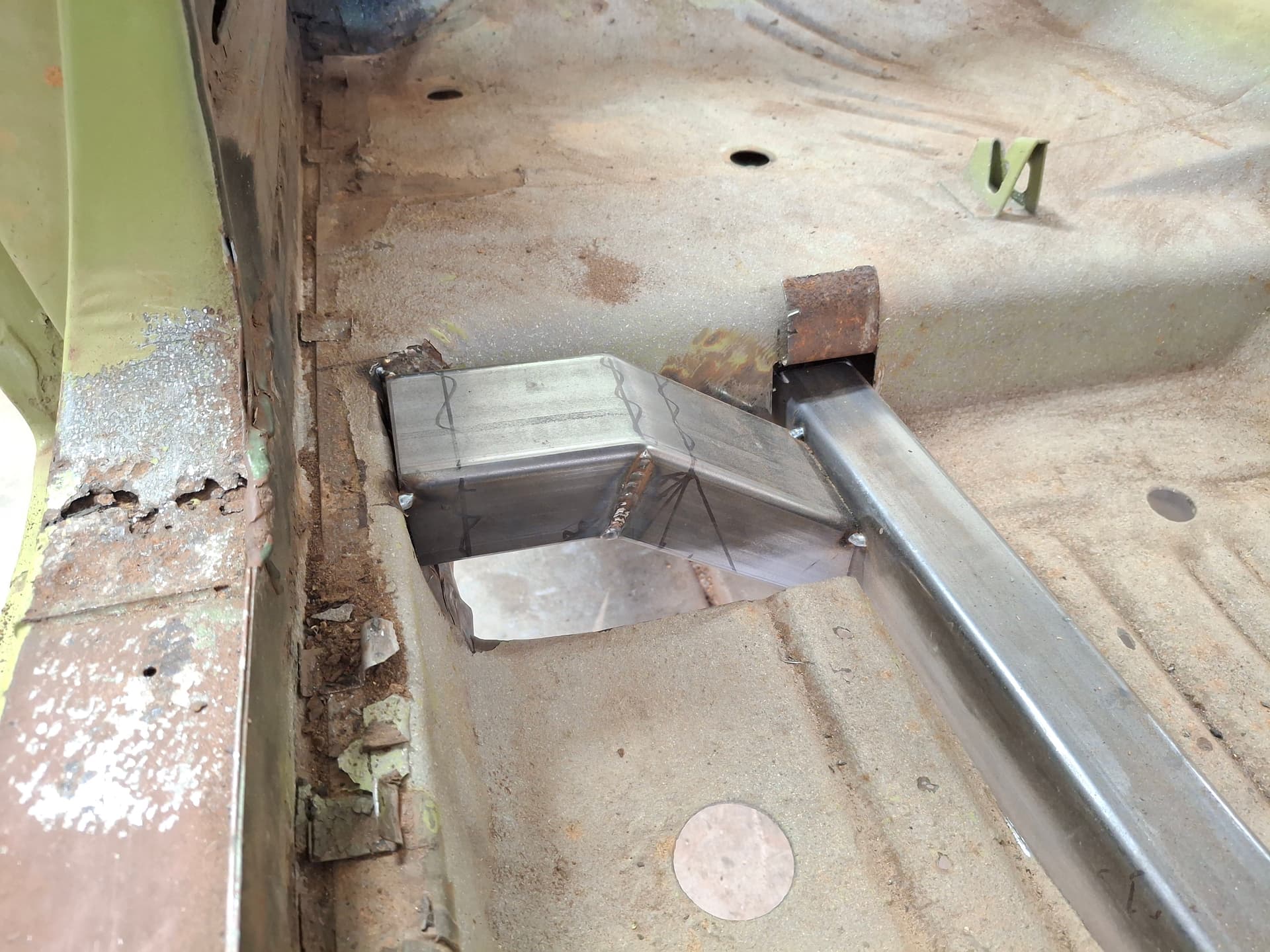
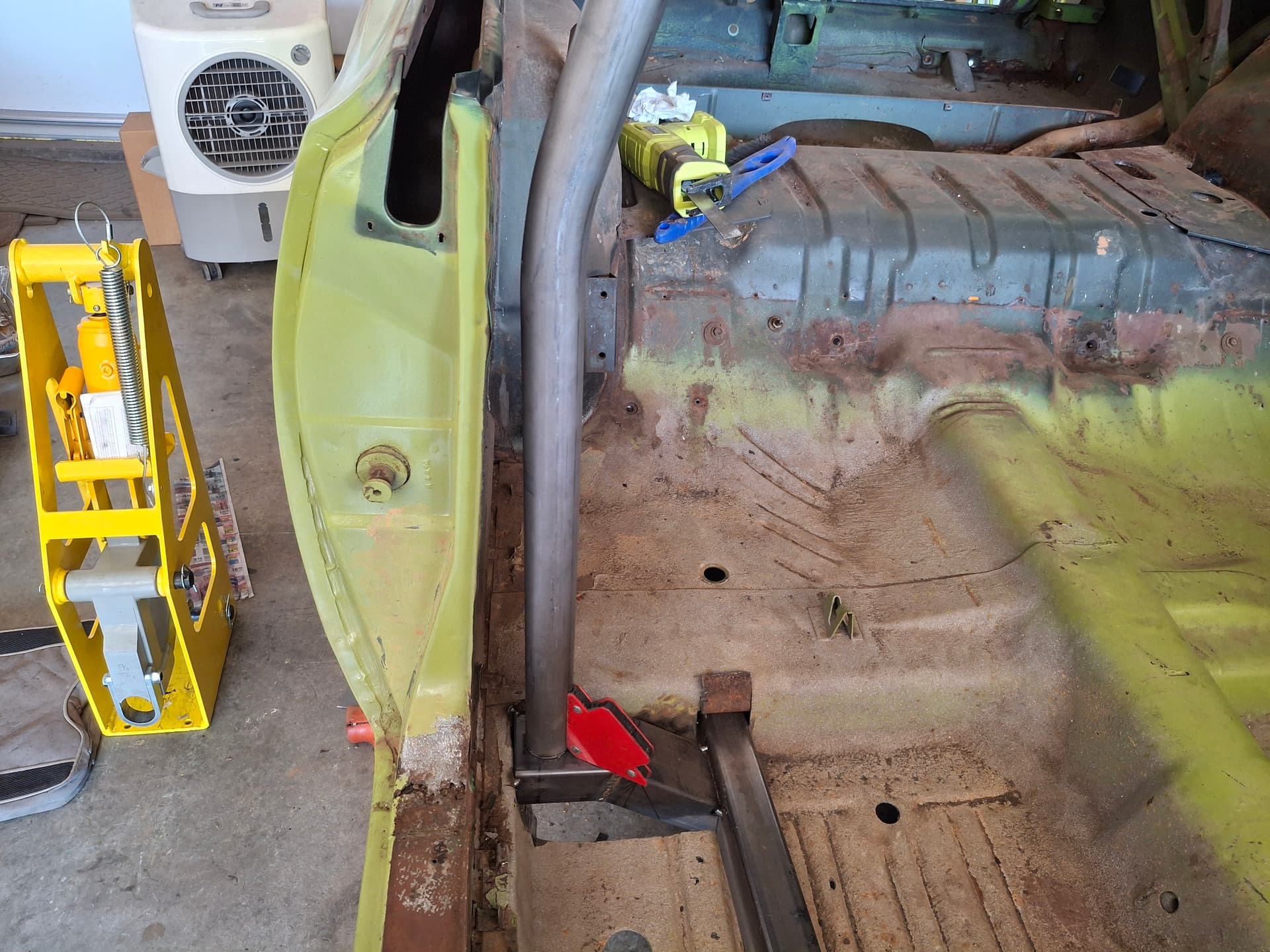
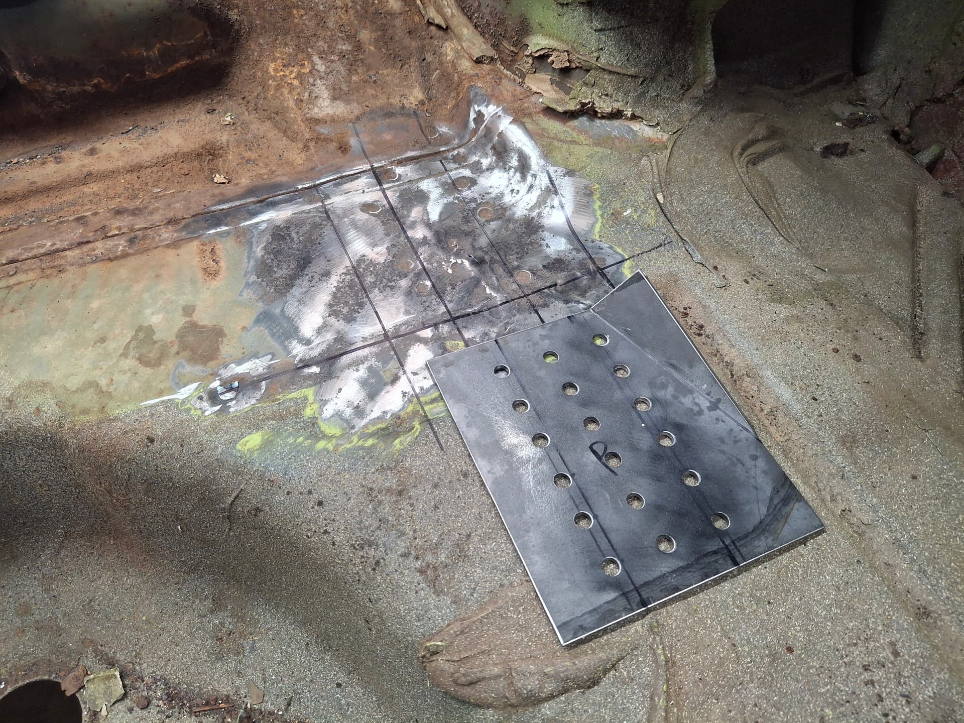
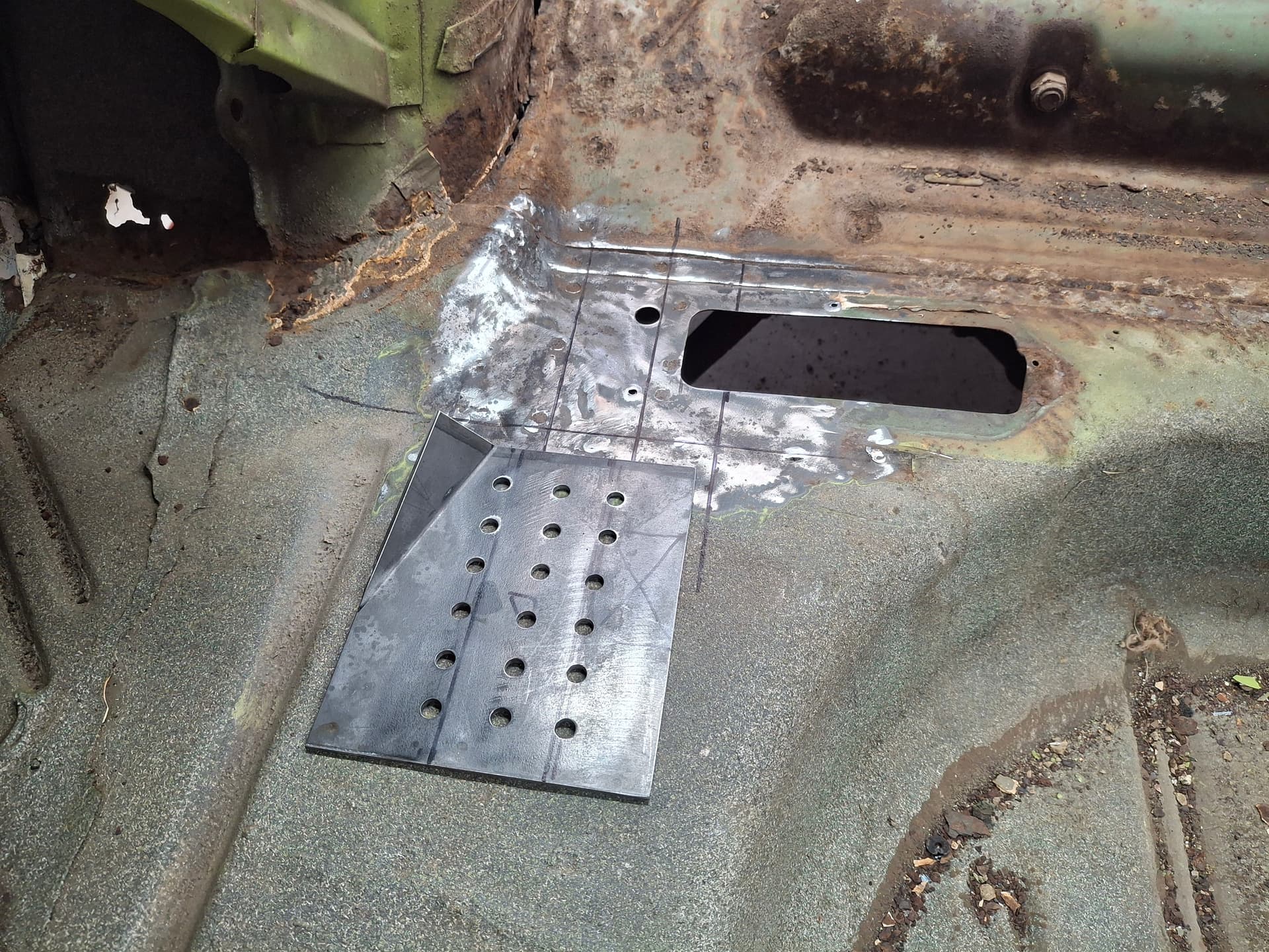
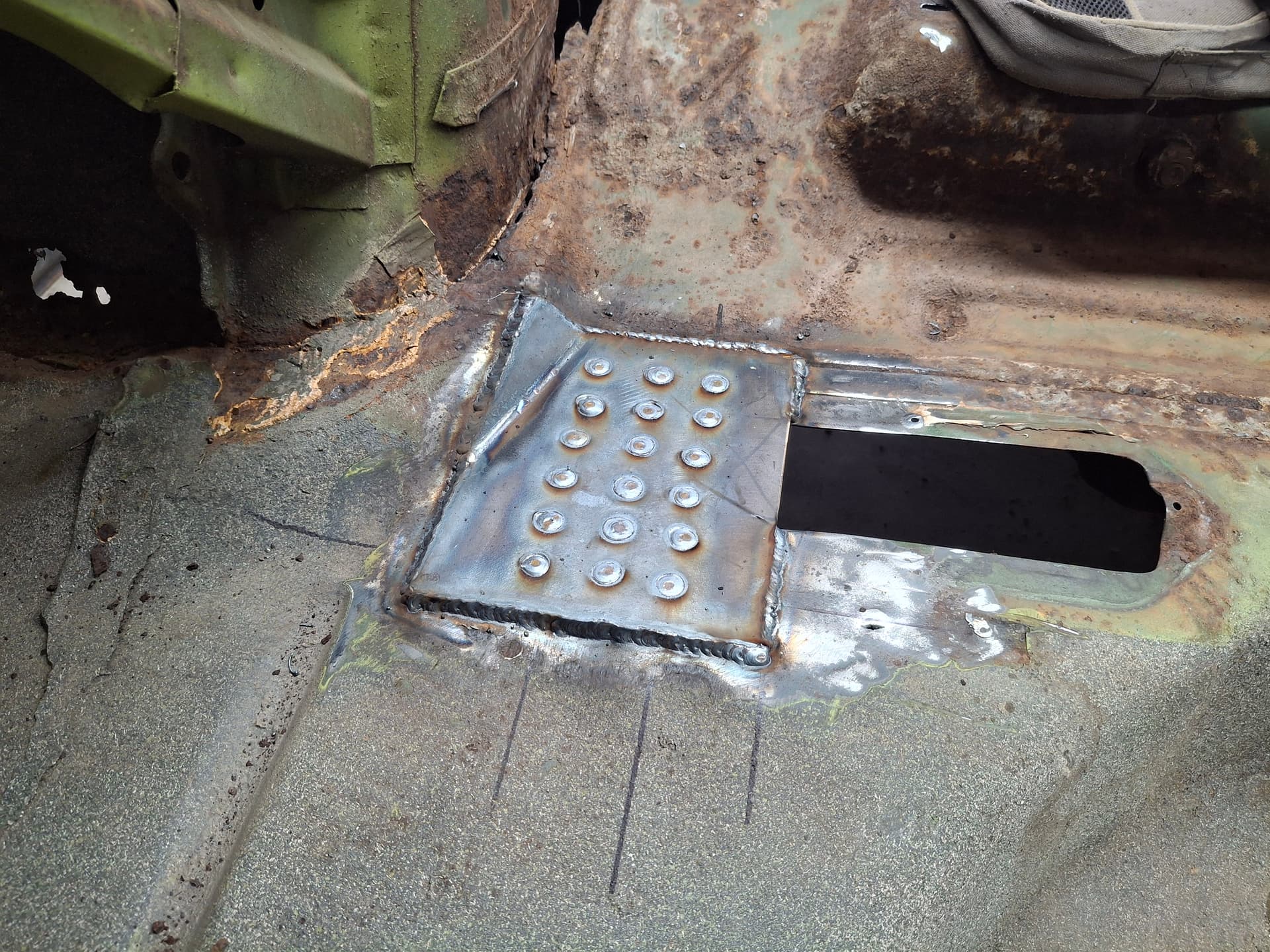
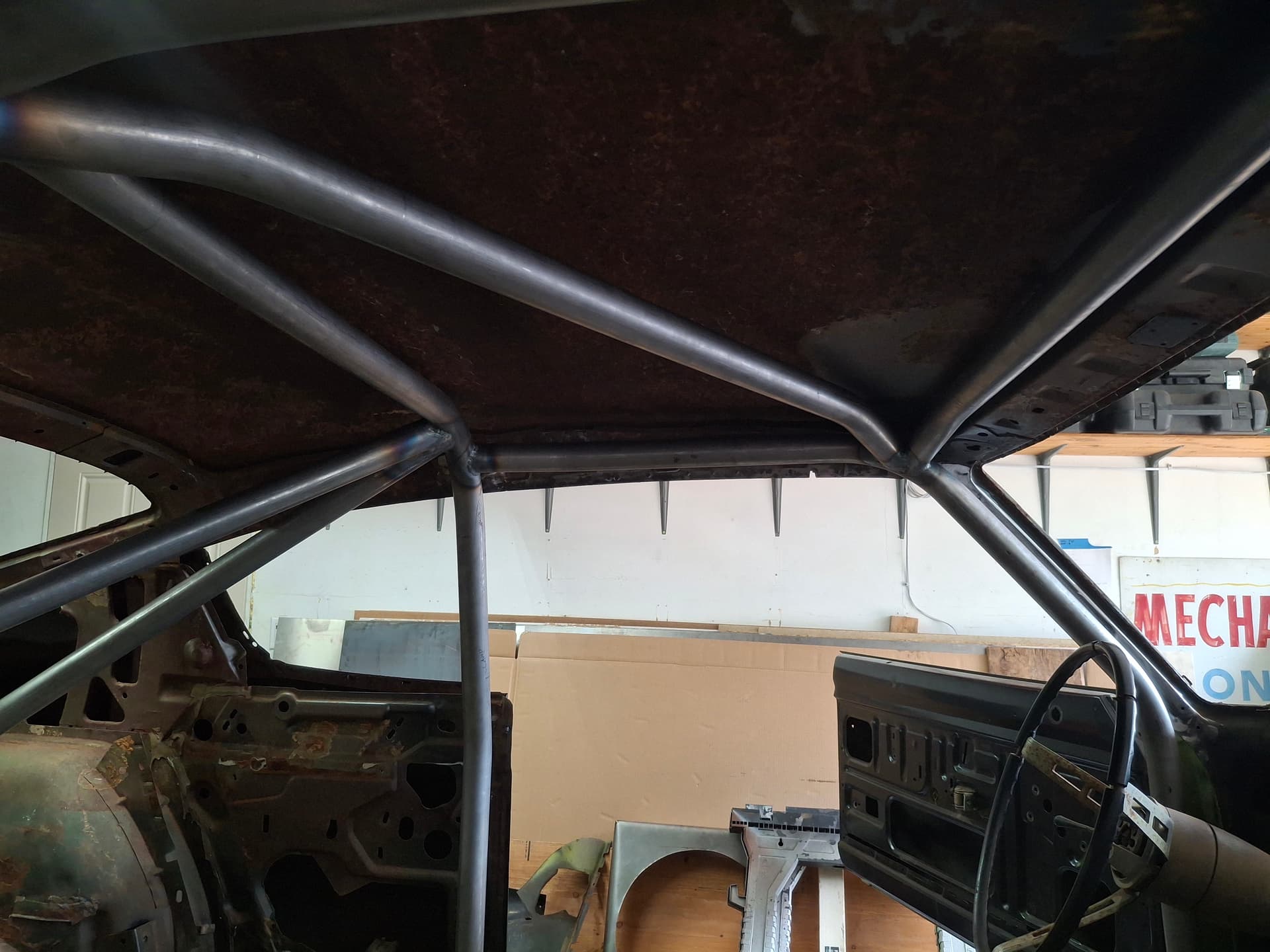
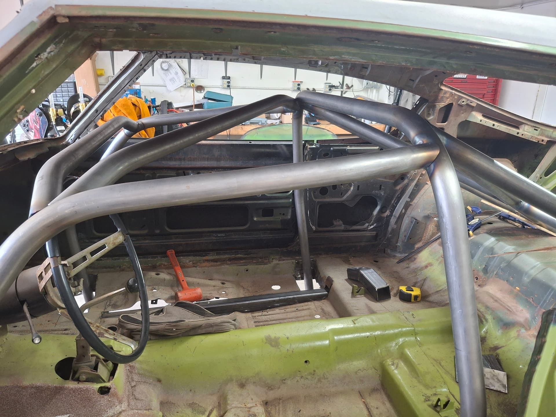
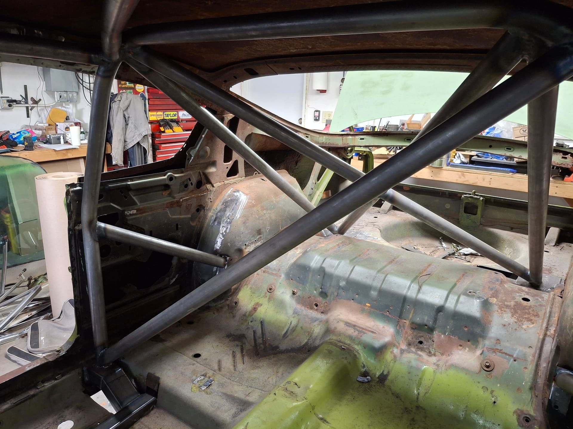
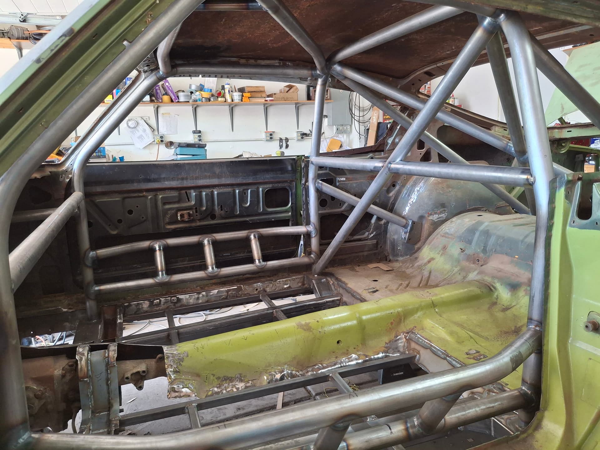
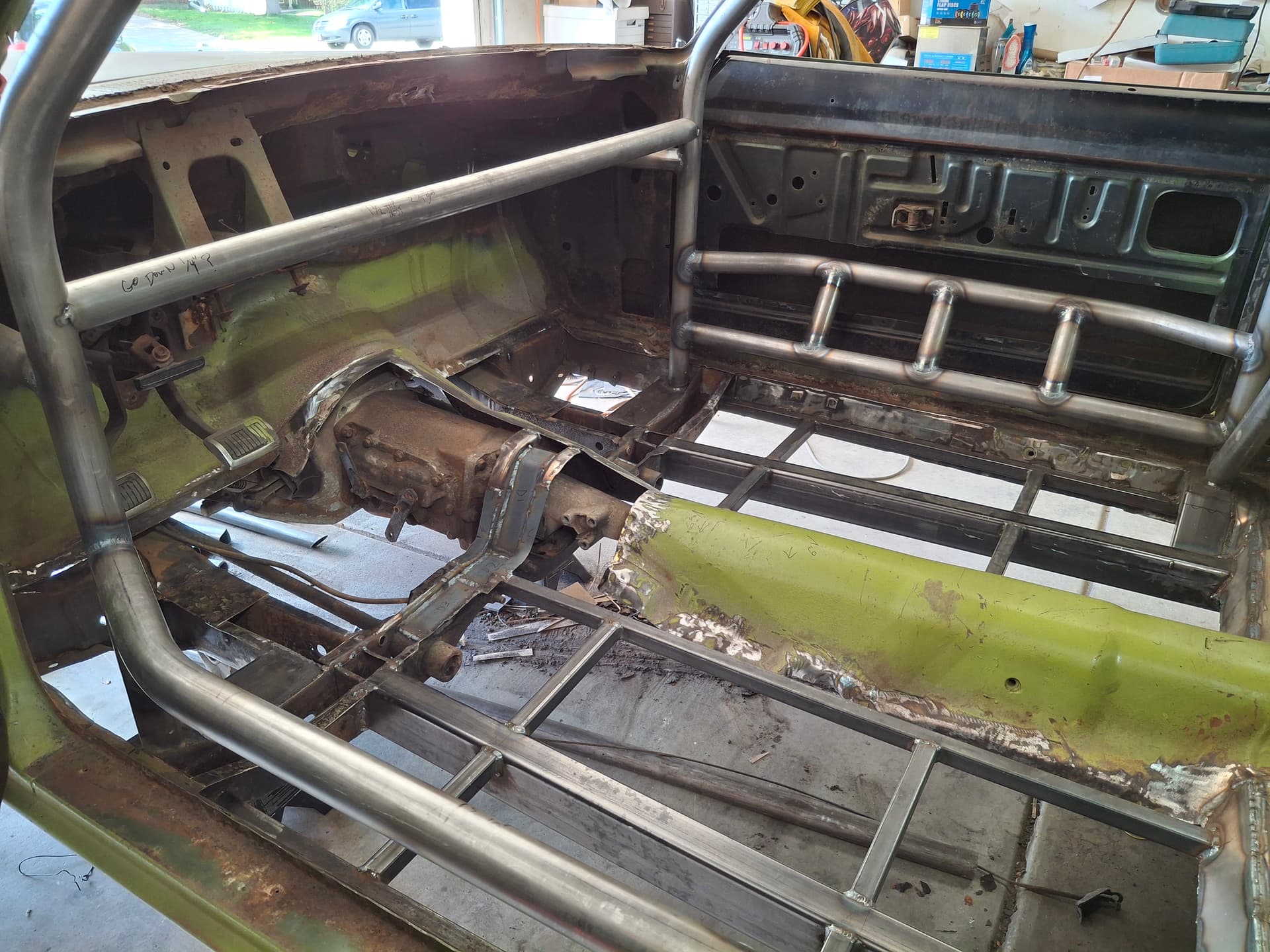
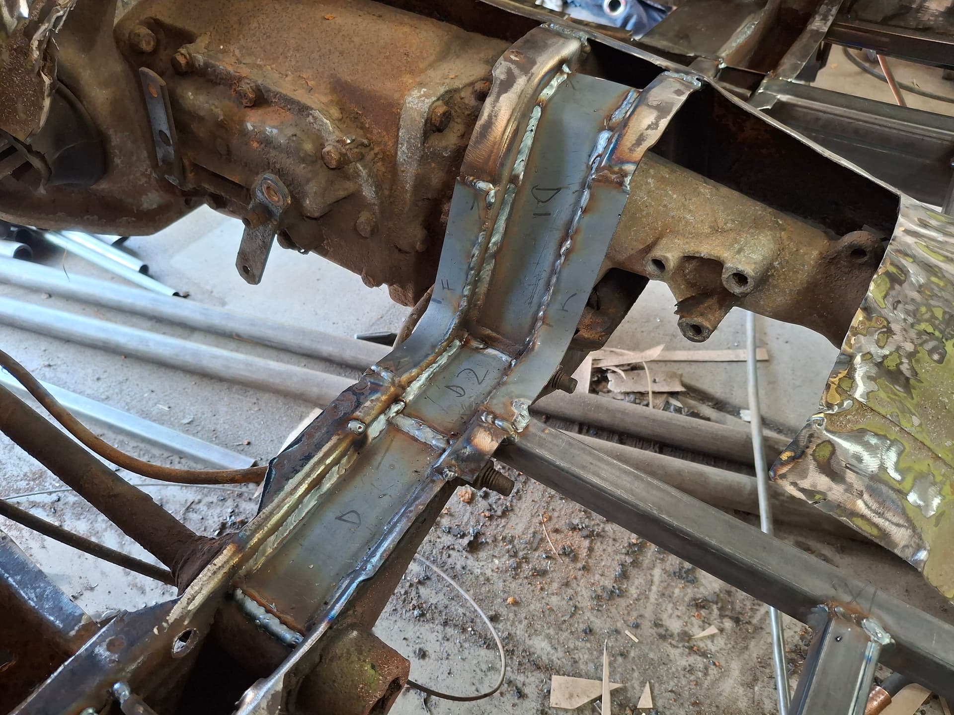
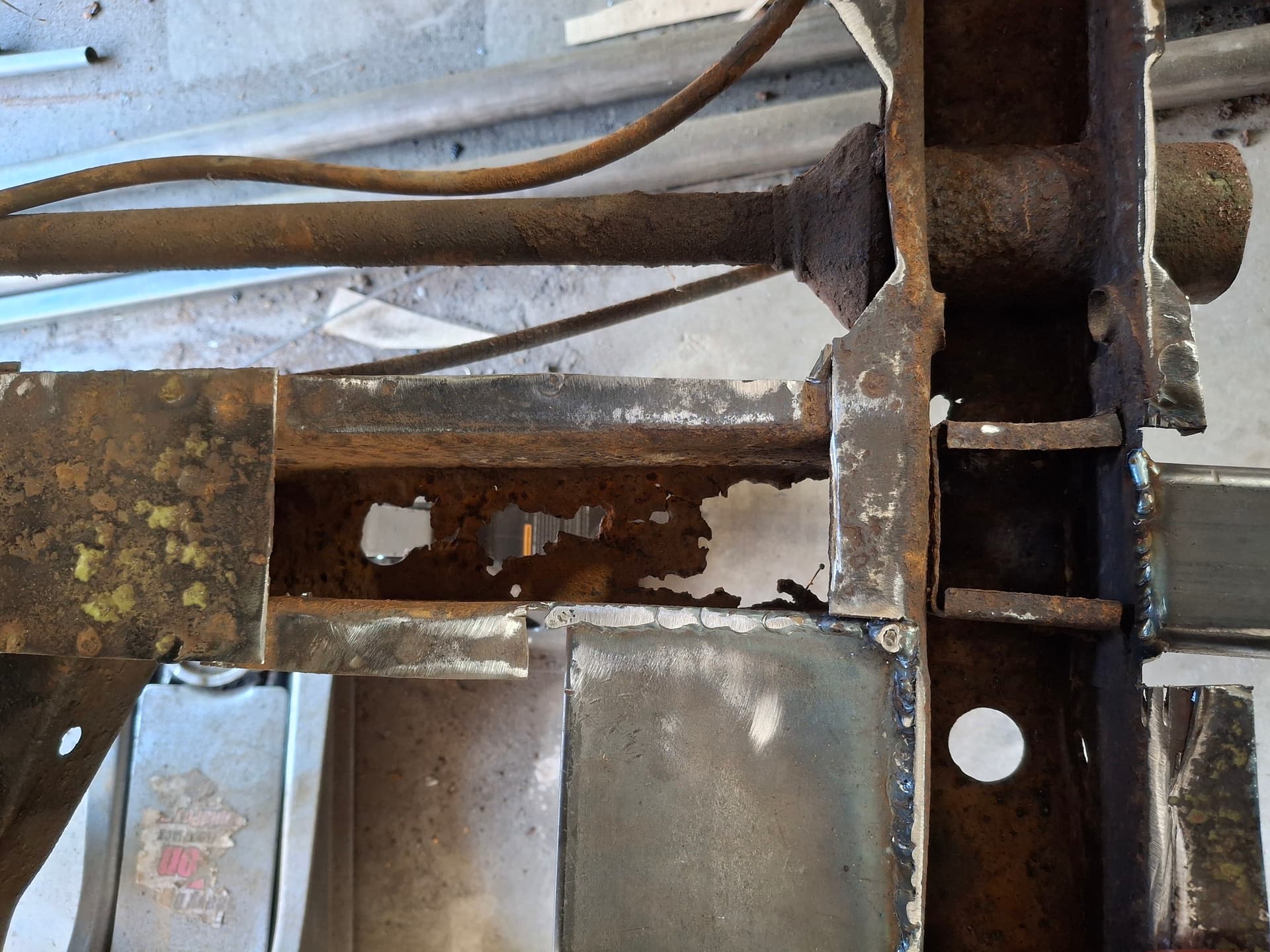
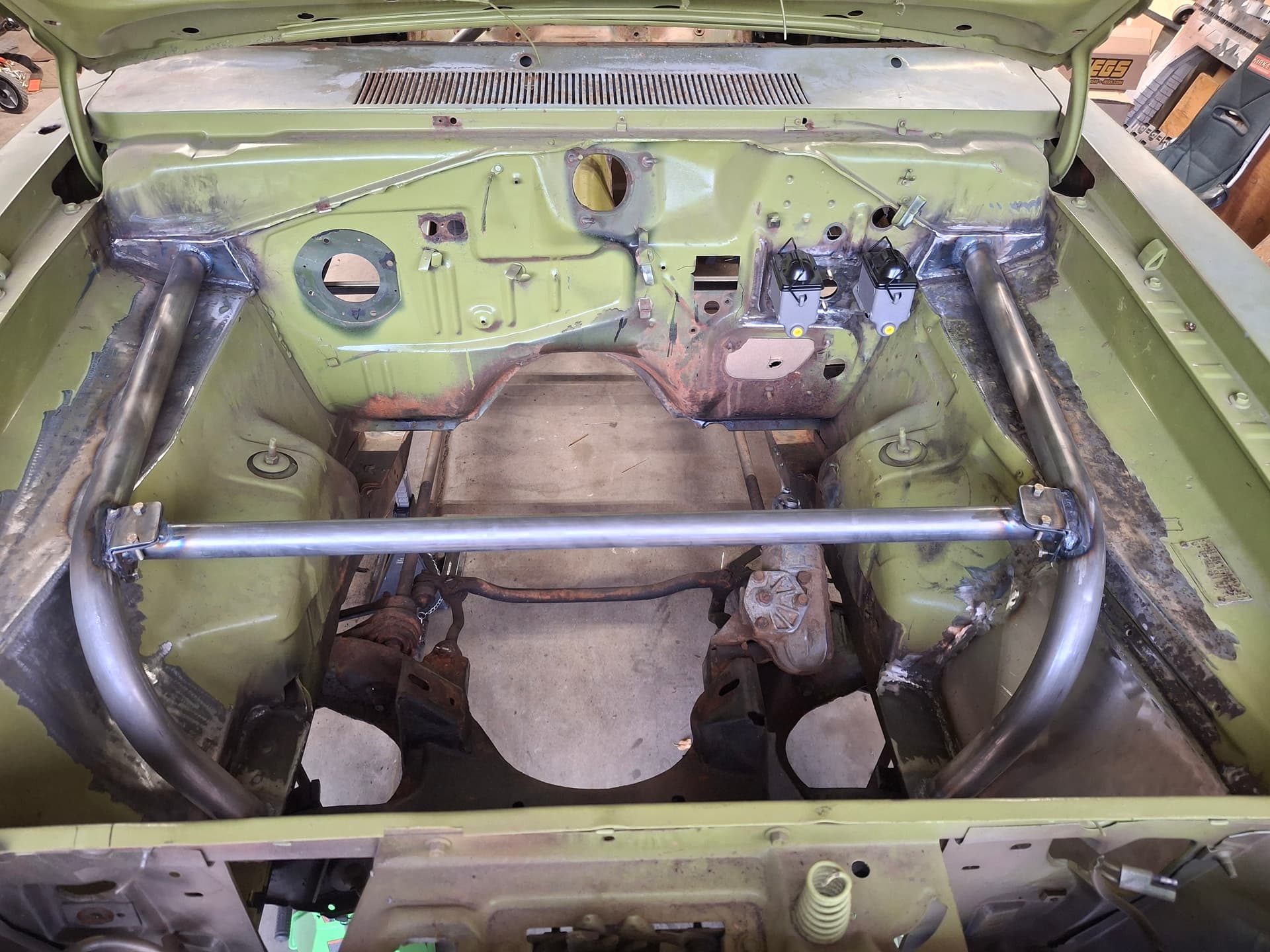
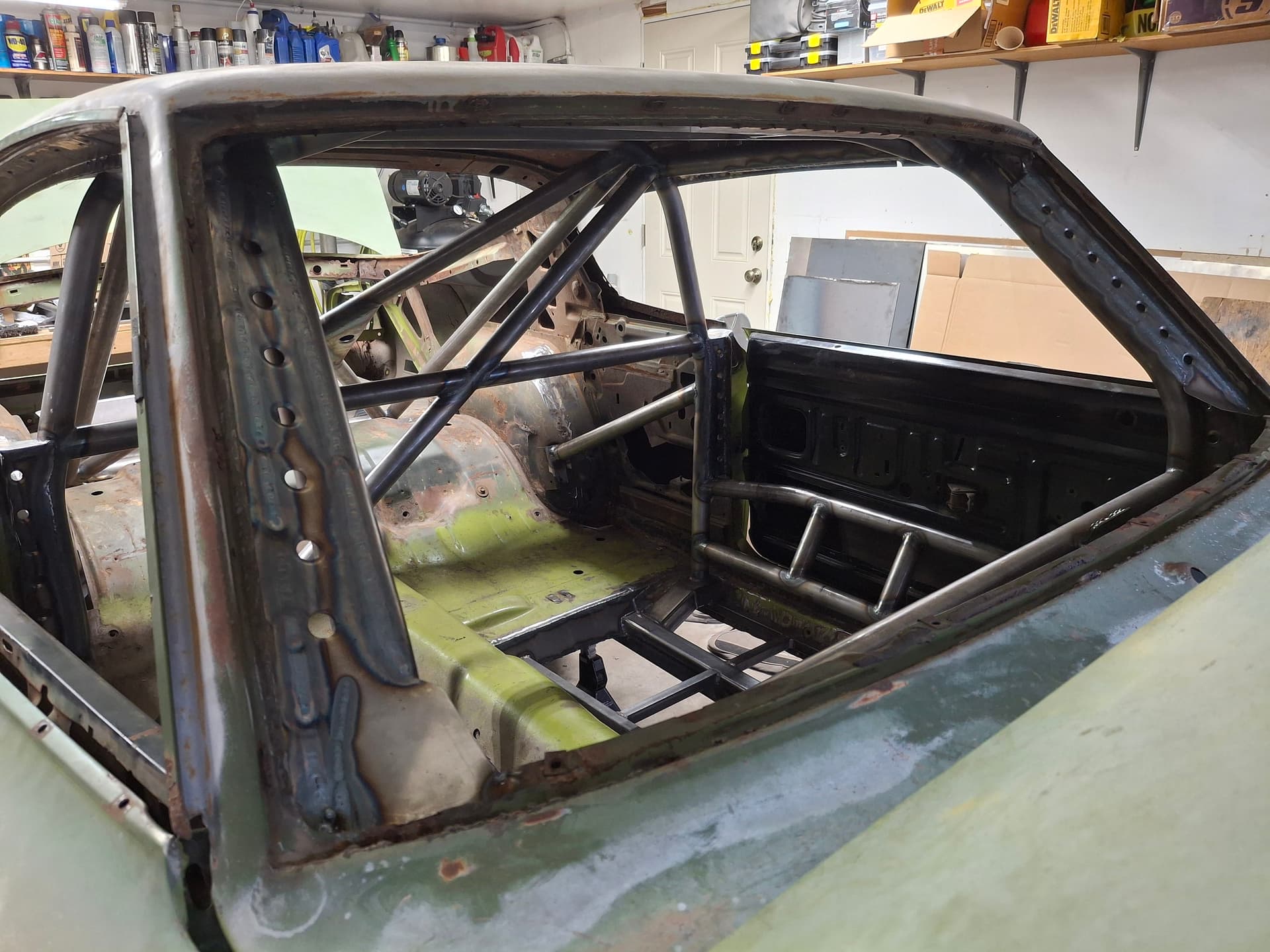
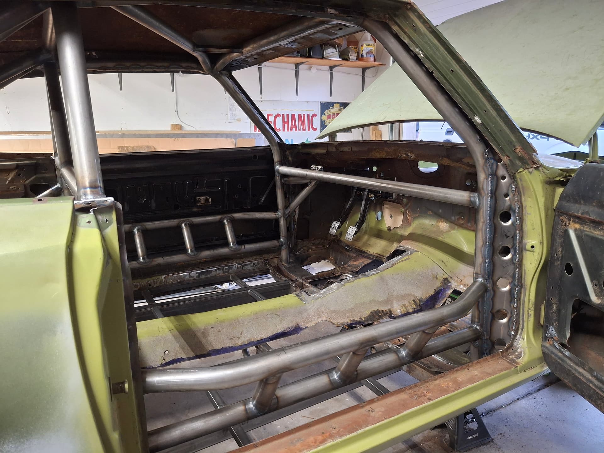
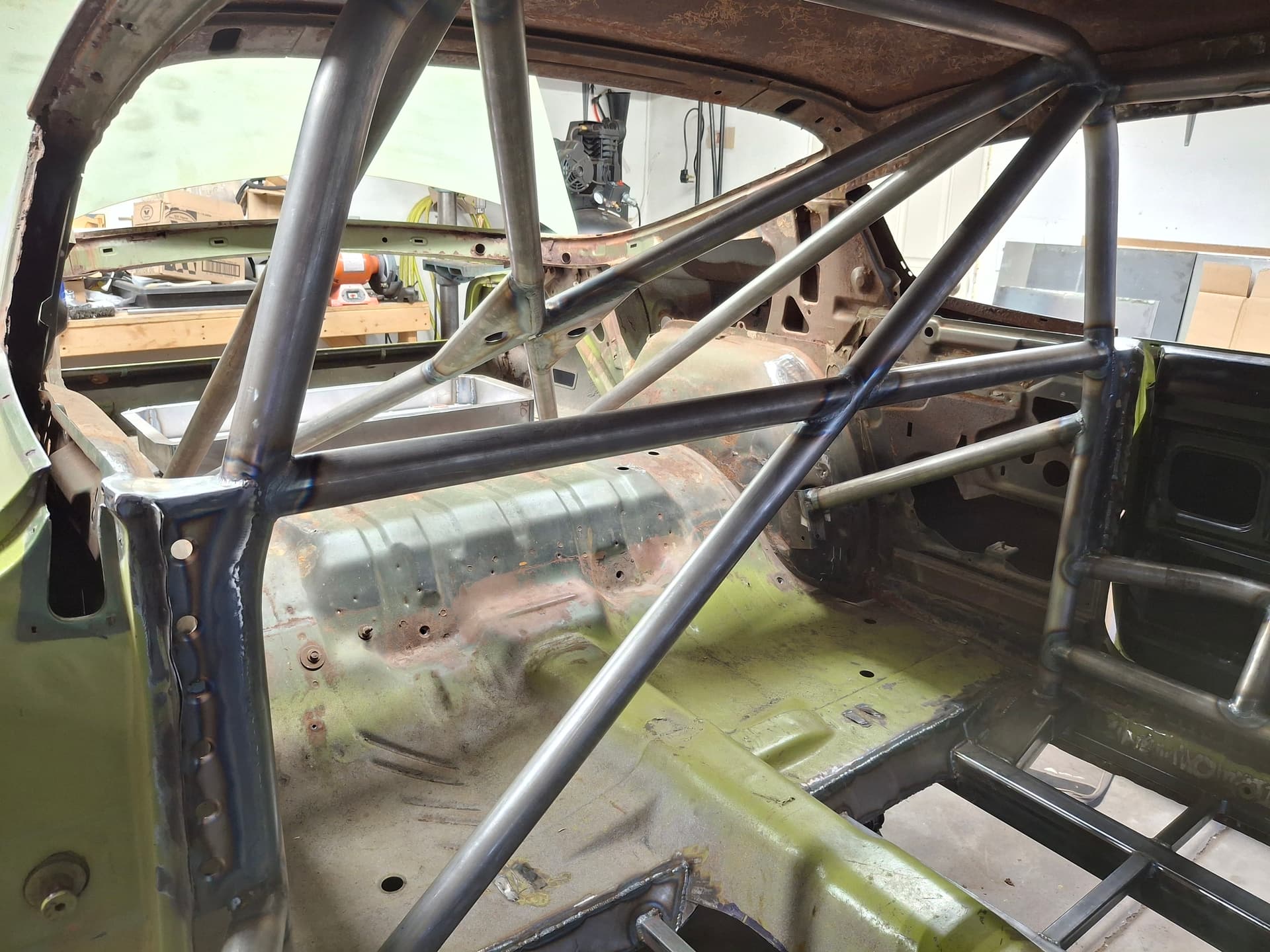
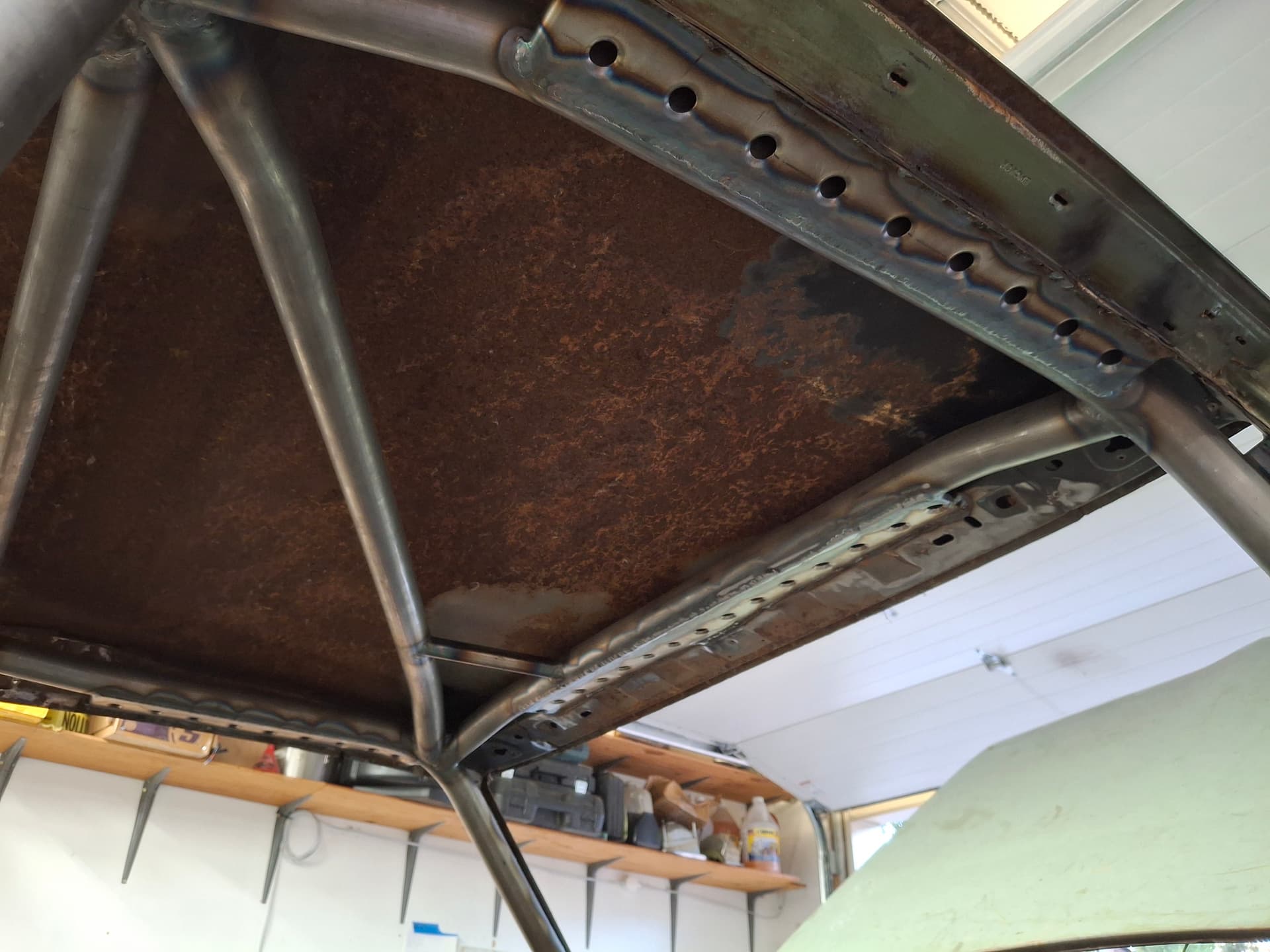
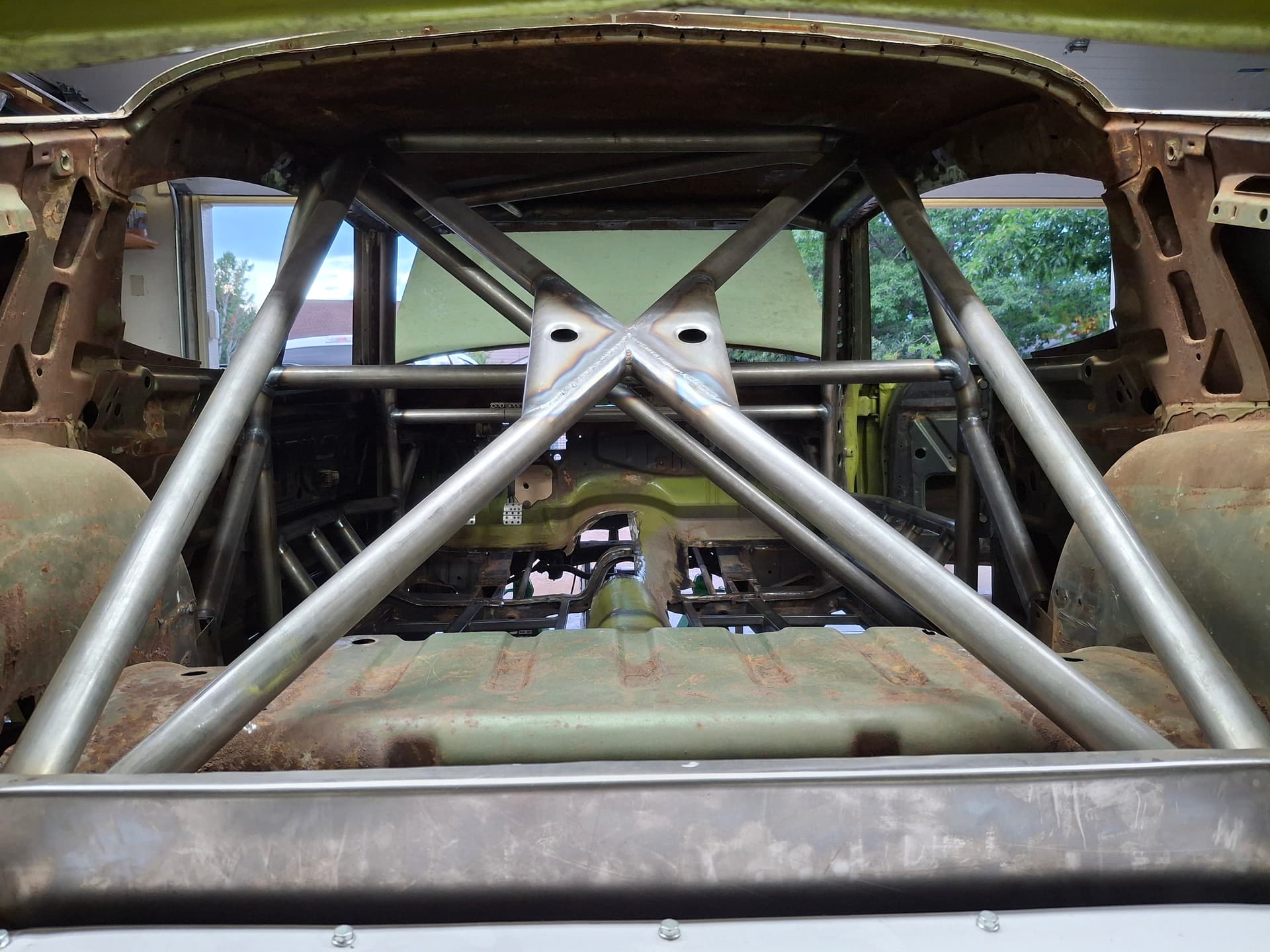
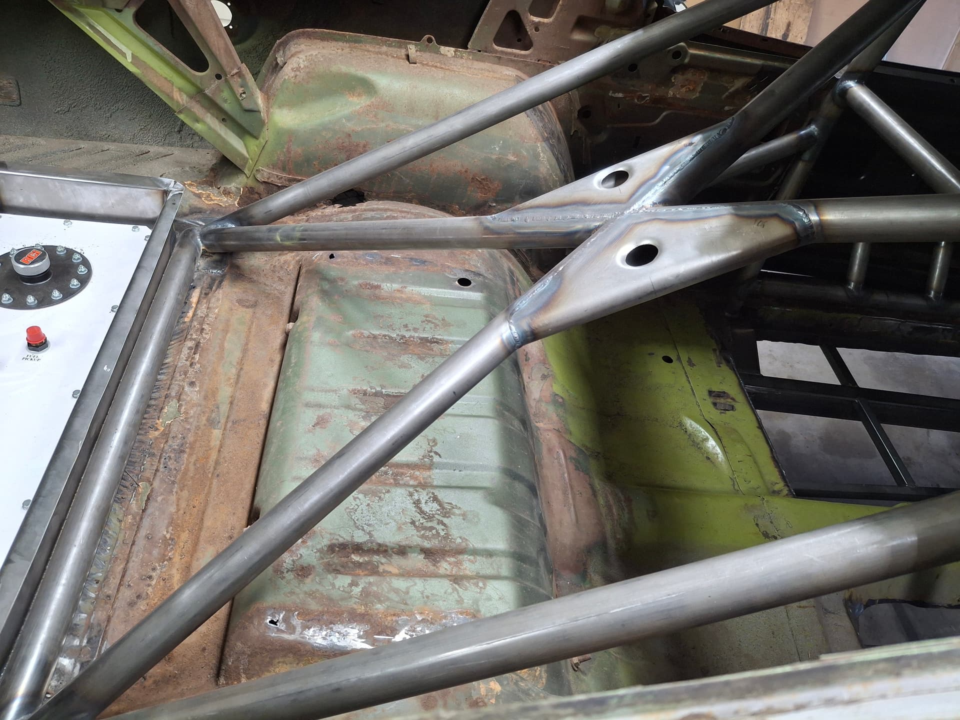
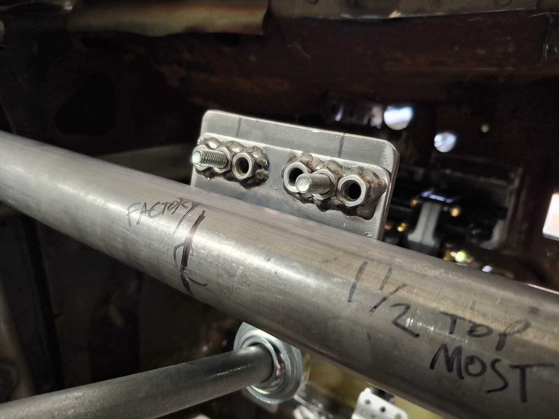
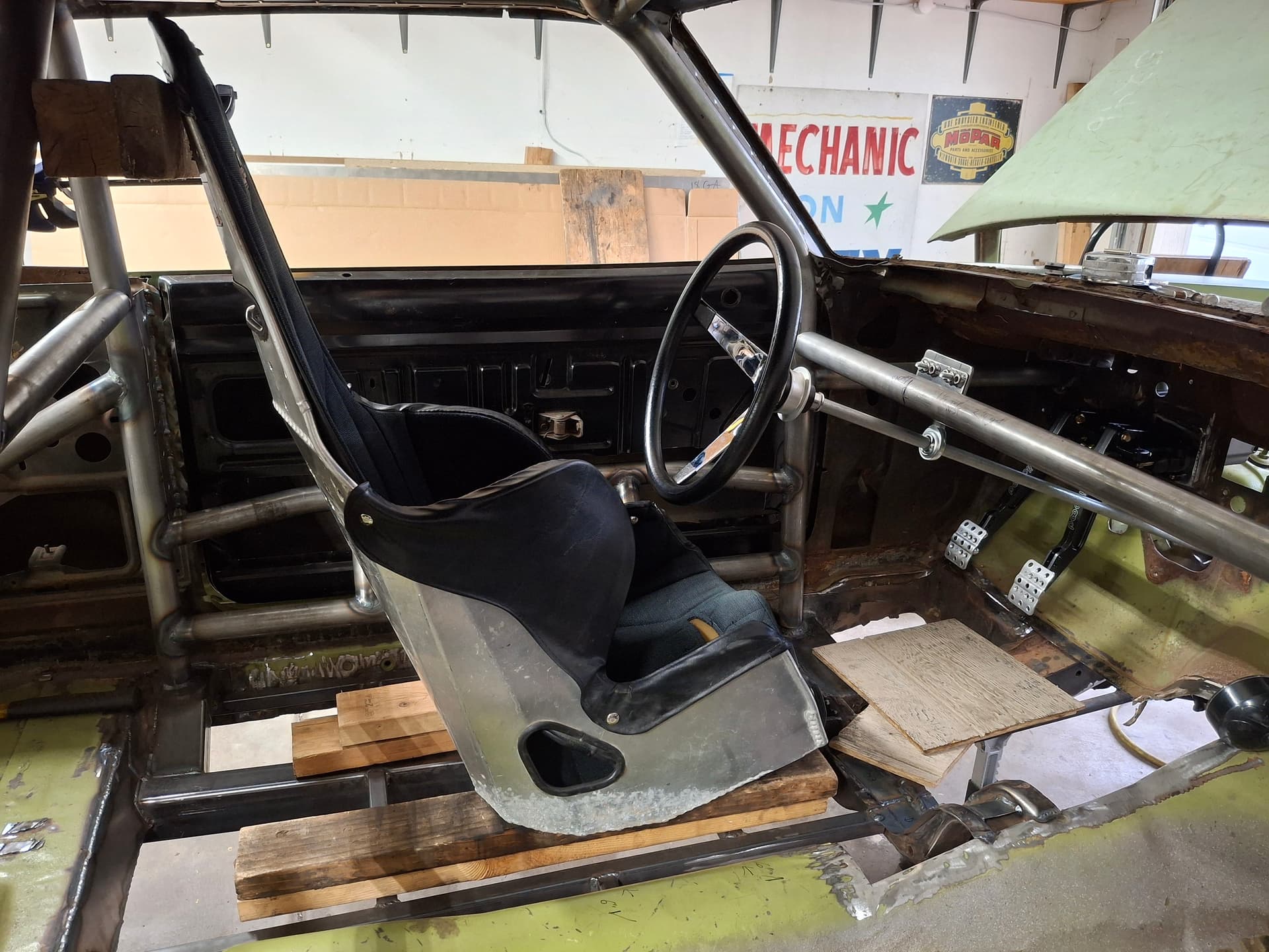
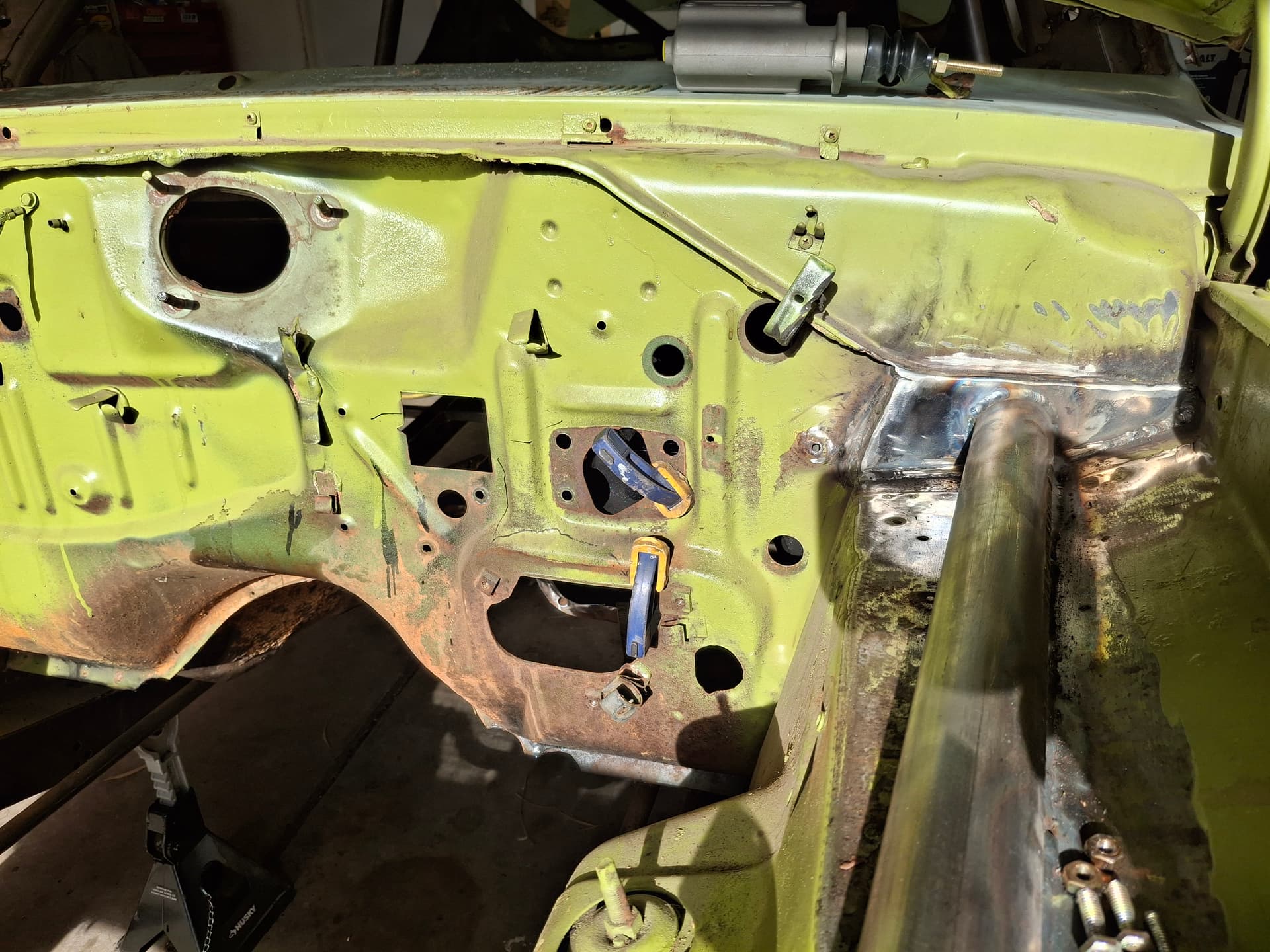
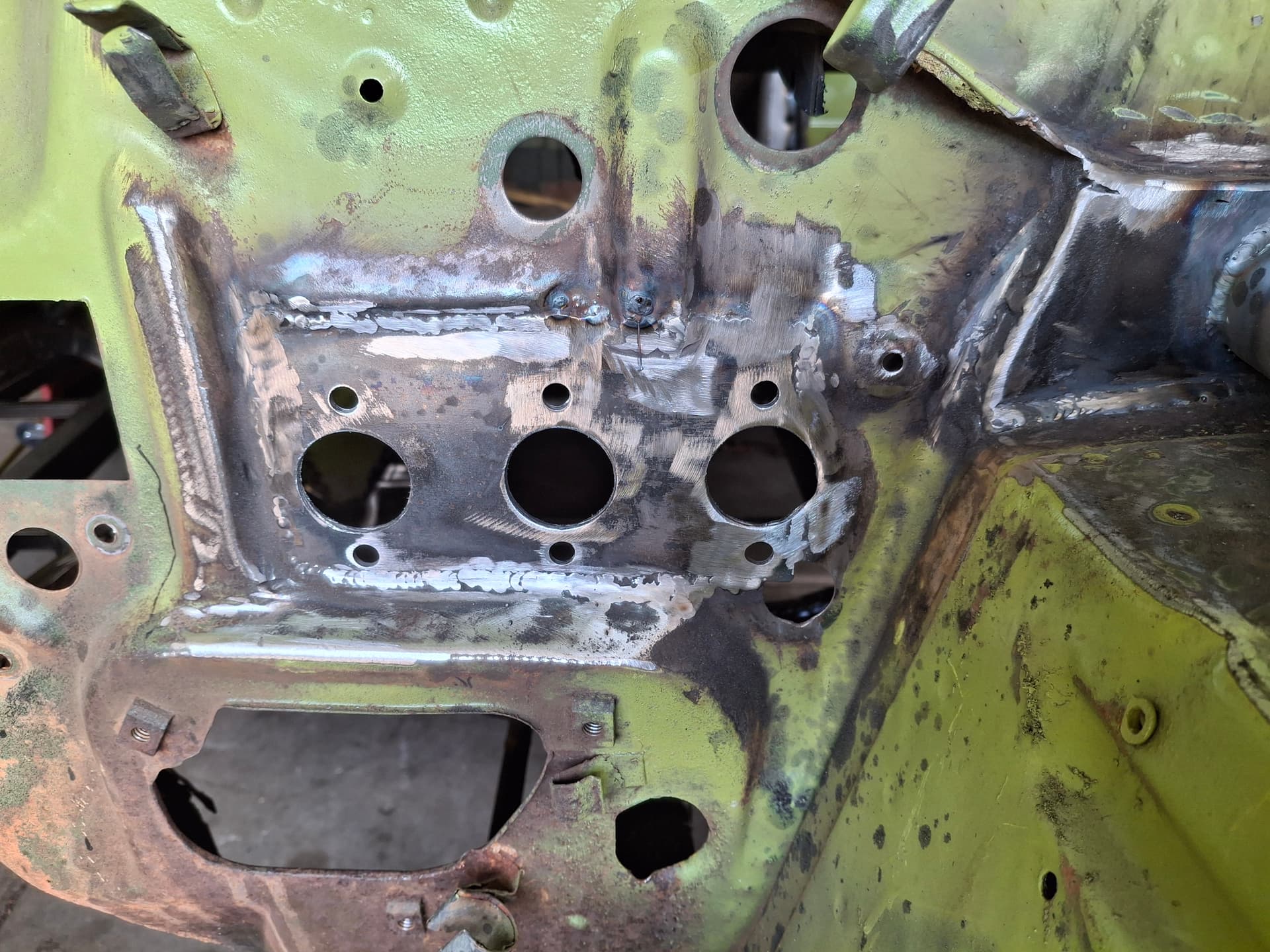
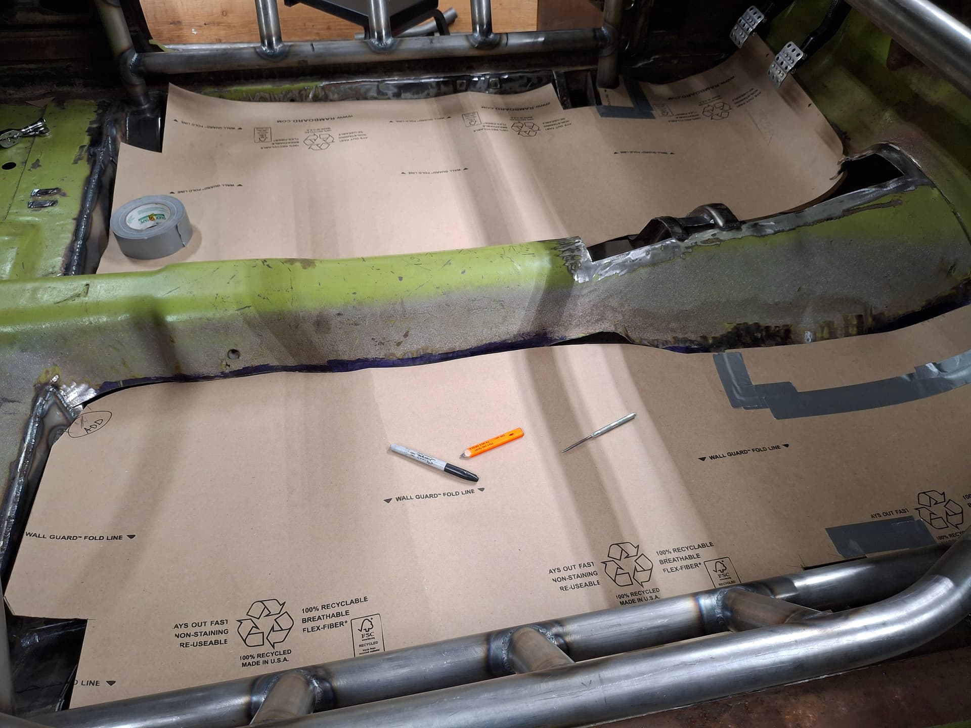
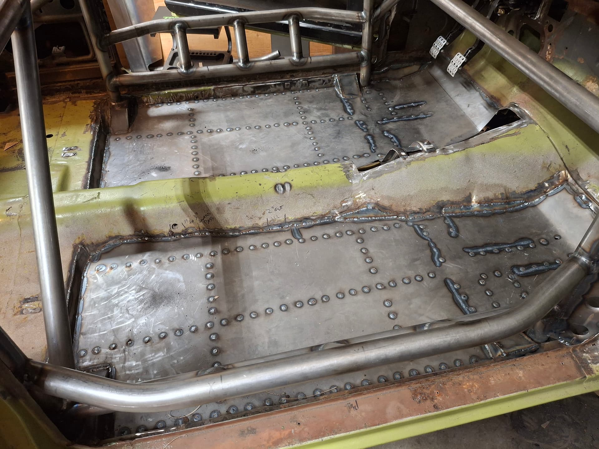
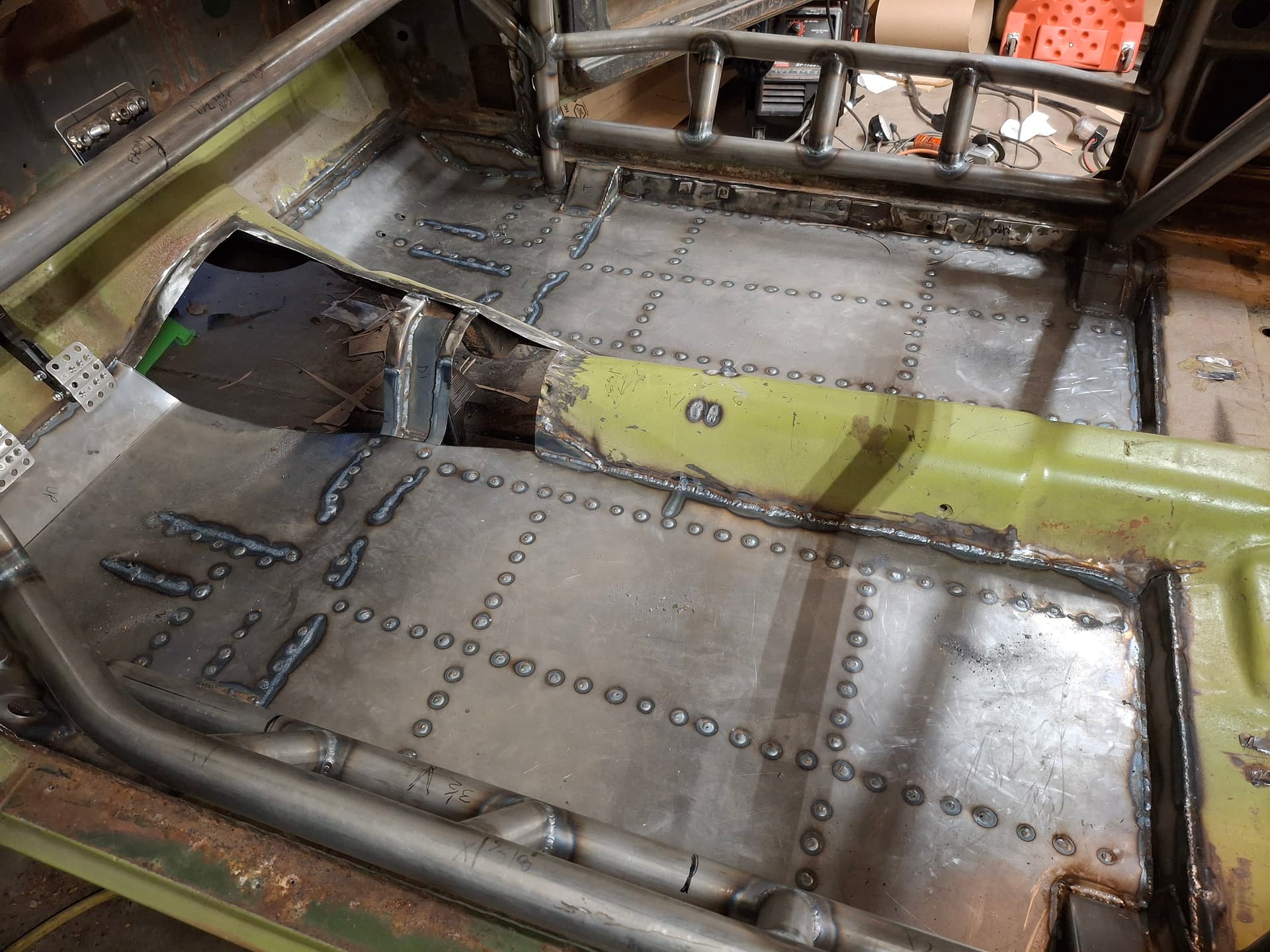
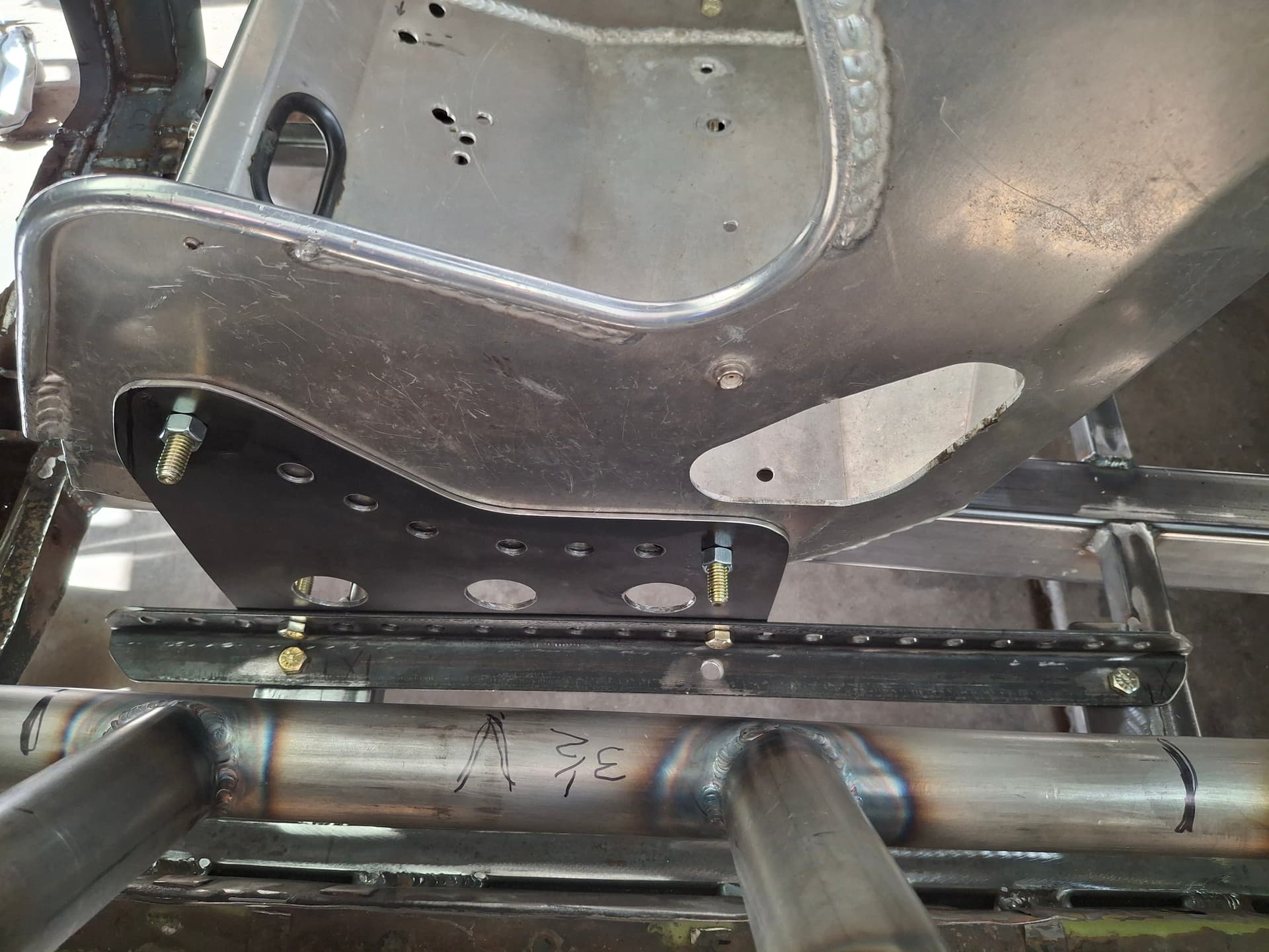
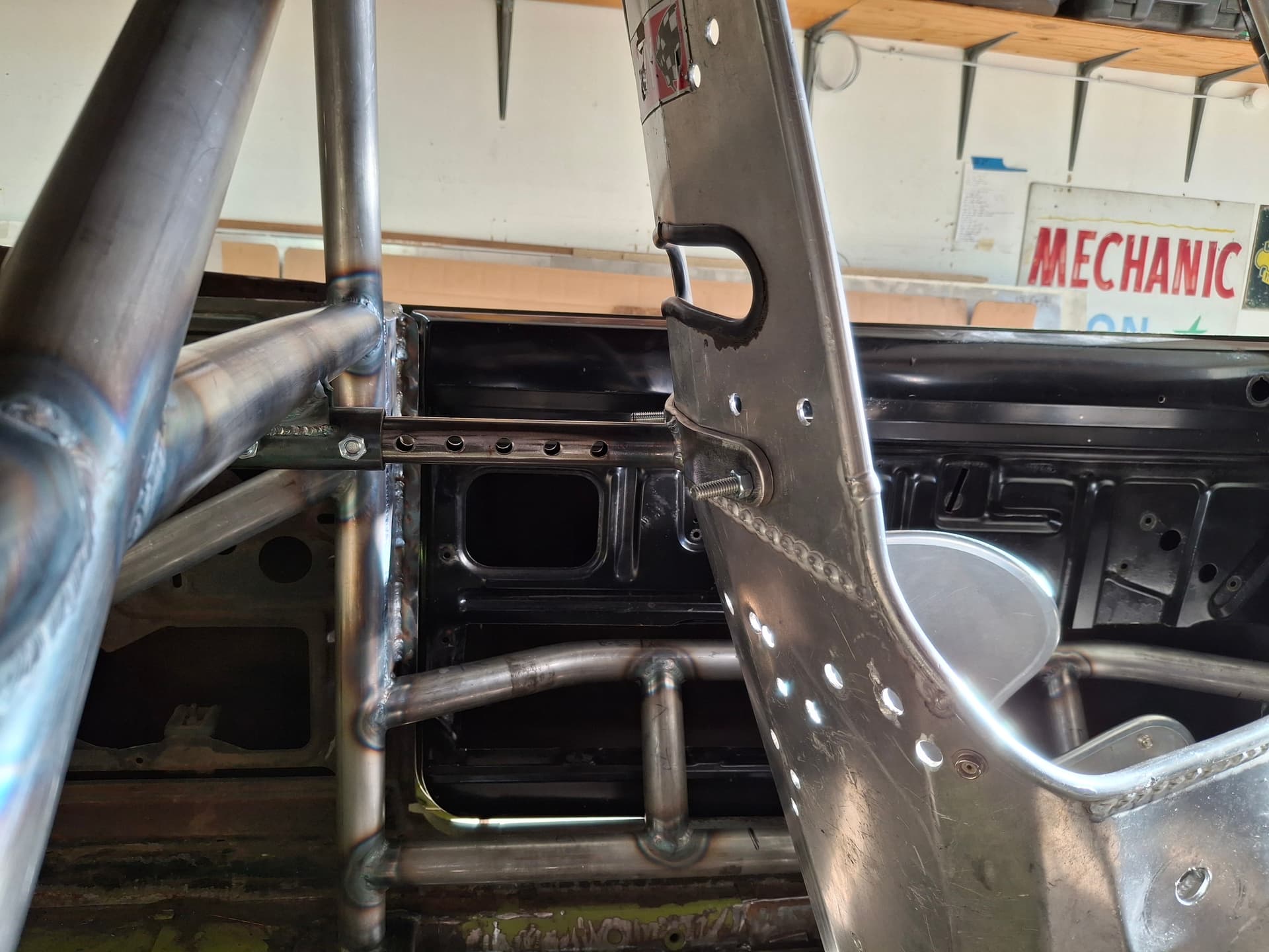
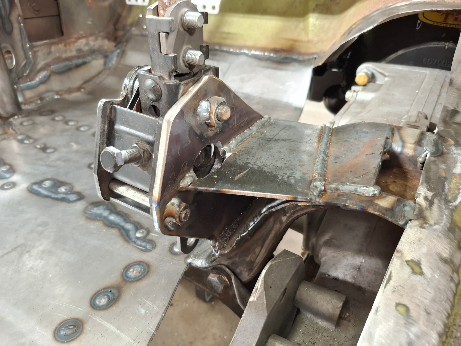
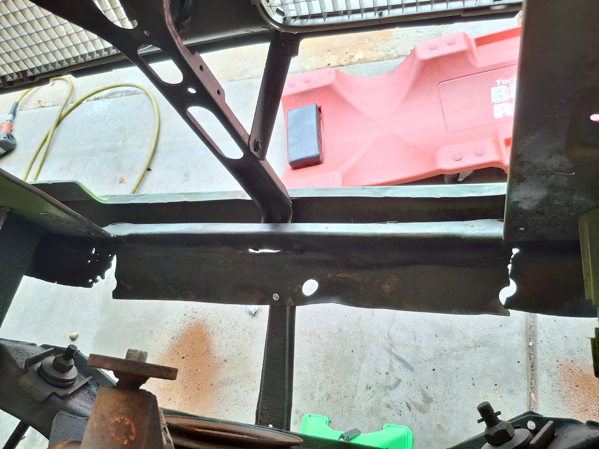
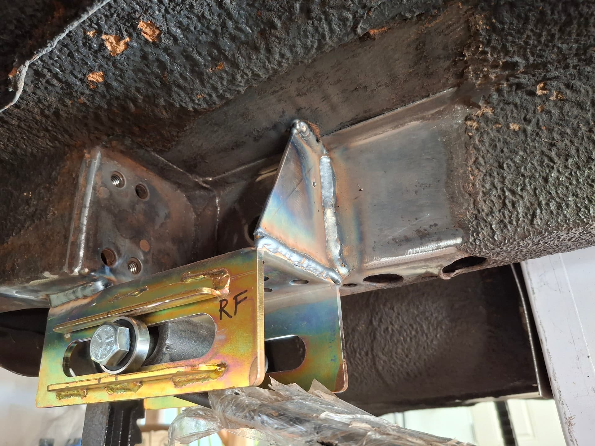
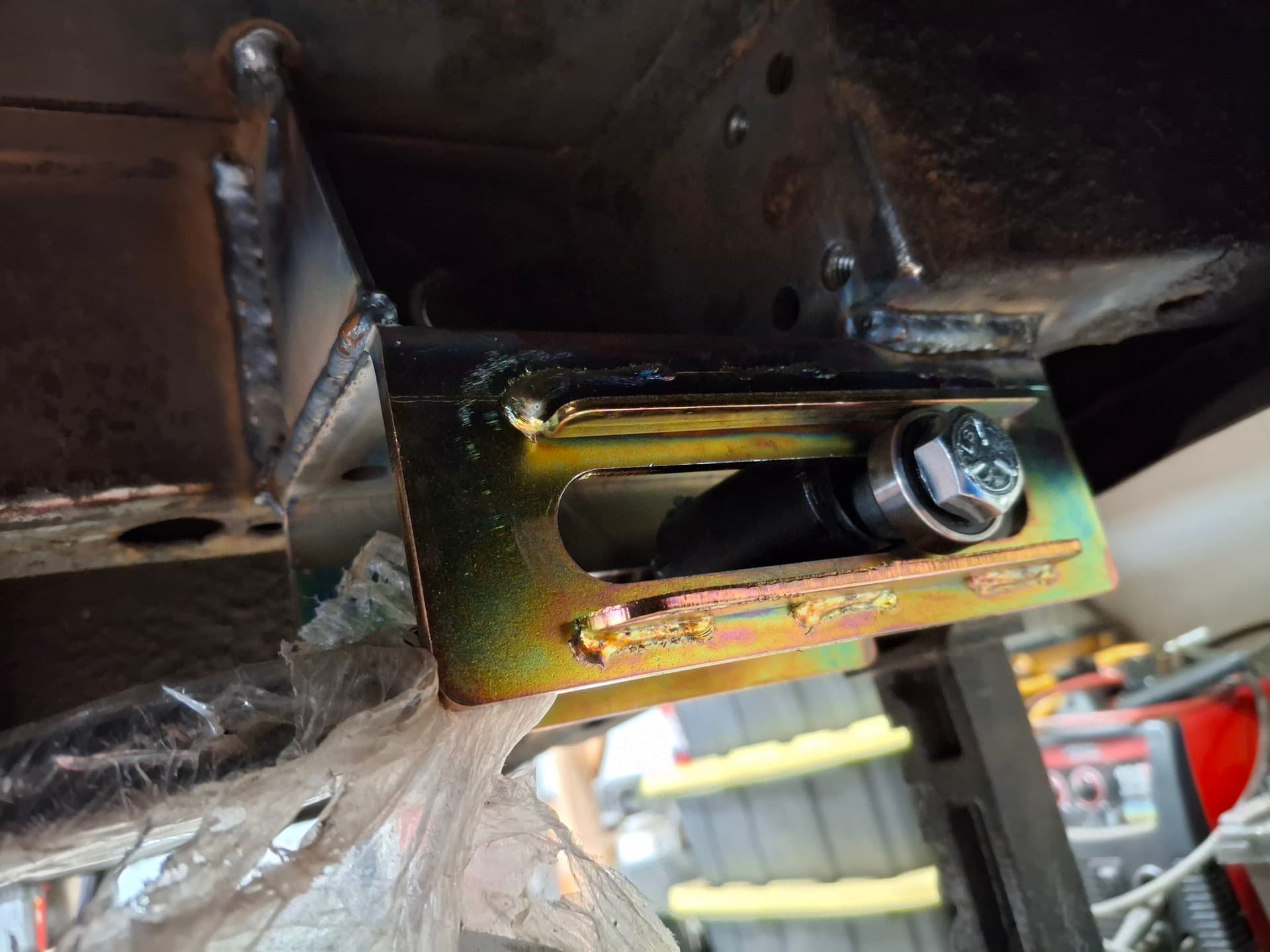
Today, I’m getting the car situated in my two-car suburban garage in Aurora, and I’ll begin stripping the rest of the interior, engine/transmission, and drive shaft. The first project will be to fabricate a rectangular tube subframe to connect the factory front and rear unibody frames and to provide outriggers on which the roll cage main and front hoops will land (versus relying on the floor pan). From there, I’ll start fabricating the cage.

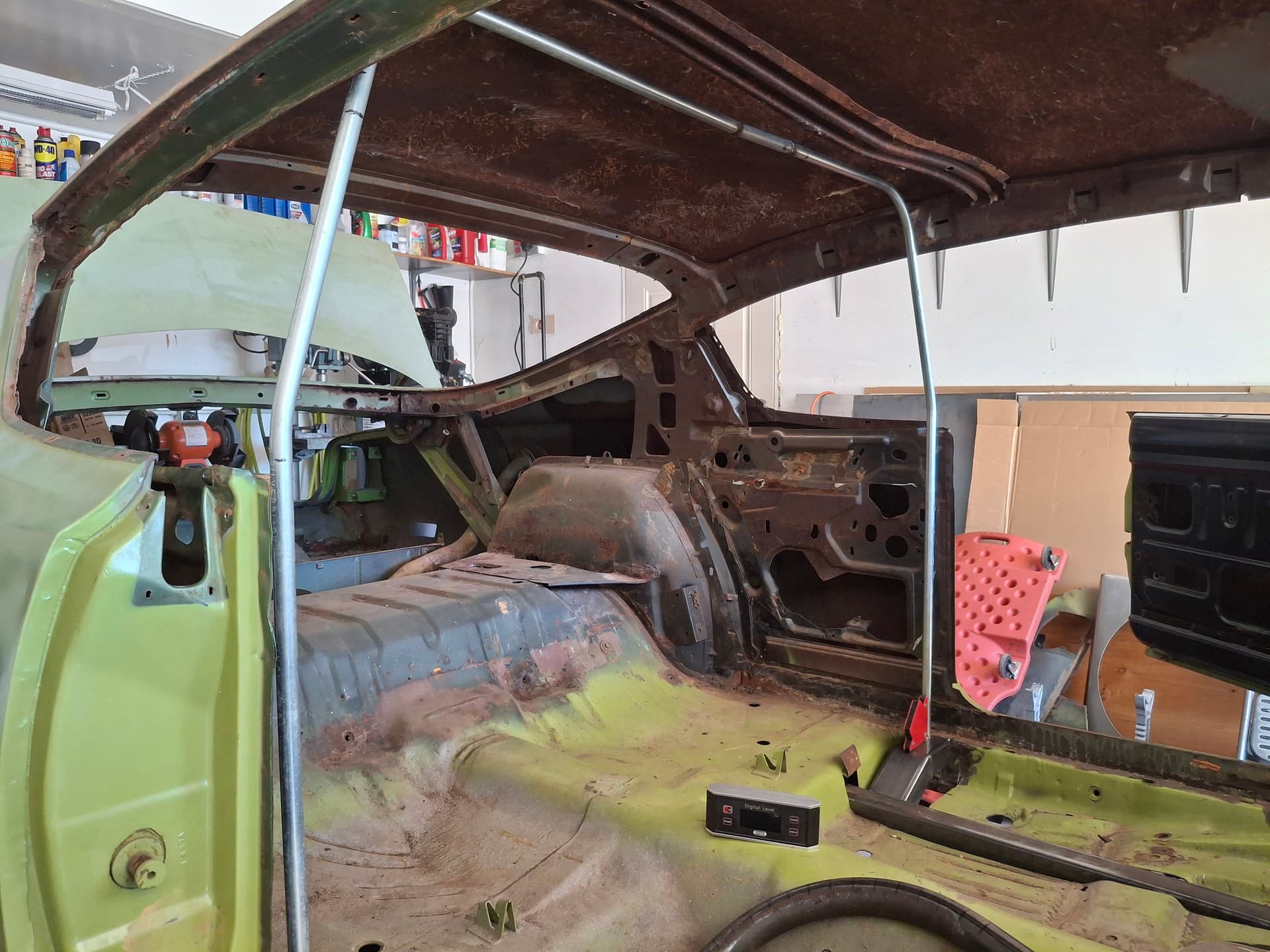
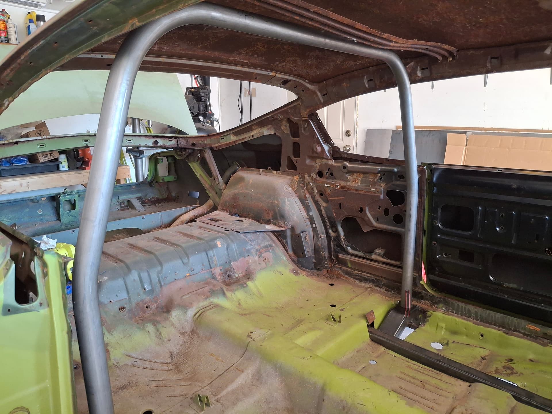
Until the next installment, here’s the car as I found it:


Hi Justin. Looking forward to “watching over your shoulder” as you document your build. I also do most of my own work. I’ve built many Detroit engines in the past but the Cosworth BDG in my race car is way over my head. Other than that I’ve rebuilt the chassis on my Bobsy, including all new skin on the monocoque, new header, new 4130 suspension arms, etc.
The club is very happy to you as a new member, especially as a “nuts and bolts kind of guy.”

Hey Justin. Love it! I’ve got my popcorn ready and will be watching your progress.

Thanks, Tom and Jon. Tom, beautiful car, and I hope to see it at one of the races soon.

The Barracuda is sitting in the garage, and I should have the garage cleaning finished this evening to where I can start digging into stripping everything.

1 Like

July 26 Update

With a couple nights and a good day’s work today, I have the car stripped and placed dead level up on jack stands. Even after cutting through the windshield rubber, I ended up having to put on a face shield and welding jacket and kicking the thing out from the inside in a shower of glass. :sweat_smile:

Thursday night, I even got a few hours of help from my ten-year-old niece who wanted to hang out and learn about mechanics. It was the first time she’s taken interest in working with me and ever worked with these types of tools, and she’s a quick learner and seemed to really enjoy the work. We might have a hotrodder and future RMVR member in the making.

Today, I designed and fabricated the right subframe and put a plan together for the roll-cage outriggers that will tie from the subframe into the rocker panels. The subframe connects the rear frame rail with the torsion-bar crossmember where the front frame rail dies in. Pay no attention to the rot holes and fiberglass hack-job patches peppered throughout the floor pan; I’ll be cutting out the driver and passenger pans to install a beaded flat pan I’ll fabricate to get rid of all the unnecessary factory seat contour business to clean and lighten things up a bit.

The left subframe should go in much quicker tomorrow now that I know the lay of the land.


Rear Frame Rail

Torsion-bar Crossmember and Front Frame Rail

I finished the subframe last night. I built outriggers" that tie the subframe to the rocker panels. The roll cage main and front hoop legs will land on and weld directly to these outriggers. I designed the outriggers in a way and only tack-welded them in place for a specific reason:

I can fabricate the cage very tight to the A-pillars and roof for both structural rigidity and more room, and I will only tack-weld the hoop legs to the outriggers. Then, I can fully weld the entire cage except for the very top welds that I can’t reach due to the roof/A-pillars. Once everything is welded, I’ll cut the leg tack-welds, cut the outrigger tack-welds, and drop the outriggers out of the bottom so I can drop the entire cage through the floor where I can then weld the top joints that were blocked. Then, it’s a matter of lifting the cage back into place, finish-welding the outriggers and the hoop legs, and finish welding the rear braces in the trunk.

If only fabricating the cage were as easy as typing this post. . . .


1 Like

Impressive fabrication skills Justin. Thanks for allowing us to follow along.

I’ve been creeping along with the cage and got the main hoop bent up and the rear brace plates fabricated. For bent cage pieces, I like to start with 1/2" electrical conduit (EMT) because it is easy to manipulate, easy to cut/weld, and provides a visual for me that other templates don’t (like card paper/board, plywood, etc.) Keep in mind that the EMT hand bender is a much tighter radius than the 1.75" tubing bender, but I take that into consideration when laying out things.

Something that took a lot of consideration was the angle of the main hoop where it bends in from vertical at the top of the door. I created a quick sketch below to show you what I mean. I struggled with form over function here since I’m of the philosophy that those factors in many components of a race car aren’t mutually exclusive. Both the “A” and “C” pillars are angled in 16° and align when viewed from the back/front of the car. At this “B” pillar situation, I found that to land the hoop leg on the chassis outrigger with enough room to weld around it while at the same time placing the roof radius within 1" of the roof rail, the angle from the top of the door to the roof was much straighter at 10° than the “A” and “C” pillar angles. After mocking up a piece of EMT with this angle, the car looked bizarre from the front and rear with the “A” and “C” pillars in line and the main hoop poking out of line. I mocked up a piece of EMT with a 16° angle to matched the “A” and “C” pillars, and the aesthetic was clean and natural. I decided to match the pillar angle, and I will return the front hoop inward to meet the main hoop where I can then gusset nicely into the roof rail for a rigid structure. I adjusted the height of the bend lower, bent up the main hoop using my trusty Speedway Motoring tubing bender (I say this facetiously because it’s a pain in the butt bender to use compared to a floor-mounted $2,000 bender), trimmed it into place, and tack-welded it.


Turning my attention to the rear diagonal braces, I confirmed what I expected but didn’t want. Ideally, I wanted the rear braces to land 8" from the very rear of the body just above the rear leaf spring perch. This structure would create strong triangulation where the rear would be less likely to flex. However, as I expected, this fastback is just too long to where the brace angle would be below the minimum 30° required by both the SCCA GCR and NHRA rulebook (in the event I ever want to take the car down the drag strip). A 30° brace lands closer to the center of the leaf spring, but it’s what I have to do. I cut out the factory bracing for the fastback fold-down second floor deck and sanded the metal clean.

The next consideration is the mounting plate. SCCA requires a 0.080" minimum plate of an unspecified width when welded to the floor, whereas NHRA requires 0.120" x 6" x 6" minimum, which I think is a far better spec, especially for a road course car. The issue with unibody cars is that the rear subframe is a “C” channel with an open top. The worker/machine rests this “C” channel against the bottom of the floor plan and spot welds approximately every 2" so that the floor pan completes the rectangular tube of the subframe. What most people do when securing a cage to the floor pan is slap a piece of plate down, weld the perimeter, and weld the cage tubing to the plate. For downward forces, this method works just fine, but the repeated upward forces as the body twists during normal use and the lateral forces in a wreck can cause issues. The center of the plate where the cage tubing is welded is not actually fastened to either the floor or subframe, so the plate can flex up and down. The flexing allows more chassis twist, and it weakens the plate and welds through work hardening. The other issue is that the perimeter welds secure the plate to the floor pan, but the entire system then relies on a few spot welds to hold the thin floor to the subframe. In a bad roll, it is far more likely for the floor pan spot welds to tear out and allow the cage to distort than it is for the plate to tear out of the floor.

To address both of these concerns (body/chassis flex, work hardening, and wreck protection), I placed the plates above the subframe where I will land the rear braces. I cut 0.120" x 6" x 7" plates and broke them to return up the floor pan for additional rigidity. I marked the subframe “C” channel welding flanges on the plates and drilled a series of rosette holes every 1" with a third row in the middle of the subframe. I also laid out the plate placement to where the fuel cell will land in between the plate. I welded the perimeter of the plates. Then, I used enough amps when welding the rosette welds to actually burn a hole through the floor pan skin to where I could rosette-weld the plate directly into the subframe “C” channel flange and then the floor pan. Fabricated in this way, the plate is a direct part of the subframe. It is impossible for the plate to flex up anywhere under normal use, and the cage tube is far more likely to tear off of the plate in a wreck than the floor and plate are to separate from the subframe.


I’ve been plugging away at the cage in the evenings and weekends and have made good progress. The plan of cutting all the tack welds and dropping the subframe outriggers and cage through the floor worked perfectly to where I had tons of room to weld all the top joints.

Common on these cars, the battery acid rotted out a portion of the inner fender and the subframe, so I cut out and replaced that section. I also reinforced the passenger side subframe with 1/8" plate where the roll cage lands. I gusseted the firewall with 1/8" plate where the tubes pass through, and I gusseted the tubes to the inner fender/shock tower with 1/16" plate for greater rigidity. I fabricated a removable 1.5" diameter crossbar to tie together the top of the front structure for greater rigidity and side/corner-impact protection for the engine.

The last parts of the cage are the horizontal seat/harness bar on the main hoop, the door bars, gussets tying the main and front hoops to the “A” and “B” pillars, and some taco gussets at the rear brace “X” and the “T” intersections where the engine compartment bar ties into the front hoop.


Roll Cage Fabrication
Aside from welding a few joints and fabricating some gussets, the roll cage is complete! I mocked up the seat and steering shaft/wheel to located the height of the seat and dashboard and main hoop safety harness crossmembers. I have the crossmembers tacked in place for now just in case I need to move them, but I think my seat mockup is accurate. I’ll weld those after I finalize the steering, pedals, and seat situation.


Floor Support Fabrication and Torsion-Bar Crossmember Repair
I also finished fortifying the sheet metal kick-up into what used to be the rear seat and fabricated a 1" x 1" tubing floor subframe to support the seat and safety harness. While I saw some issues from under the car when I first looked at it during purchase, I got a good look at serious issues with the car in the air and after removing the floor pan. Some nimrod decided it would be a good idea to torch critical support areas of the torsion-bar crossmember in order to fit aftermarket shifter linkage rather than getting the correct shifter mounting bracket and linkage. I cleaned up the torch cuts, fabricated pieces, and rebuilt the crossmember. While I was in there, I added gusset plates to the torsion bar sockets to resist twisting since I’m using huge torsion parts compared to factory, and I boxed the left side of the crossmember to further support this section that was compromised and now has multiple weld joints versus a single stamped crossmember.


Front Subframe Repair
Another issue that I suspected was major rot in the left front subframe. When I first inspected the car during purchase, I noticed someone had used sheet-metal screws to fasten a huge piece of strut channel (as in for electrical/HVAC) to the underside of the subframe. I suspected rot or floor-jack damage, and I was correct with the bottom of the subframe being rotted out from the torsion-bar crossmember up to within inches of the upper control arm. I cut out all the rot, cleaned up and primed the inside of the subframe channel as best I could, patched the sides and bottom, and welded up the screw holes.


Upcoming Work (Steering and Pedals)
I’ll be turning my attention to fabricating an adjustable steering shaft mount and installing the brake and clutch pedals. Unfortunately, the factory swing-pedal assembly isn’t going to work. I have no idea how anyone could drive the car from the factory because the clutch and brake pedals are 11" off the factory floor, and the factory throttle pedal is 6" below the brake pedal when the brake is fully compressed–no heel-toe action happening there. I’d have to cut and reposition the pedal levers along with some other modifications to make the ratios come out.

Another consideration is that I am going to use a hydraulic throw-out bearing due to header clearance issues and was planning on converting the clutch pedal to a master cylinder. However, all the throw-out bearings use a 3/4" master cylinder, and I can’t find a period master cylinder that small. While I was trying to stay factory/period, I’m going to give in on this part and install a Wilwood clutch/brake swing pedal combo assembly with a balance bar and three AFCO rectangular master cylinders–a 3/4" for the clutch and likely a 1" for the rear brakes and a 1" for the front brakes. I might go with a 7/8" for the fronts with their large 2.75" caliper pistons, but I think a 1" might be a better feel for track use. The pedal assembly both moves the clutch pedal to the left for better leg ergonomics, and the levers are adjustable from 5.25:1 to 6.1:1 ratio to fine tune things. Other benefits are that the front and rear brakes will be on their own circuits with more fluid, and I won’t need to plumb in a proportioning valve since I can adjust at the balance bar. I went with AFCO aluminum master cylinders that fit the Wilwood bolt pattern because after I sand off the cast logo and paint them, they could be mistaken for older cast iron units.

I turned my attention to the fuel cell to take a break from the cage. When considering fuel cells, I wanted something narrow front to back to keep the weight as far forward as possible, and I also wanted something that either already has or can be easily made to have a sending unit since the car will see street use for promoting RMVR at cruises/cars and coffees to where I’d like a fuel gauge. I settled on a 15-gallon RCI cell marketed to off-roaders, and after months of patient searching found a new one locally on Facebook Marketplace for $120, less than half the price of retail. It has a swing-float sending unit, so I’ll replace that with a vertical sealed sending unit so I can pack the cell with foam.

To prep the trunk, I welded in a crossmember where the rear braces tie into the subframe for both side protection of the cage and to stiffen the chassis since the car has no rear crossmembers and only a very mildly reinforced pan section where the shocks attach to the body. I placed the fuel cell as far forward as possible without interfering with the cage and rear axle components and as low as possible but still above the rear axle for protection.

After I drew out the cut lines, I realized that about 2/3 of the spare-tire well will remain, which influenced my design. The spare-tire well will be a great place to house the electric pump, its 100-micron pre-filter, the pressure regulator, and the post-pump 40-micron filter where I can cap it with an aluminum lid to isolate all those components. I won’t have to worry about spilling fuel during filter maintenance since the well has a hole in the bottom where I can place a drip pan, and I won’t have to worry about messing with the filters in a hot engine compartment if I have a clog issue. The downside is that part of the spare-tire floor was rotted out, so I had to patch that.

Fabricating a rear firewall to isolate the trunk from the driver’s compartment would be cumbersome with this fastback design and add substantial weight for the brackets needed to properly seal the perimeter, so I designed an 18-gauge “firewall” housing into which the fuel cell sets and bolts. I will cap the well with an aluminum lid siliconed and bolted down, thus isolating the cell from the driver’s compartment. I’ll fabricate a sealed access door to get to the filler neck. I made the housing walls above the fuel cell tall enough for 90-degree AN fittings to clear so I can take the fuel supply, return, and vent lines out and down into the spare-tire compartment. I don’t have a box-and-pan break, so breaking the sheet metal on a workbench with angle iron, clamps, a mallet, and a body hammer turned what would be a couple hour’s of work with a break into an all-day task, but I think it turned out nice. However, fabricating it this way tied everything into the subframe and roll-cage for even more stiffening between the axle and rear spring perches.

The fuel-cell “firewall” housing (still need to weld on the lid nuts and clean up the spare-tire patch welds)

A shot of the rear roll-cage crossmember with the fuel-cell housing tied into it for further triangulation

The underside. Note that I still need to trim the well wall at the spare-tire. Also, the rear axle is hanging in the photo, but I checked clearance with the axle loaded.

The fuel-cell installed and a diagram explaining my plan for the equipment down in the spare-tire well.

This evening, I laid down the last weld of the roll cage! It was certainly an involved part of the build–likely what will be the most involved–but I had a lot of fun. Now I have a good foundation to begin focusing on the driveshaft safety loop, floor pan, and transmission tunnel.

Notice my OH SH*T! bar on the roof crossmembers? Lol, that’s actually a handle for getting in and out of the seat. I may weld on a hook for the steering wheel but am going to wait until the seat is in place.

After an exiting RAKC to fuel the fire, I’m back to plugging away at the Barracuda and updating this thread. Some of these photos are out of chronological order, but I fabricated the steering-shaft mount at the dashboard crossmember, the firewall mount for the master cylinders, and brake/clutch pedal assembly. I also fabricated the drive-shaft loop crossmember.

I designed the steering-shaft mount so I can adjust it side to side 1/2" and with 1-1/2" of vertical adjustment with the adjustment both ways landing in the middle where my mock-up thinks it will be permanently.


Mocking up the pedal assembly

I cut out a section of firewall and welded in a 1/8" plate to mount the two brake masters and the one clutch master

The pedal assembly installed (I still need to fabricate the vertical support brackets)

The drive-shaft loop

I finished the brake pedal assembly supports and the steering shaft. For the shaft, I used 3/4" x 0.120" DOM and converted the bottom to DD for the steering-box u-joint for ease of removal. The firewall gets an aluminum plate with a bearing.

I haven’t posted in a while and wanted to catch up. This installment includes

Floor Pan
Driver’s Seat
Shifter Mount
Shifter Linkage
Transmission Tunnel cover

Floors
More spot weld holes I had to drill than I want to remember. I continuous-welded the floor and torsion-bar crossmember from underneath.

Driver’s Seat
I fabricated an adjustable mount system for the driver’s seat that mounts to plates welded into the subframe.

Shifter:
The Hurst Competition Plus shifter arms run directly into the back of the torsion bar crossmember with no way to route linkage without binding. I relocated the shifter from the transmission tail housing to above the crossmember. I’m running solid motor mounts (rubber transmission), so there shouldn’t be an issue with flexing of the linkage in comparison to engine twist seen with rubber mounts. I also took a 10" straight shifter stick I had, cut it to place it where I need, and welded it back up.

Shifter Linkage:
I built linkage using 1/2" tubing with heim joints on the transmission side and the Hurst swivel joints on the shifter side. The linkage turned out great and robust, although the revers 90° took some doing.

Transmission Tunnel
I fabricated the remainder of the transmission tunnel and removable cover to access the shifter and linkage for easy adjustment.

I finished what is the last of the chassis reinforcement, which was a front crossmember underneath the radiator. The A-bodies are susceptible to flexing in front of the “K” member due to a light/weak radiator core support. I cut out the bottom of the core support and bent up a piece of 1.75" cage material and welded it to the frame rails, followed by a gusset to tie in the vertical center grille and hood support. Coupled with the front cage legs and upper horizontal tie-bar, the front end should be pretty rigid.

Somewhere in the mix, I didn’t post photos of the dashboard build. The original dashboard was heavily rotted out along the bottom, and it wouldn’t work well with the cage front hoop and crossmember anyway. I decided to try and fabricate a new one with some 1960’s styling from aluminum sheet, which ended up being quite the project since I don’t have any brake let alone a brake long enough to handle the 53" piece. After building a mockup from heavy card paper, I spent the good part of a day at the workbench with angle iron, bars, clamps, mallets, hammers, and my body coxing and beating the thing into place. I have a little metal finishing to do to smooth out some bumps, but I’m happy with how it turned out. I started playing around with gauge placement but have decided to redo that configuration since I’ve decided not to run a speedo and am going to get a smaller tach.

Rear Suspension
We’re now getting into the mechanics of the Barracuda. I dug into the rear suspension, tearing out the brutalized factory leaf springs and small-V8 7-1/4" rear end with a tiny 5 on 4" bolt pattern, which I’m replacing with a stronger unit since the 7-1/4" are known to dynamite under race conditions behind the kind of engine I’m building. The new 1" lowered and progressive 130 lb. leaf springs came in from St. Louis Springs courtesy Peter Bergman Autocraft who is a Mopar racing specialty supplier and manufacturer, so I turned my attention to the spring mounts.

Leaf Spring Relocation
These A body cars are prone to the inner sidewall rubbing on the spring during cornering, but the springs can be moved in only 1/2" before they hit the frame rail.

Here are the factory configurations:

Rear Spring Shackle
Since I was already going to do modifications to move the spring in, I decided to ditch the rear shackle design in favor of a slider configuration. I bought the sliders from Speedway Motors, which are popular amongst stockcar racers. Rather than the shackle and leaf spring going through an arc as the spring flattens and arches, the spring’s bolt rides horizontally in ball bearings in a track, removing the vertical movement and associated twisting of the shackle and spring.

After mocking up everything with the car’s weight resting on the springs, I welded in the sliders in a way that both moved the spring in 1/2" and raised it (thus lowering the car) 1/2" from the factory setup. I fabricated a gusset to support the front of the slider.

Front Spring Hanger
The factory hanger uses 3/8" studs to secure it to a plate on the rear subframe. You must slide the hanger over the leaf spring eye and secure it in place with a 5/8" bolt and nut prior to lifting it up into position. The bolt head takes up the 1/2" gap between the bracket and frame rail, so that’s an issue for moving the bracket. To address this issue, I order alloy 5/8" bolts with tapered flat heads that use a female hex. I pressed out the mounting studs, welded up the holes, and drilled new holes to move the hanger in 1/2". Three of the holes will get grade 8 3/8" bolts, and the one lower hole with tight clearance will use an alloy 3/8" socket-head bolt.

I then welded extensions onto the hanger side and drilled a new leaf spring bolt hole 1-1/2" higher than the factory location (thus lowering the car), which is the measurement aftermarket lowering hangers use and about as high as you can move the leaf spring before it hits something. I countersunk both the factory and lowering holes where the new 5/8" flat-head bolt will reside, allowing me to cram the bracket right up against the frame rail to gain that 1/2" of tire clearance.

While I’m not certain they are necessary, I built some backing plates out of 1/8" plate to spread the load over the factory mounting plate, although it is already about 3/16" thick.

I’m waiting on the 5/8" flathead bolts to arrive before I can start mocking up the rear end to set pinion angle and weld on the new spring perches, so the next item is to prep the new rear end that I plucked from a salvage yard, including cutting off its spring perches.

Upper Control Arm Supports
I knew that there was some rust rot in the area of the upper control arm mounting points on the left side due to caked mud building up in the poorly designed bracket pockets.

I was surprised by how flimsy the factory fore and aft ears were since I was able to hold them with one hand and flex them. I suspect that under hard cornering, these may be potential areas for deflection and possible subsequent change to caster and metal work hardening, although the inner ears are well supported with a substantial bracket. I’d rather not remain wondering, though.

Along with my concern about design rigidity, there was significant pitting in areas and rot through in others, so I cut out the rotted areas and patched, reinforce the pitted areas, and built stiffening uprights from 1/8" plate. I also continuous welded the the inner bracket/shock plate to the inner fender where the gap allowed and into the roll cage horizontal at the top. I’ll patch the inner fender rot still show in the background from the inside next time I have the mockup engine out.

Lastly, both sides of the factory control arm mounting holes are reinforced with welded plates with ears that locate the factory caster/camber adjuster washers and lock them in place from moving in/out. Three of these ears were rotted away (two on the same plate), so I built them back up with welds and used a die grinder to shape them.

Left Side Original Design and Rust Damage

Left Side Repaired Rust and Reinforced

Right Side Original Design

Right Side Reinforced