Wow! Simply amazing Justin. Thanks for posting your progress. I’ll be sure to monitor this thread for any new developments. ![]()
1 Like
Very impressive fab skills, Justin. I am following as I have a '69 Barracuda convertible street car. Hope your project continues smoothly for you.
Mark Robinson
1 Like
Thanks @jonUU and @Datsun78. Mark, I didn’t know you were Mopar inclined as well. Hopefully you bring the Barracuda to a gathering at some point.
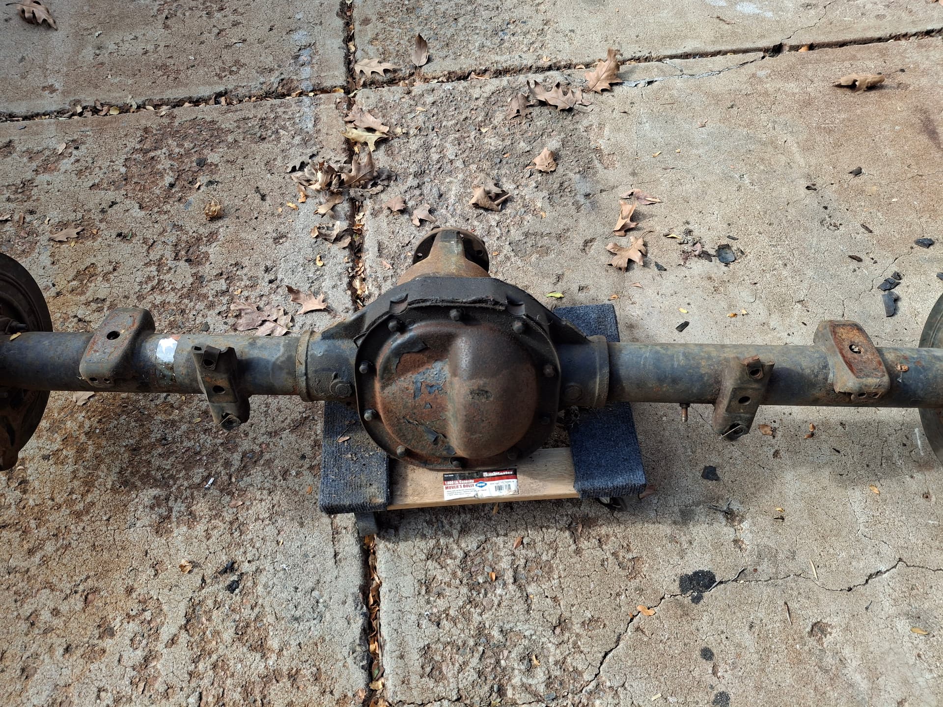
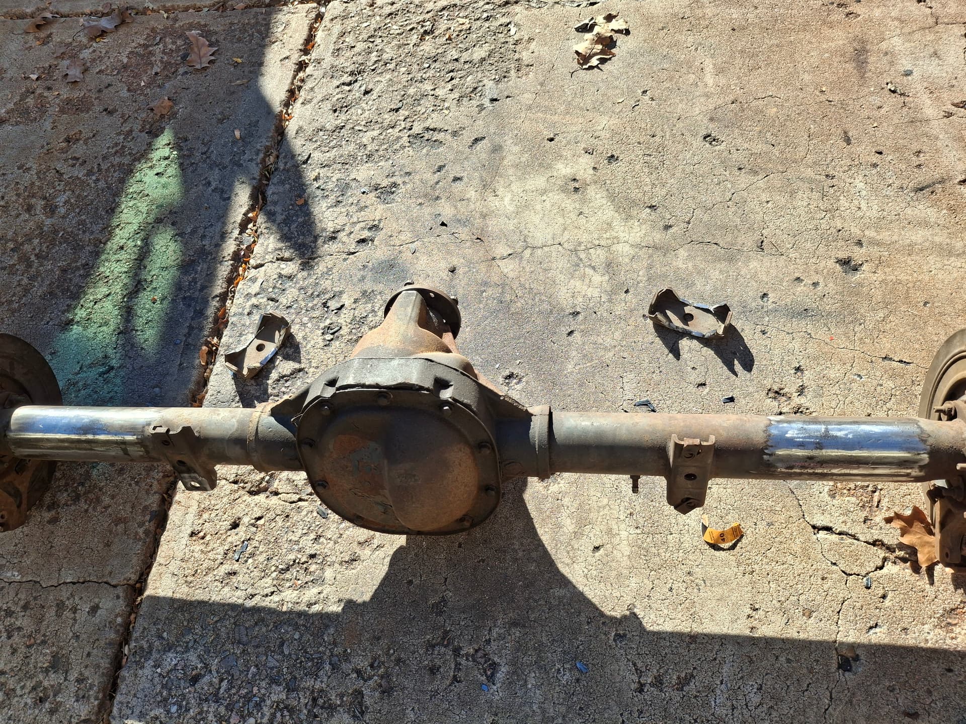
I cut off the leaf-spring perches from the salvage-yard rear end and prepped it for welding.
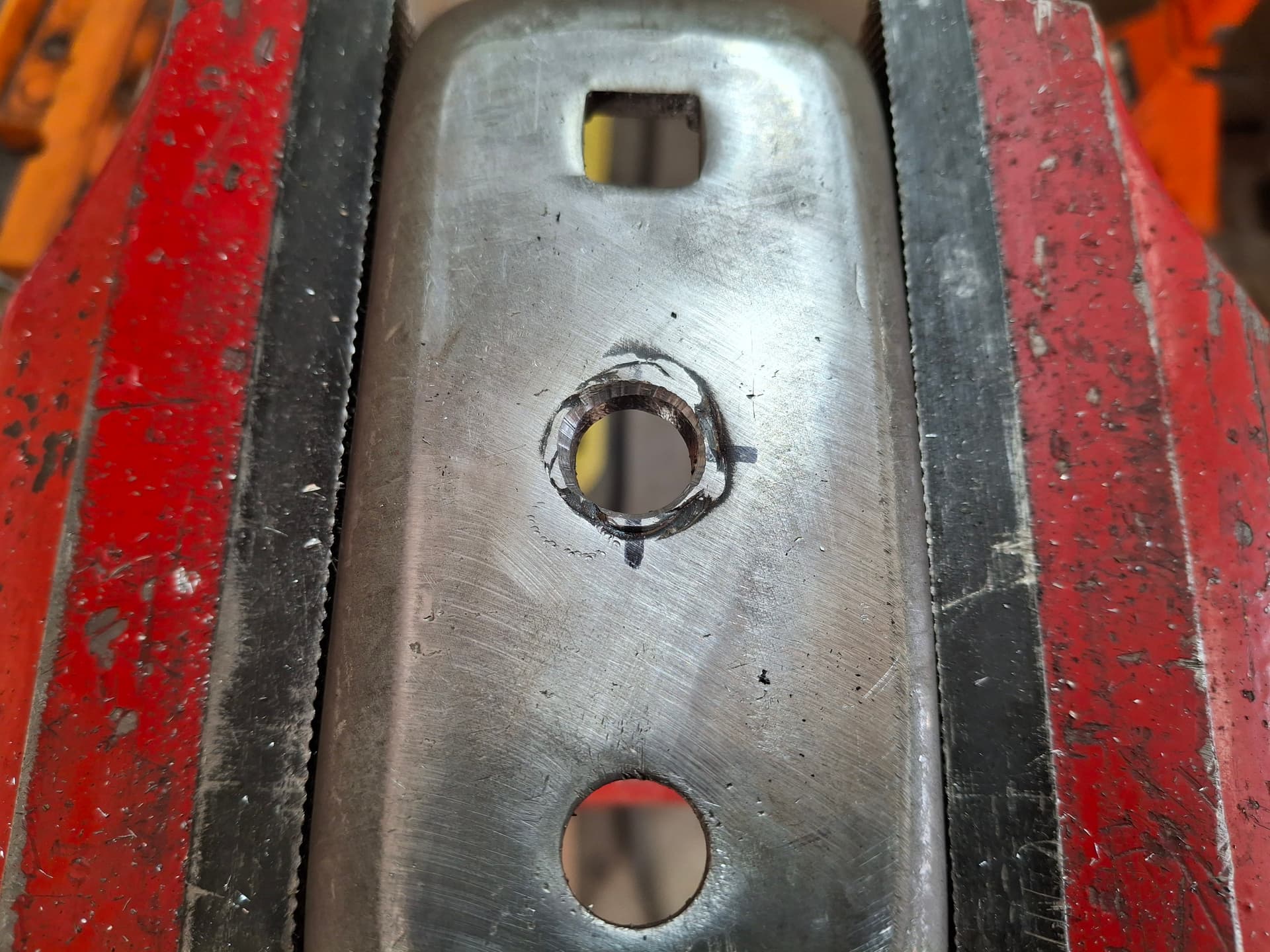
The new Mopar Performance spring perches, go figure, had too large a hole for the leaf-spring bolt, so I had to partially weld those up and drill the correct-diameter hole.
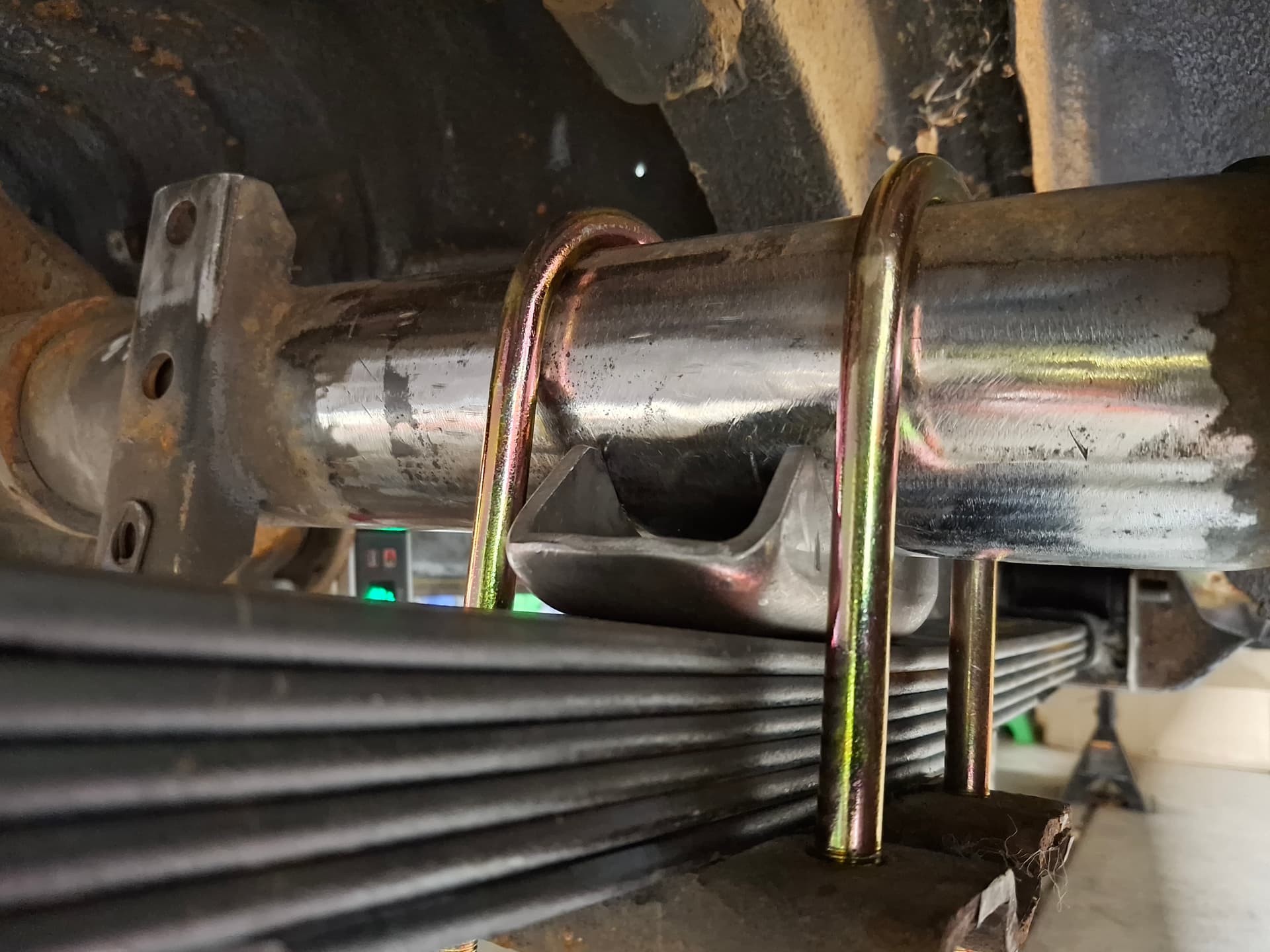
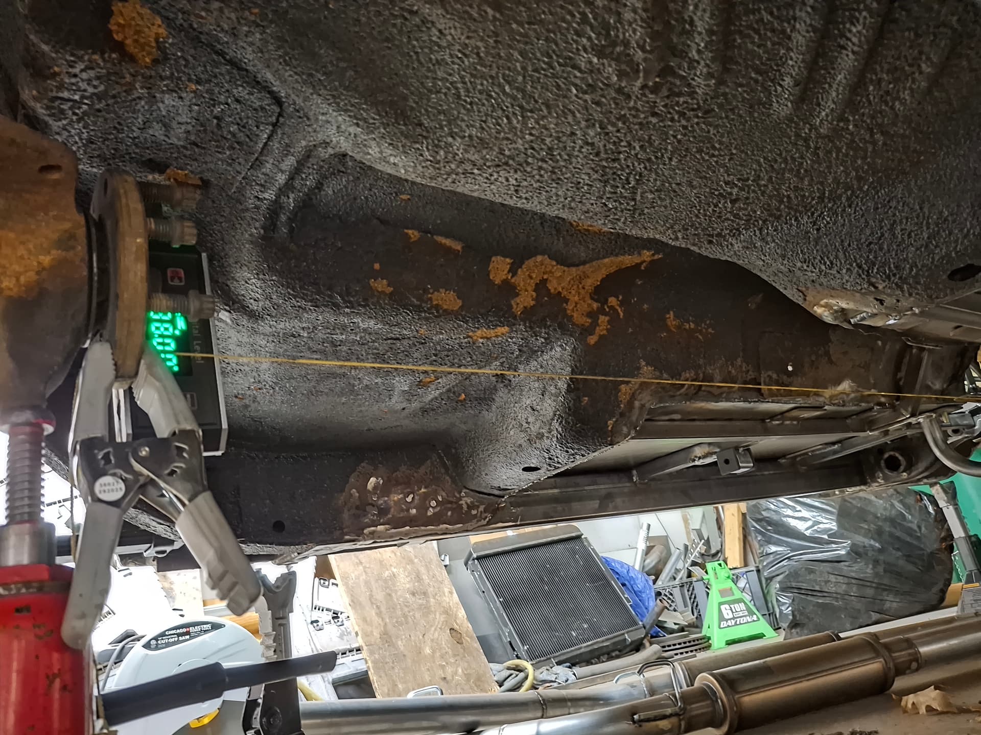
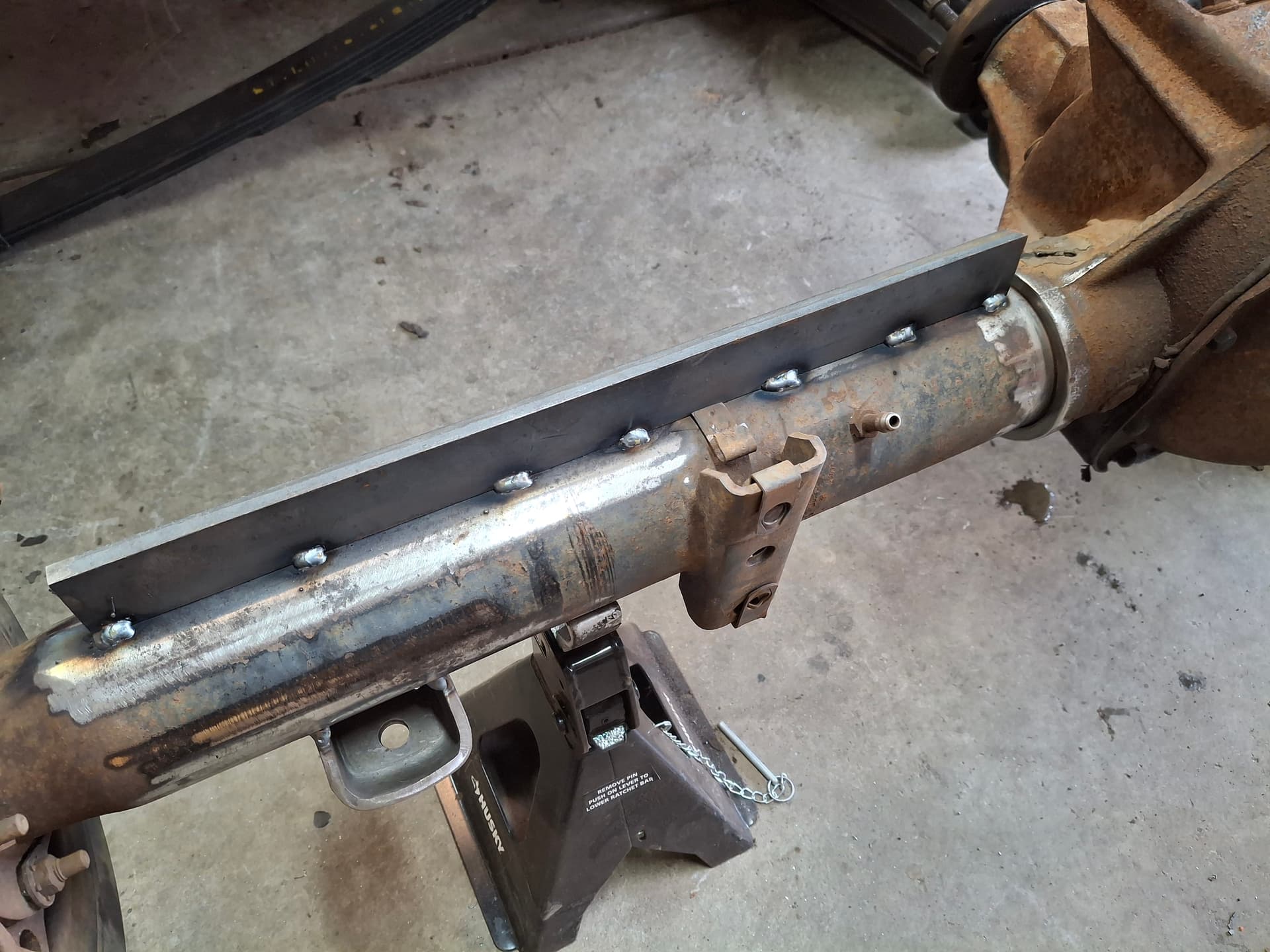
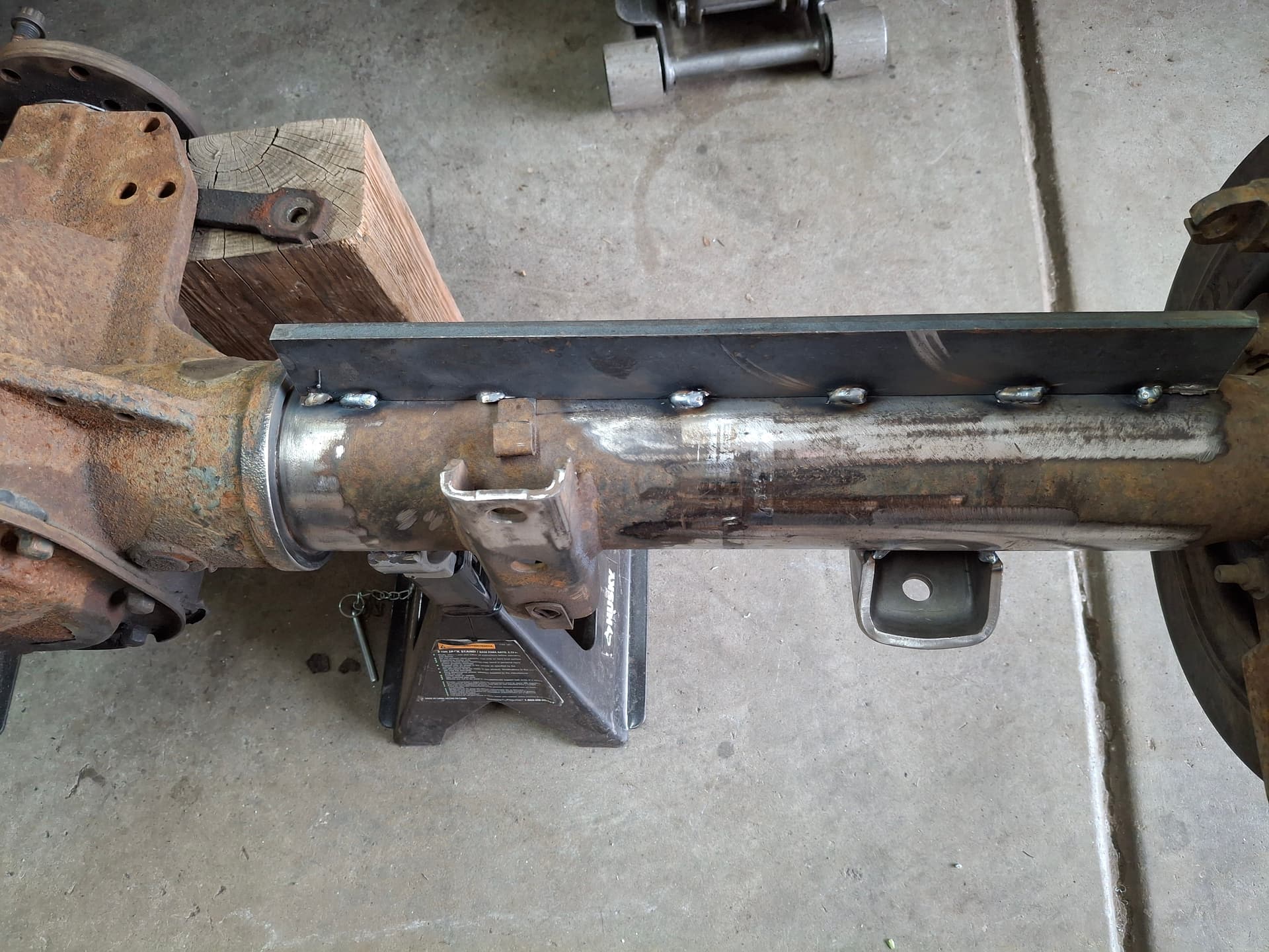
I mocked up the rear end in the car, checked wheelbase and center, threw weights in the trunk to mimic fuel and weights in the driver’s seat to mimic me, loaded the springs with the car’s weight, and set pinion angle. It ended up being 2° negative (pinion nose up) to get the slope and math to square with the transmission output shaft slope and front u-joint operating angle after baking in estimated axle wrap. After tack-welding the perches, I removed the axle for welding.
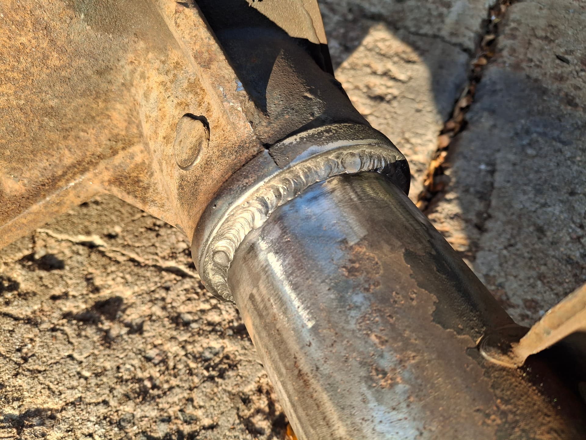
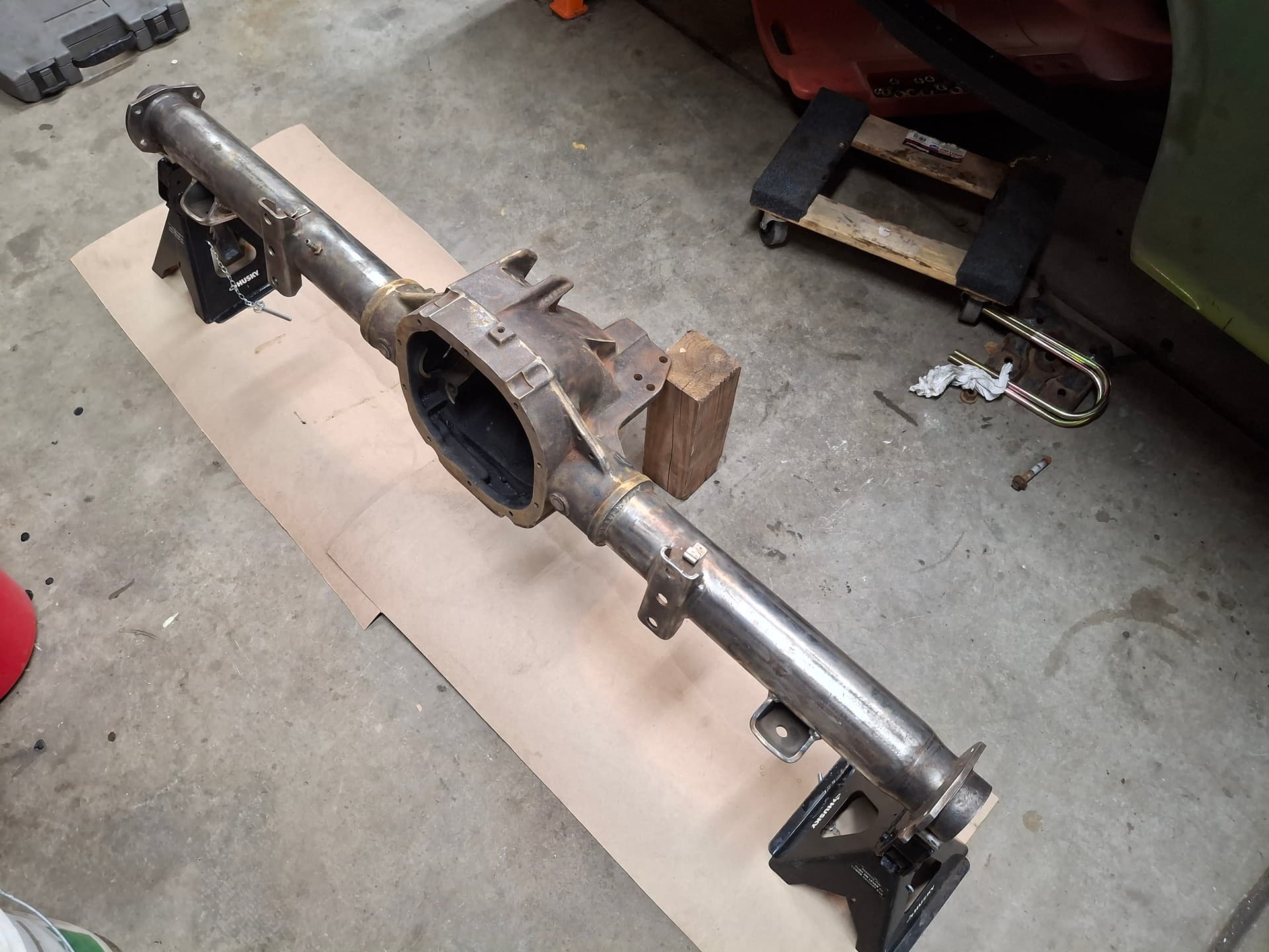
I don’t have an axle jig and am not interested in making one, so I tack-welded 1/4" strong-backs to the top of the housing. A weakness with these rear ends is that the steel tubes are spot-welded into the cast-iron center sections to where under race conditions the spot welds can crack and allow the center section to rotate. While I hate welding steel to cast iron since I don’t have a proper kiln for pre- and post-heating (and even with that steel and cast don’t always play nicely), I decided to roll the dice and weld the tubes to the center section since the car won’t be doing launches and the welds likely won’t crack. I preheated the weld areas with a torch and went to town. After welding, I wrapped the housing in a fiberglass blanket followed by a bunch of junk cloth blankets to where I had a burrito to help it cool slowly, which took a couple hours. Once cool, the housing showed no signs of warping when I cut off the strong backs and pulled measurements, so I’m happy.
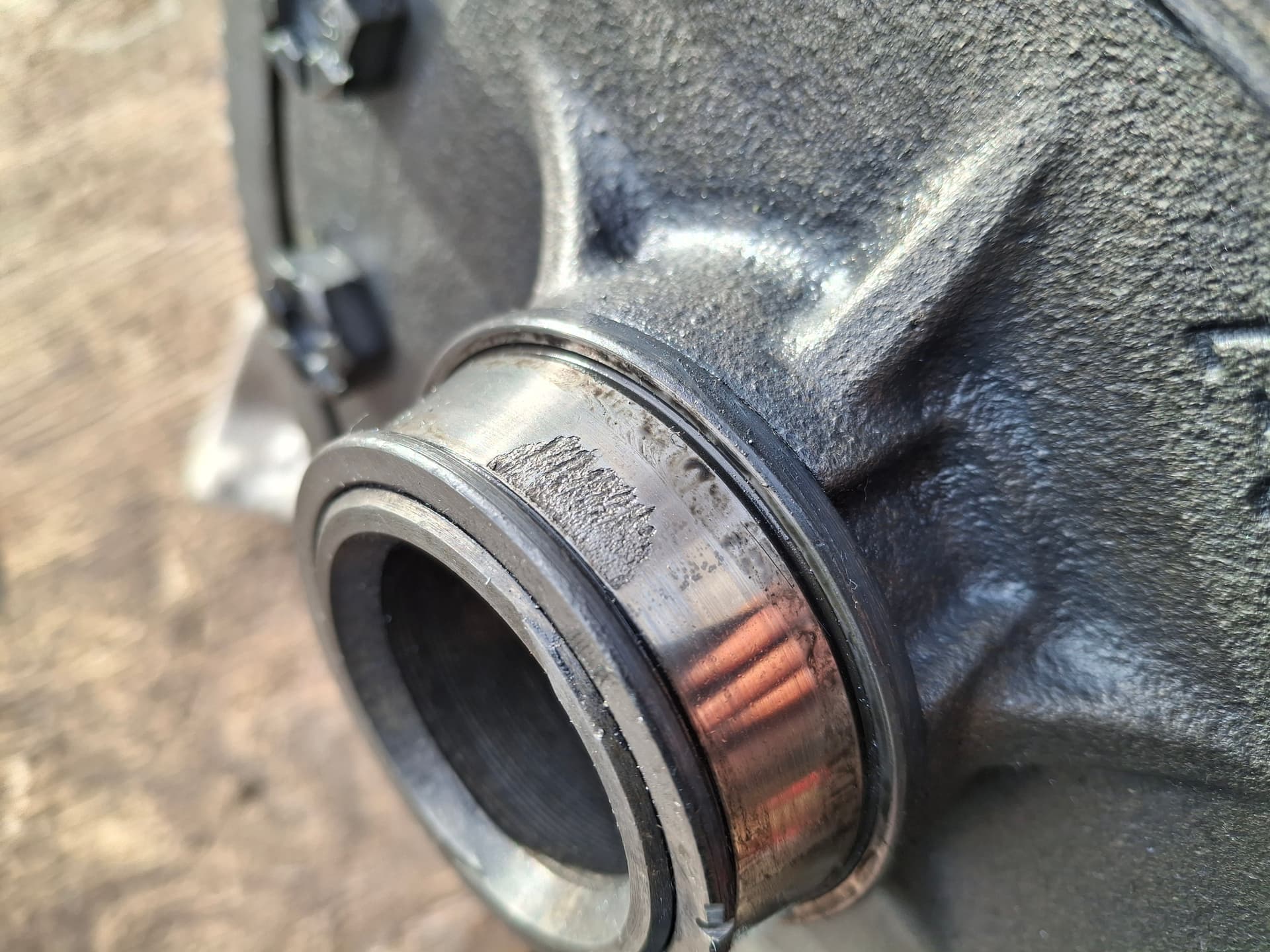
Unfortunately, I ran into an issue when I pulled the pinion seal to replace it since I was hoping the rear end would be good to run as-is with only seals replaced. While I had the pinion seal out, I pulled the outer pinion tapered-roller bearing to inspect it, and I didn’t like how the roller plating looked. It wasn’t flaking, but it looked worn to where it likely would soon. In order to replace the outer pinion bearing, I had to remove the differential to drive out the race. After dropping the differential, I inspected the carrier bearings and didn’t like how one felt when spinning it. Down in the rabbit hole I went, and I purchased a full bearing set (carrier, pinion, and axle shafts), a pack of bearing shims in case I needed to adjust anything, and a set of posi frictions and steels since I would already have the differential torn down. Sure enough, when I cut the cage off the questionable carrier bearing to pull the inner race, I found galling on the inner race, so I guess I’m glad the pinion bearing caused me to pull the differential.
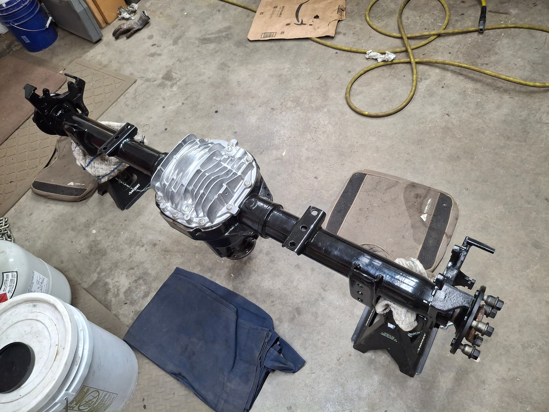
I wire-wheeled, scrubbed out, and pressure washed the housing and will be painting it while I await the rebuild parts.
1 Like
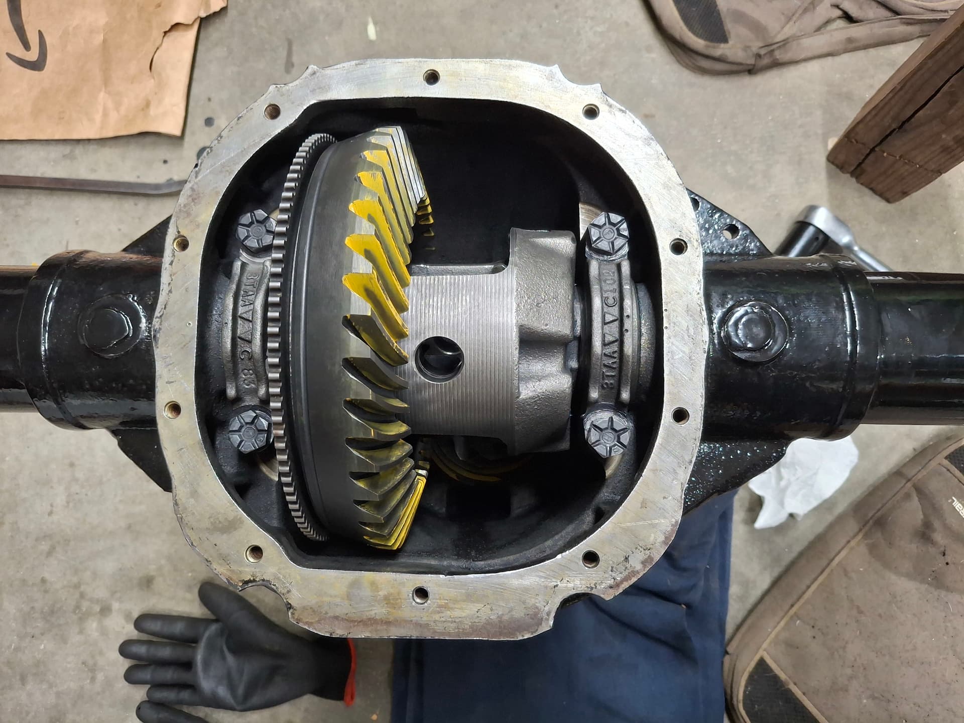
I rebuilt the rear end bearings and posi clutches. I used a USA Koyo bearing kit that turned out to be Japan-made for the carrier and pinion bearings and USA-made for the wheel/axle bearings. Cool by me. The posi race frictions and steels are USA Alto. Since I am reusing the ring and pinion gears, I maintained the carrier spacers and pinion shim that I took out since the gears are already matched. I’ve been told by those along the line who have taught me about such things that fooling with pinion and ring-gear depth with used gears almost always results in bad whining, but I’ve never fooled with them to find out it that’s true. It makes sense, though.
The pinion and backspacing depth looks good from the paint pattern, and I have 0.010" backlash out of a spec of 0.008" - 0.012". I’m 0.003" too loose on the carrier bearing preload using the original spacers. The spec calls for 0.006" on each side for a total of 0.012" preload and I’m at 0.0045" each side for a total of 0.009". I doubt there will be an issue, but I can order wider spacers and swap them later if the carrier is too noisy–if I can even hear it over the exhaust.
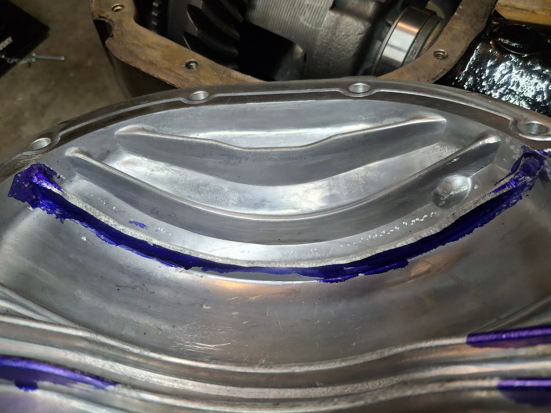
I obtained a finned aluminum cover to help with cooling. The cover has fins that extend inside the housing, and one of them hit the ring gear. I had to use a die grinder and burr bits to shave off 1/4" of fin, but otherwise it’s a really nice piece. Other perks are it has a top fill hole, a drain hole, and a temperature sending unit hole (which I plugged). For some reason it has a baffled vent too even though the housing is vented, so I just plugged that since I think the housing vent will likely see less oil in the vapor due to drop-out than if I vented directly from the center section.
I also converted the drum brakes to disc using a set of caliper brackets I took off a car at the pick-a-part. I drilled out the rivets and removed the backing plates for cooling. I want to give a shout-out to @Bob_Alder who was kind enough to let me use his sandblasting cabinet to clean up the caliper brackets along with some other small parts, saving me hours with an angle-grinder wire wheel and bench wire wheel. Plus we got to have a nice lunch together.
Post Alert Pings:
@jonUU
@Sportsracer
@Datsun78
Justin,
I am enjoying your updates very much. You have mad fab skills. I think you live in Aurora, as do I. My blast cabinet may be closer than Bob’s, if needed.
Mark
1 Like
I appreciate it, Mark. I’ll keep you in mind for the blast cabinet for sure.
Relocating Rear Upper Shock Mounts
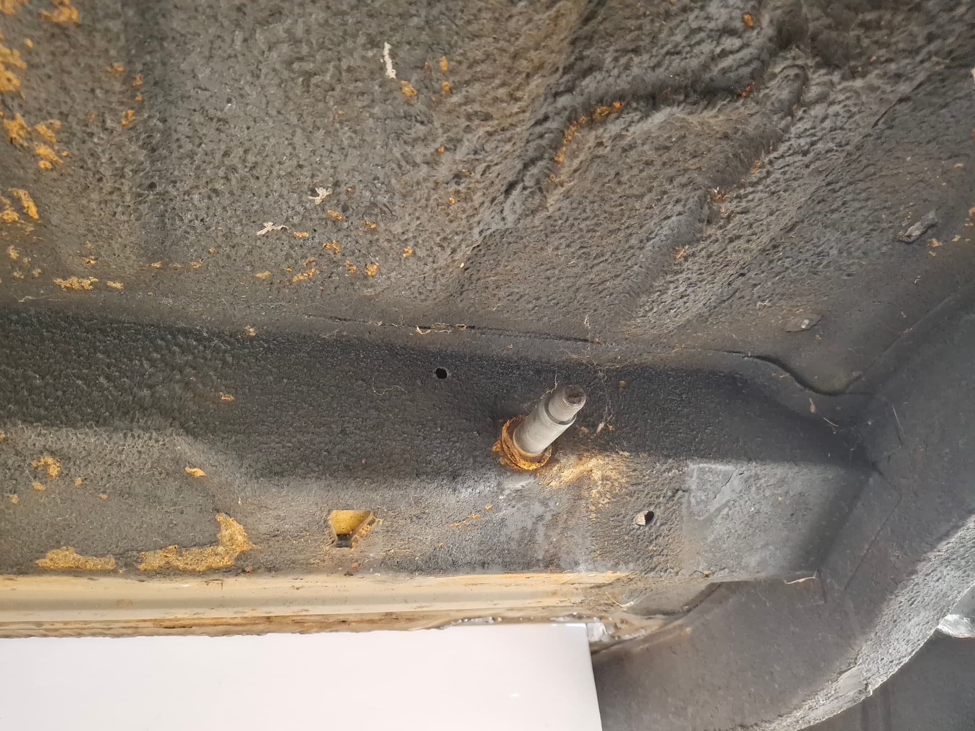
With the rear end ready to install, I turned my attention to the rear shocks. The factory shocks have a lot of lean inboard from the lower mount on the leaf-spring plate to the top mount in the unibody floor. The floor pan in this location is a double-wall with a 3" cavity. I drilled new holes through both floors as close to the rear frame rail as possible and welded in a 1" x 0.120" spud. The upper shock mount now, rather than having the inboard 5/8" study, uses a 3/4" bolt that goes through the shock, through the spud, threads into a nut welded to the trunk floor, and is backed by a jam nut.
Rear Lower Shock Mounts
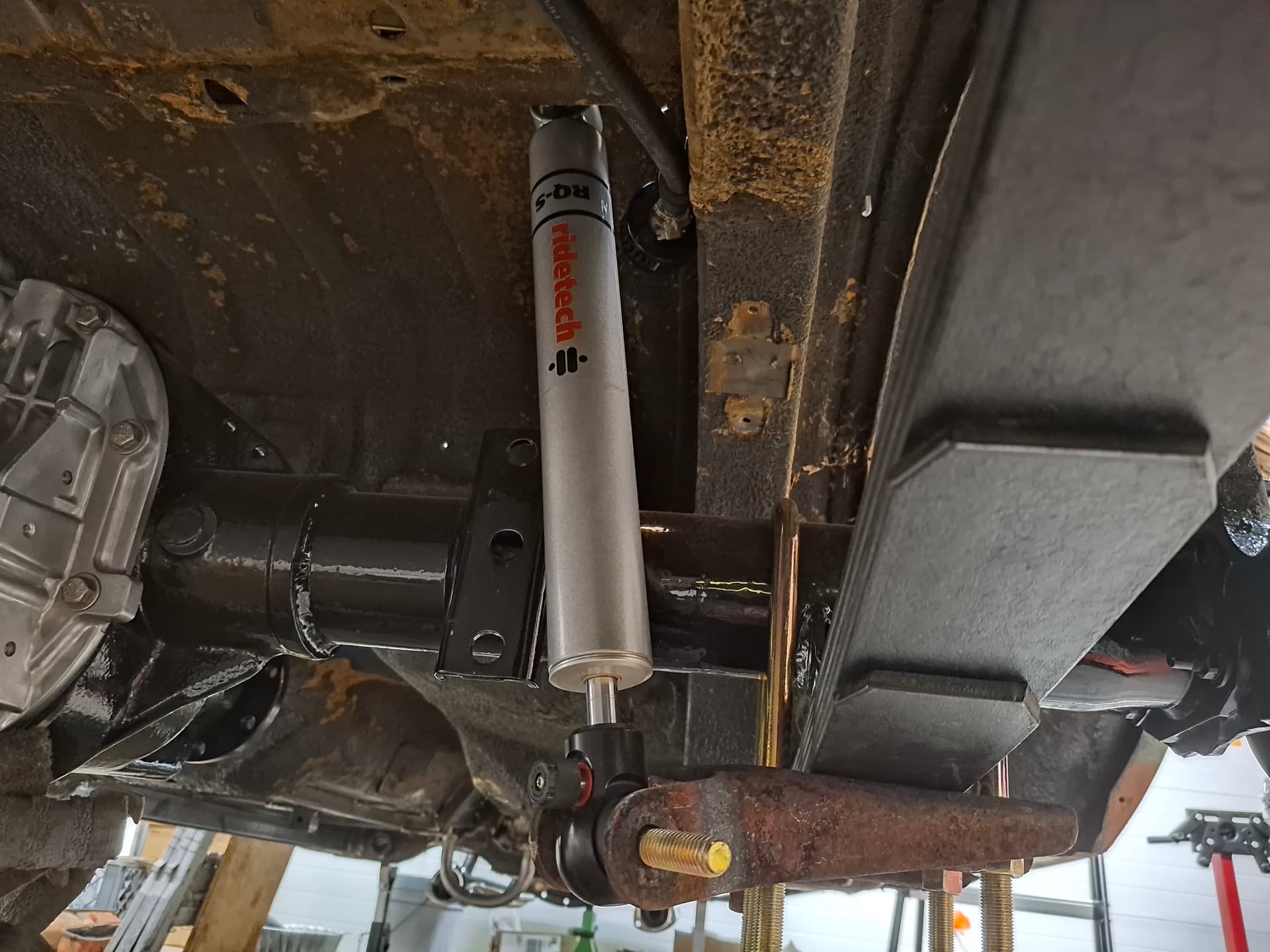
The next issue was the lower shock mount. The Mopar A-body has extremely limited monotube shock availability because the shocks fall between either too short or too long for off-the-shelf units aside for expensive options like Penske. RideTech monotube single (rebound) adjustables are about the only shock that fit, but they have limited compression travel on a stock configuration and even worse with my 1" lowered leaf springs, 1.5" raised spring hangers, and stood-up shocks.
In the factory upper and lower mount locations, the RideTech shock provided 2" remaining compression travel with the car at rest. Once I stood up the shock, I had a puny 1" of compression travel left. The upper shock mount couldn’t be moved up without cutting a hole in the floor and having the shocks stick out of the floor into the driver’s compartment, so the lower mount needed modification.
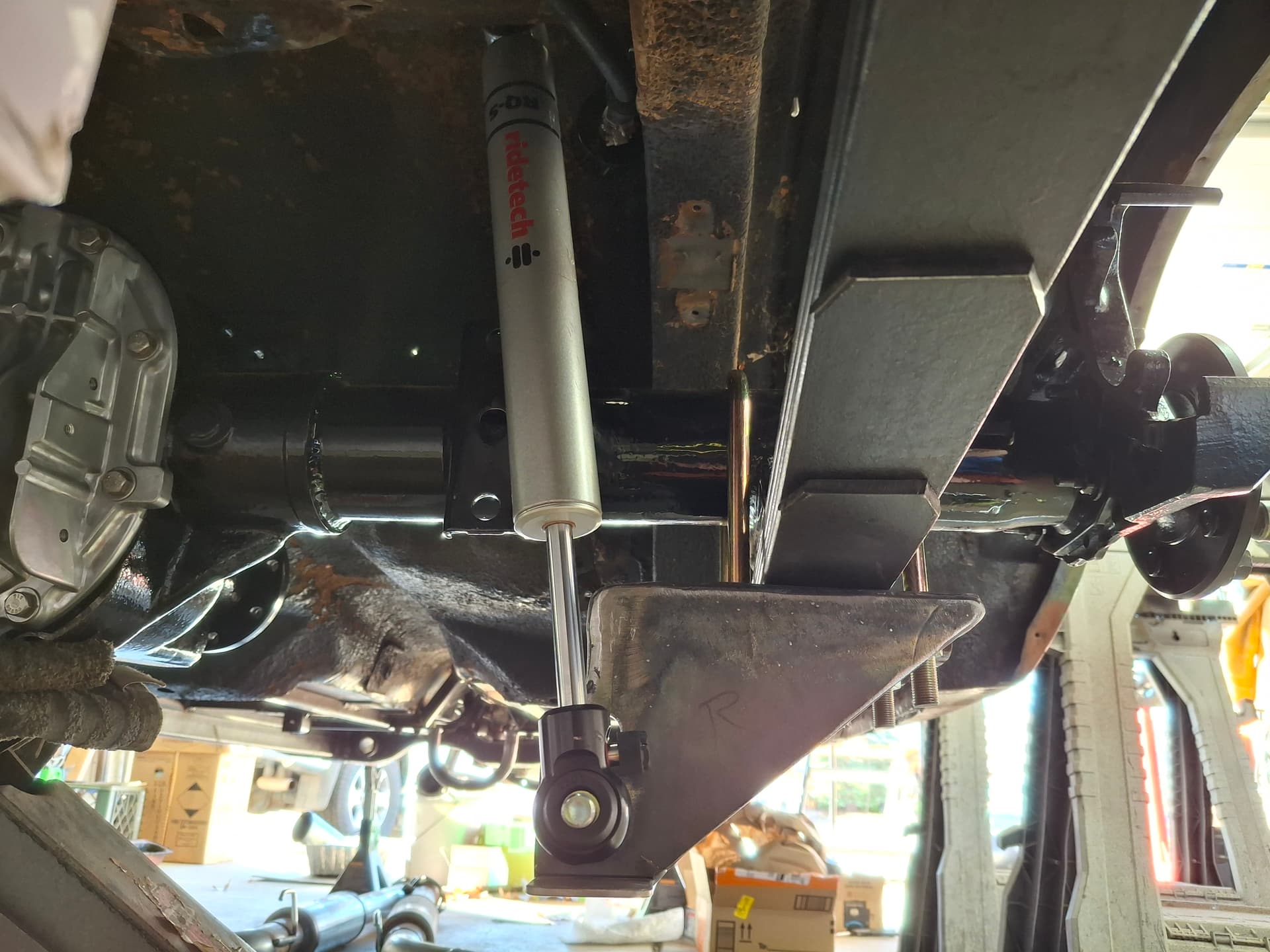
As much as I would prefer that the mounts not hang lower than the rim in the event I lose a tire, the additional 2" lowering necessary puts the bracket 3/4" below the rim. In all likelihood, some of the tire bead and sidewall will remain with a flat keeping the bracket from contacting the ground.
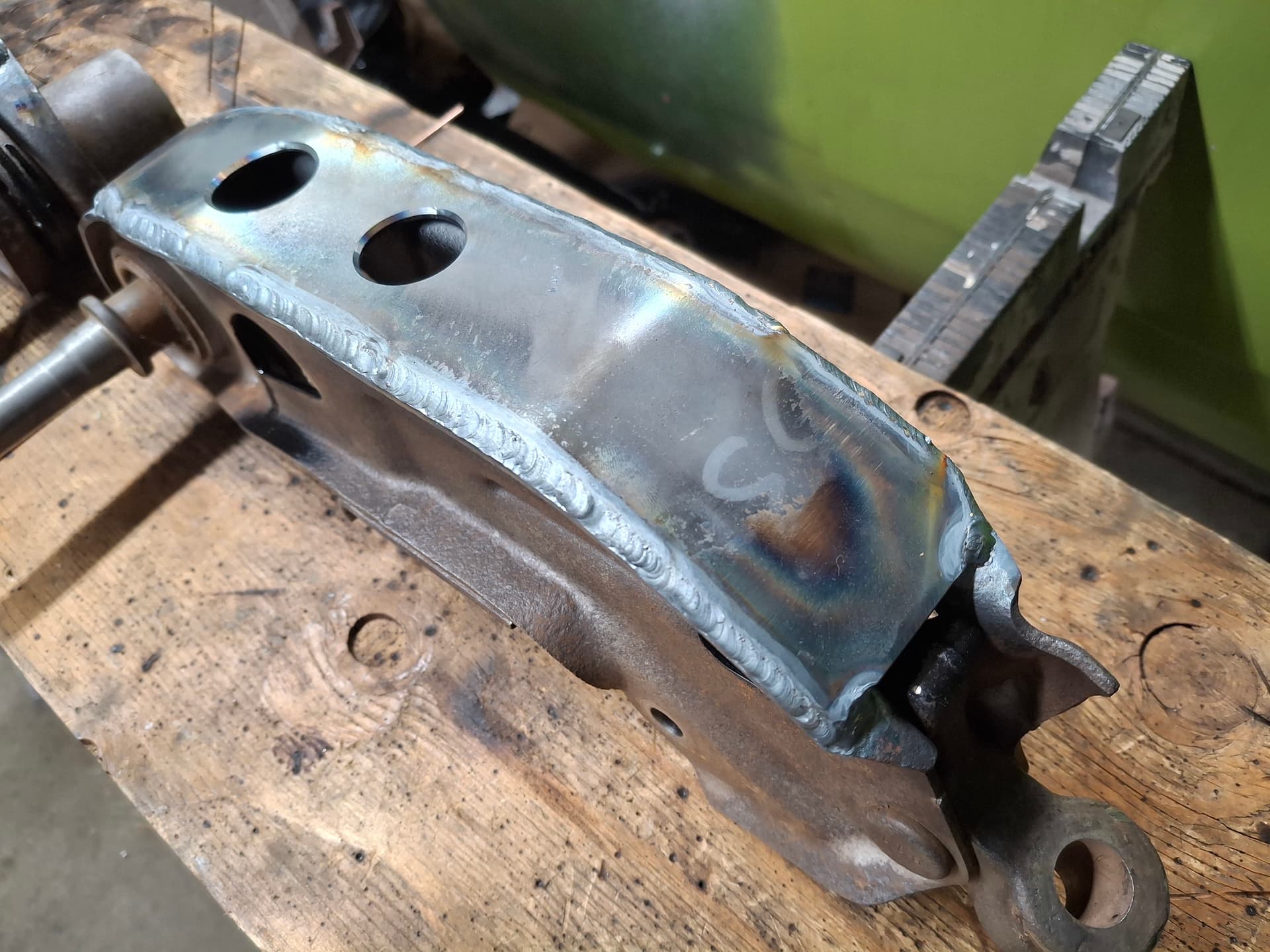
I cut the factory shock ears off the leaf-spring plates and fabricated a 3/16" plate mount with a triangulated gusset on the front (not visible in the photo). I also welded a skid plate on the bottom to cover and protect the lower shock eye and rebound adjuster in the event of contact with the debris or the ground. I drilled two mounting holes–the lowest for the shock position with the leaf-spring hanger raised 1.5" and the highest for if the leaf-spring hanger is in the factory location 1.5" lower. I used a new 3/4" thread x 5/8" stud. With this configuration, I have 3" of remaining compression travel and 5" of extension travel with the car at rest.
I intend on experimenting with fabricating a curved aluminum sheet baffle that will go on the front of the shock mount bracket to direct air onto the rear brakes, so that’s to come.
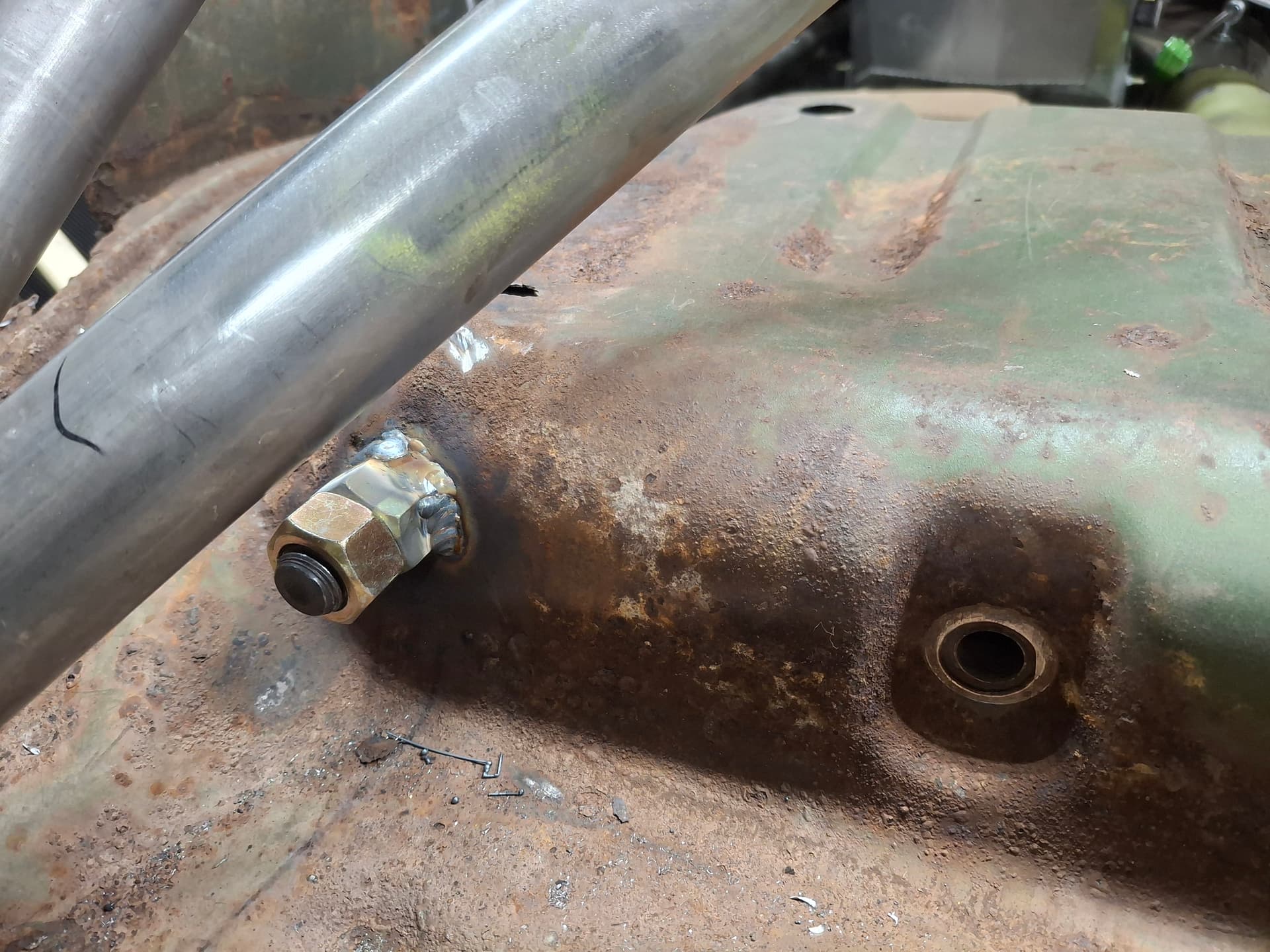
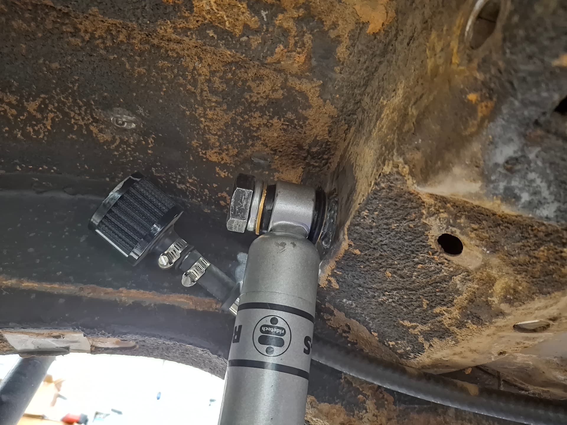
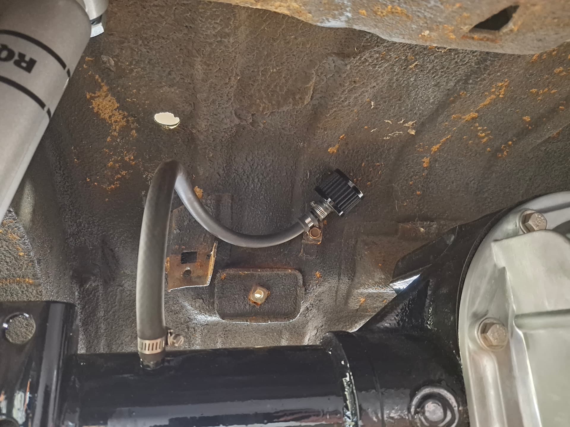
Fuel Cell and Rear Axle Vents
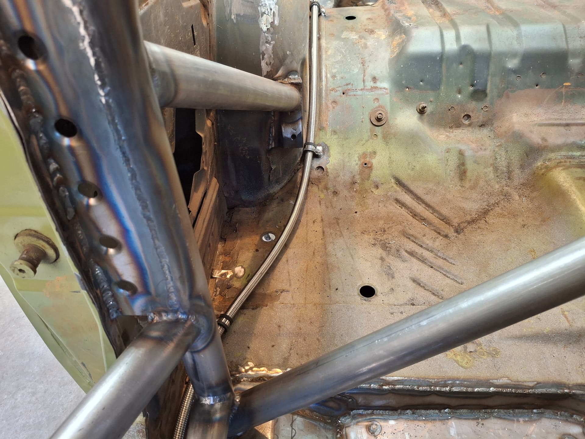
Lastly for this installment, I finished the fuel cell vent (see the breather in the photo above of the top shock mount) and the rear axle vent.
Sweet! Always a treat to see your work AND the accompanying photo documentation with well-written narrative. Might the extended lower shock mounts be vulnerable if the car inadvertently straddled the curbing?
Thanks @jonUU. Yes, the curb is a concern, but I think the mounts are close enough to the wheel where they will not contact the curb so long as the tire is on it. Now, if I put the tire off the curb into the dirt where that side drops, there will likely be contact. My hope during testing and tuning is that I find the suspension doesn’t require 3" of compression travel where I can move the shock to the higher hole and lop off 1.5" of the bracket.
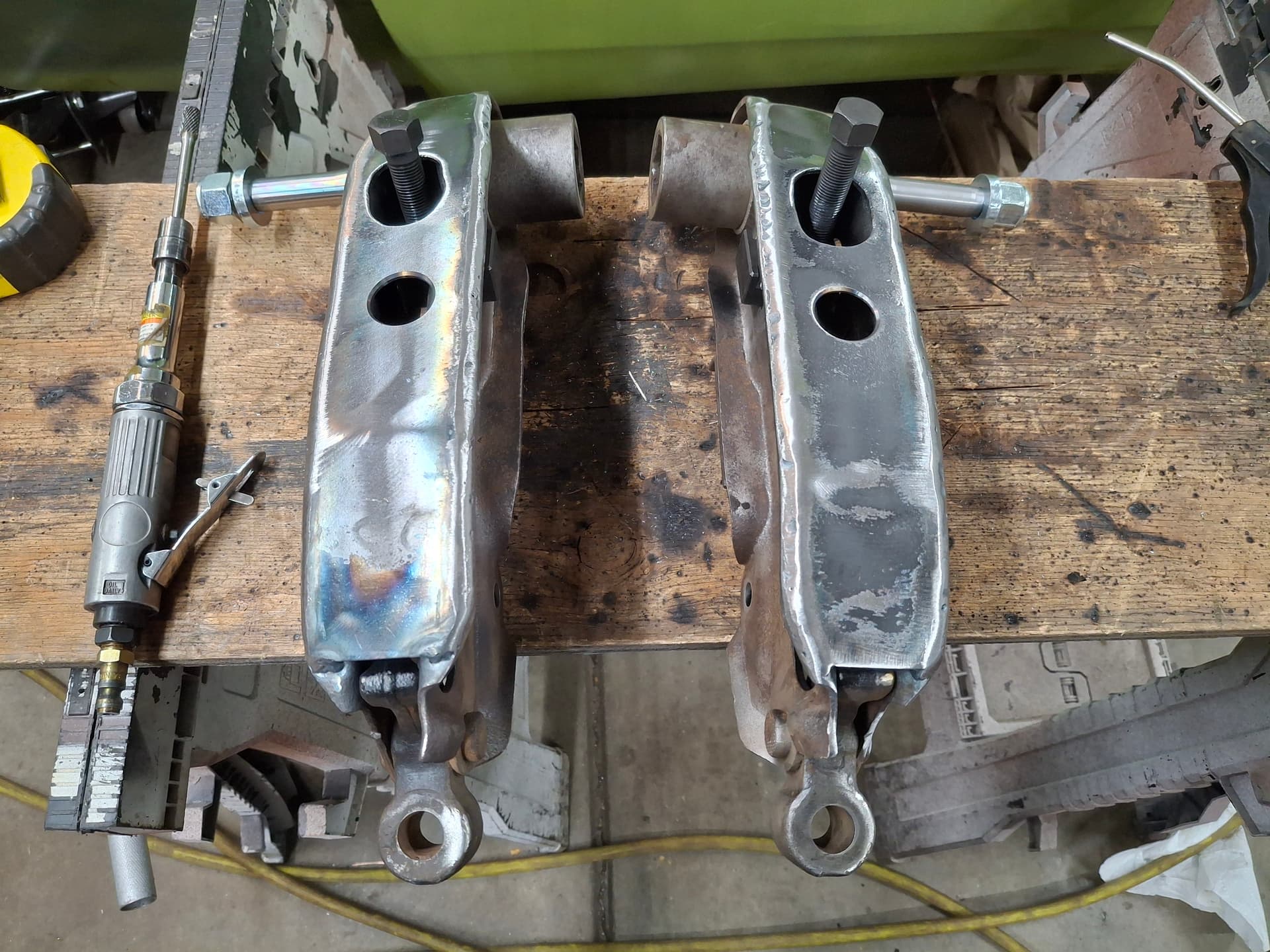
Front Lower Control Arms
Keeping to the 1981 GT-1 spec, I must maintain the factory lower control arms but can reinforce them. The Mopar control arms are two stamped pieces with open top and bottom, and the bottoms have a tendency of flexing. I cut 1/8 plate gussets with the elongated hole for the torsion bar adjuster screw and the center hole to access the bump-stop nut even though I likely won’t be running that stop.
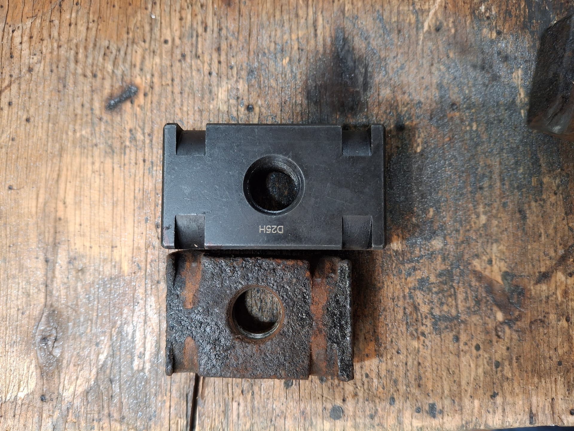
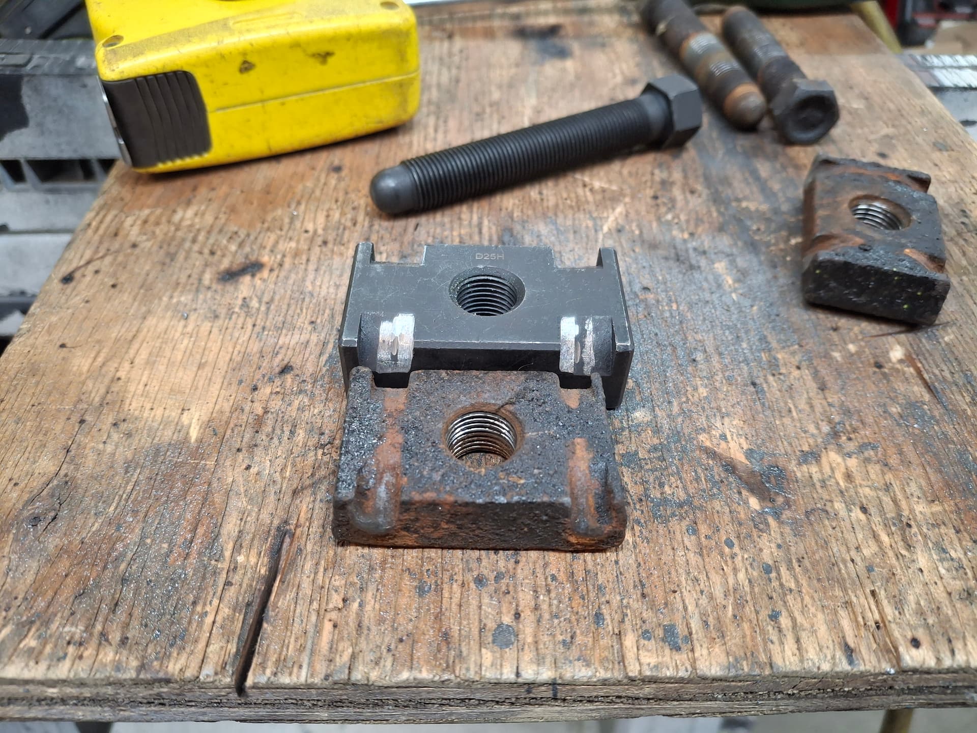
Torsion Bar Adjuster
I experimented with something I haven’t run across, and it looks like it will work. The factory A-body torsion bar adjusters are a crudely forged 1/2" thick plate and hardened screw. I was concerned that the strain of the 1.24" torsion bars and track duty could flex or even bend them over time since the largest production torsion bar ever used on A-bodies was a 0.920" in 426 Hemi cars, and mine are 1/4" larger than those.
I couldn’t find any beefier aftermarket blocks, so I decided to get a set of aftermarket B-body adjusters that are made from 3/4" thick billet alloy steel with grade-8 adjusters. At $120, they aren’t cheap to be modifying, but I took the chance. The blocks have curved grooves that locate on the crescent-shaped holes in the control arm to where they will pivot the adjuster screw angle as you put in or take out turns on the screws to raise/lower the car. To make the B-body blocks work, I had to use a burr bit and shave off 1/32" off of the crescent side of the control arm and grind and file the slots in the block wider. The inside wall of the slots are now a very snug fit with the inside walls of the control arm capturing the block to where I don’t think the wide grooves will have any impact since the block can’t move sideways once I preloaded the torsion bars. The only time they would be able to move is if the adjusters are backed way off and the spindles are dangling.
Lower Control Arm Pivot Shafts
I pressed out the original pivot shafts, cut the inner bushing casing, and hammered it out with a cold chisel. The new units are Delrin bushings (don’t require lubrication) and billet alloy steel shafts.

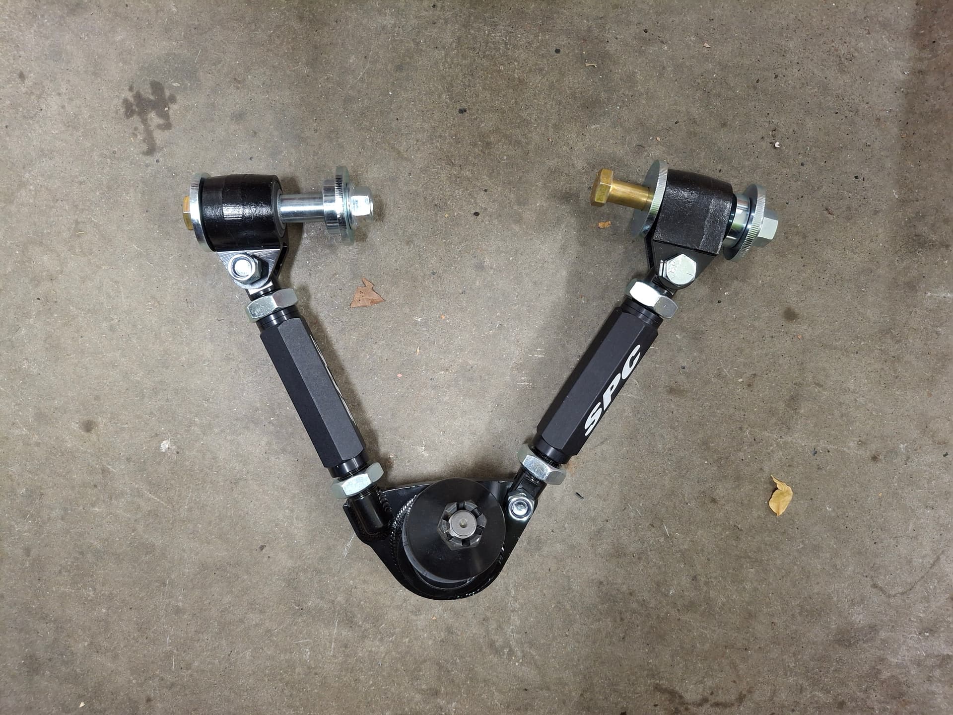
Upper Control Arms
The wimpy factory stamped-steel upper control arms are in the sell-or-scrap pile and replaced with SPC fully adjustable units.
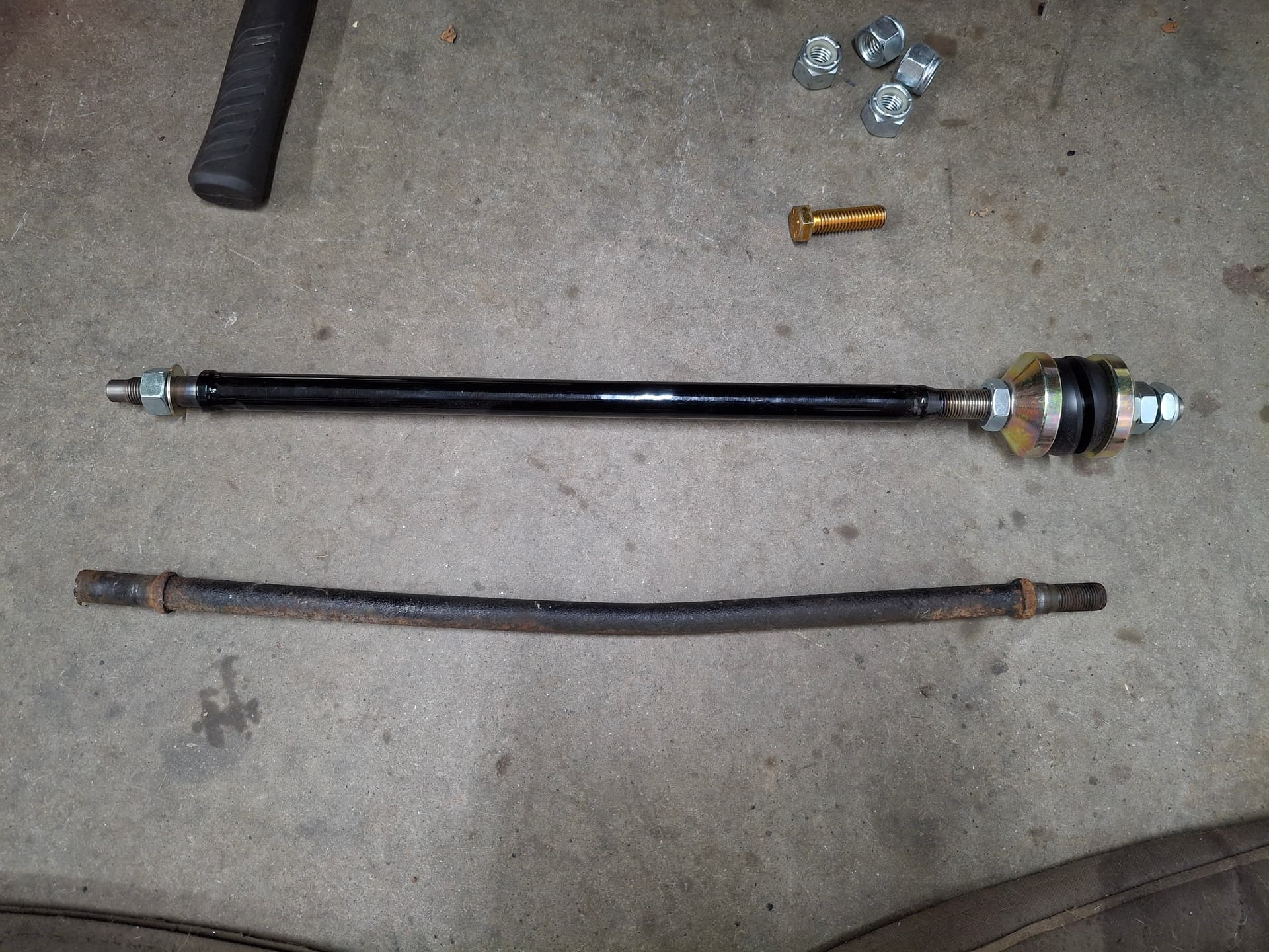
Strut Rods
The factory strut rods are nonadjustable, susceptible to flexing, and use rubber bushings. The photo shows how one of my strut rods was bent, likely from someone jacking up on it. With the caster/camber capabilities of the new upper control arms, the factory struts are unusable to keep the lower control arm properly aligned, so I replaced them with a set of alloy steel fully adjustable rods with Delrin bushings.
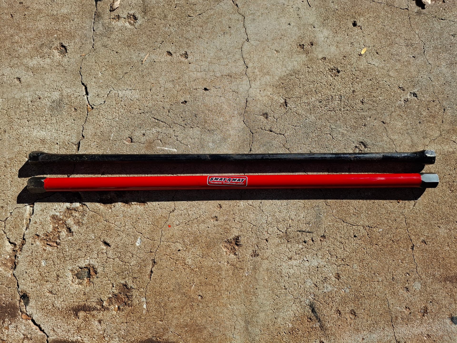
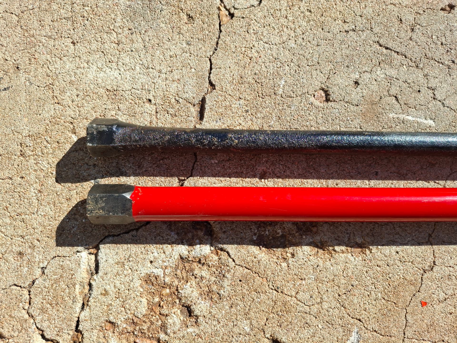
Torsion Bars
Ah, the piece de resistance of the front suspension. . . the new 1.24" diameter torsion bars. The factory bars for this car were 0.850", which kind of got the job done for 318 and 340 street cars. The most outrageous 426 Hemi cars got 0.920" bars. My brainchild gets custom new 1.24" bars, which are just 0.01" smaller than the actual hexagonal socket. They will present a major fitment issue with the #8 header primary tube on the right side, however, that I’ll have to deal with down the road.
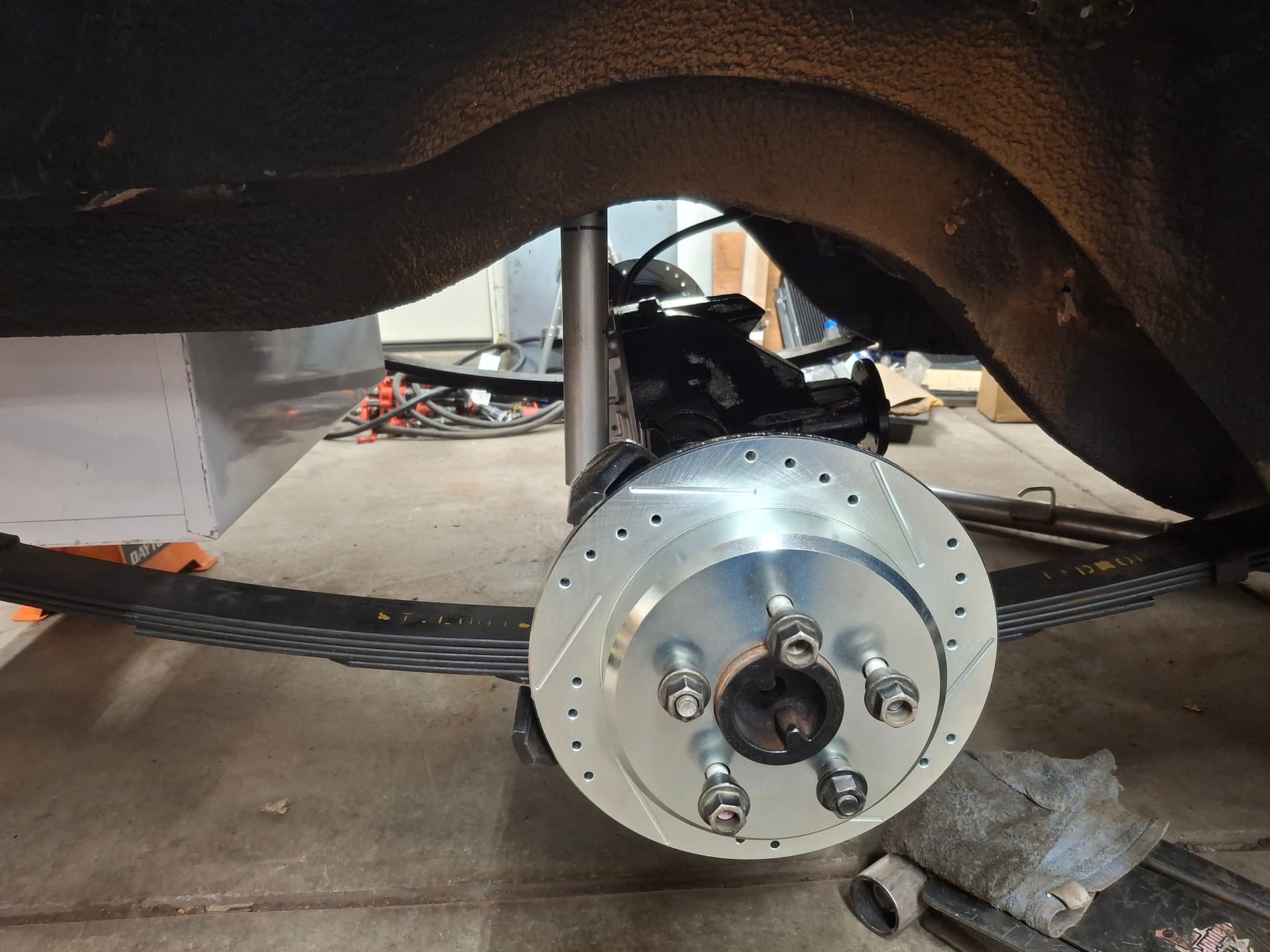
Spindle, Ball Joints, and Disc Brake Upgrades
While I neglected to take a photo of the spindles and brakes before installing a wheel, I upgraded the front spindles from the smaller ball joint units to 1973 - 1976 A-body (e.g. Dart, Duster, Demon) forged spindles and large forged ball joints. The 11.75" rotors with Mopars “big” 5-on-4.5" bolt pattern (the largest diameter rotor that will work with 15" wheels) are drilled and slotted and take Wilwood four-piston calipers.
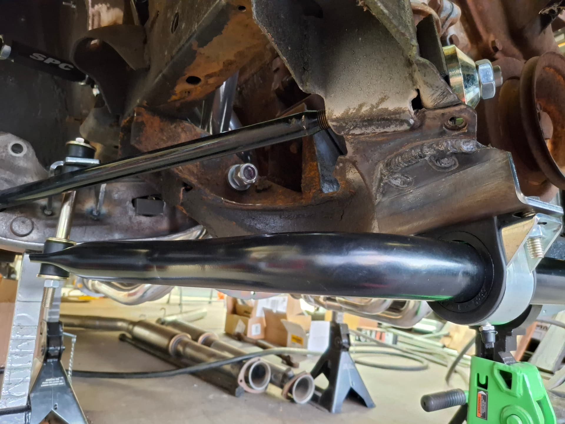
Sway Bar
With the I welded in the lower control arm mounts and hanger mounts for the Hotchkis 1-1/2" hollow sway bar.
Post Alert Pings:
@jonUU
@Sportsracer
@Datsun78
@Bob_Alder
1 Like
It all looks very stout indeed, I hope with those beefy torsion bars you don’t induce chassis flex. I don’t know how those cars were set up “back in the day” and likely there isn’t much online regarding how the Sam Posey (and others) cars were set up. I remember hearing that the 60’s & 70’s vintage stock cars ran very stiff springs and used chassis flex as the suspension. Not very tunable!
Not being familiar with the GCRs for big bore cars, what is the minimum weight? Are you getting close? Lots of reinforcement is a good thing as long you don’t cause yourself a weight penalty. I guess to be “period correct” you could always acid dip the body to save a few pounds ![]()
@Sportsracer, alongside safety, a major consideration when I designed and fabricated the subframe and cage system was to stiffen the car in preparation for the torsion bars, leaf springs, and track duty. When I first put the stock car on jack stands to begin work, I could jack up one corner 3" before any of the other three tires would really budge. Now, if I jack up any corner at even 1/16", the entire car pivots on the opposite diagonal corner (i.e. if I jack up the left front, the right front and left rear come off the ground immediately). Of course, dynamics under load while cornering will differ, but the car now seems extremely stiff to where, hopefully, the suspension does the flexing.
I am very fortunate to have two mentors who have scouted much of this territory before. Jess Neal used to be more active in the club and runs a 1971 Barracuda T/A tribute car #42 at the Pikes Peak Hill Climb (currently building a new engine). I met Jess last year when I joined RMVR. Jess introduced me to his friend Brian Garcia (British pronunciation) out in Illinois who, what would you know, built and has raced for decades a 1969 Barracuda fastback. The Mopar road-racing community is tiny, so I’m fortunate to have met these heavy hitters in it. We three have great fun discussing the project, and I’m a sponge to their input. Both of their feedback to me when discussing the cage system is throw everything at it. Even with a stout cage, Brian found stress cracks in his car’s unibody framework after a few years of track duty that required reinforcement, so I reinforced those locations on mine from the start. Their feedback on torsion bars is to go as big as practically possible from the start since they started smaller and have made expensive incremental upsizing changing with improvement at each step. Brain currently runs the largest bar possible at 1.25" to my 1.24". The only way to go bigger is to cut the chassis socket and control arm socket off a B-body car, cut the sockets off the Barracuda, and weld on the B-body sockets, but I can’t find empirical or anecdotal evidence to suggest going larger than 1.25" on a small-block car improves or harms performance.
To your question about weight, with a displacement of 306 - 366, 1981 GT-1 minimum weight without driver and fuel on my spec sheet is 3,100 lbs. While I am behind in my thread posts and will get to this part of the build post eventually, I put the car on a set of scales this past weekend and was very happy to see what I found for both weight distribution and overall weight. Keeping in mind I have at least 300 lbs of parts not bolted on or not placed in the car for weighing (exhaust tubes/mufflers, driveshaft, windshield/back window, radiator, gauges/wiring, harness), the car comes in at 2,600 without me or fuel. While I may be incorrect, I think I’m going to be hard pressed to meet the 3,100 lbs without adding ballast. Current front-to-rear ratio with me in the car is 55%, and it’s only 40 lbs off of being 50% left to right. Ballast to meet the minimum weight would be a good problem to have since I can place it in the rear and to one side to get even closer to 50% all around, although I’m realistic that I will be fortunate if I can get anywhere close to 53% front-to-rear. I am very happy with what I saw on the scales since I was expecting to be overweight at this point with as much steel as I put into the subframe and cage. More of the weight details to come when I get to that point.
Justin
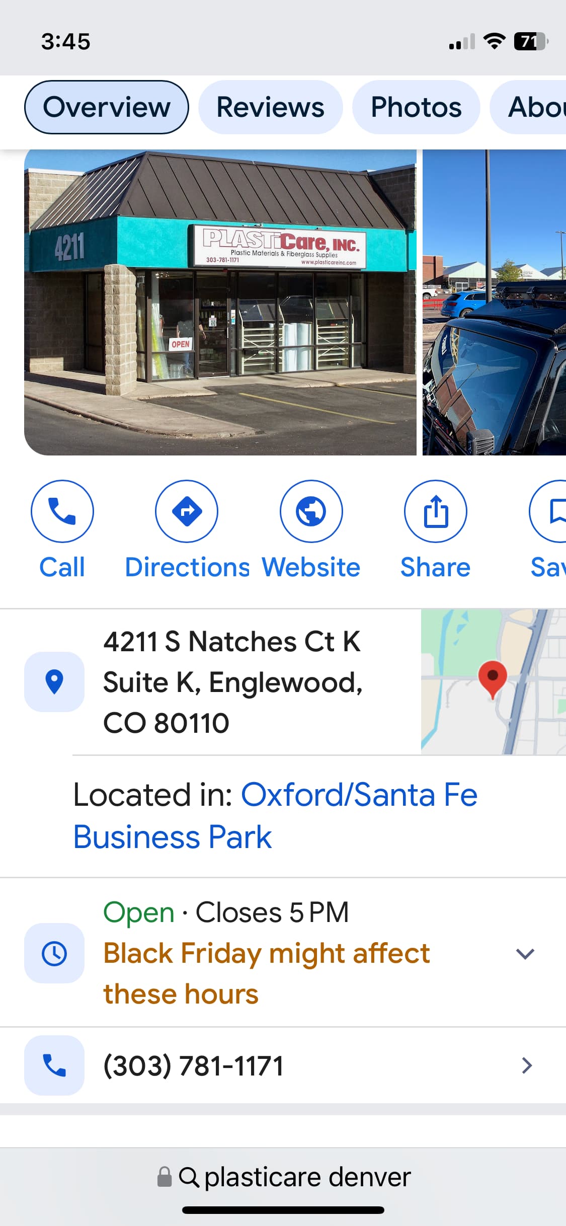
You are truly blessed to have 2 mentors to help guide you. Sounds like you’re well on to being competitive. Your weight target looks to be in sight, how about polycarbonate “glass” if weight becomes a problem. There is a supplier in Englewood.
Do you think you’ll be on track next year? Looking forward to seeing you and the car.
When I rebuilt my 2 bobsy sports racers I was able to get a lot of info from the son of the man who originally built my cars. He has all the original blueprints and is a wealth of knowledge regarding these rare cars.
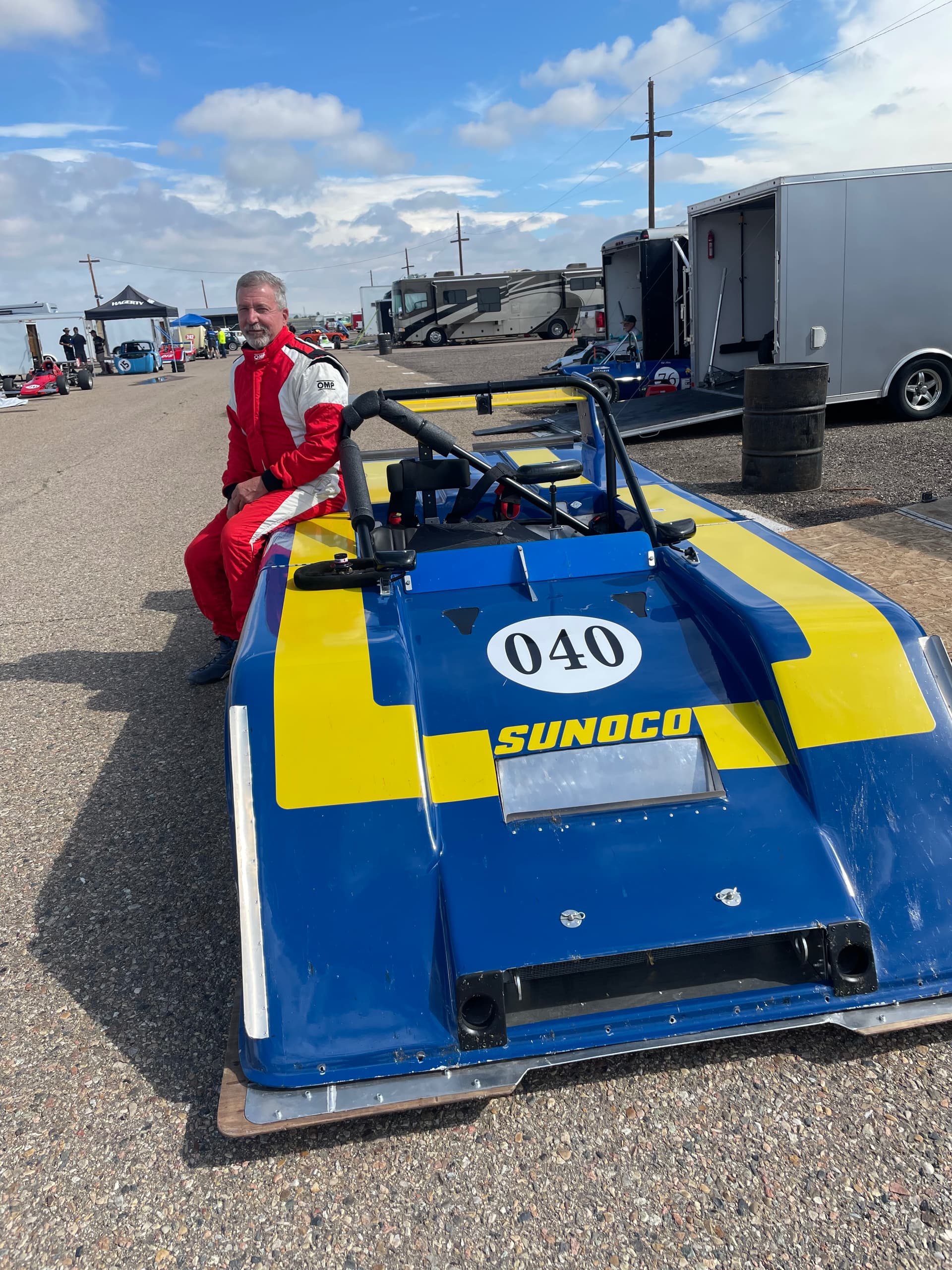
The one I currently race
This one will be for sale in the spring
@Sportsracer, my intention is to run a glass windshield (I prefer them over polycarbonate due to scratching and the discolored glare common in the later) and a polycarbonate rear window. I’ve gutted the door and quarter windows and won’t run those. I’ve researched some suppliers of polycarbonate sheet in the Metro but haven’t nailed down someone. Who’s the supplier in Englewood you recommend?
My goal is to be on track in 2026. I’m taking drivers school in the spring and hope to be testing and tuning the car down at La Junta and on RMVR Fridays by late spring through the summer. Assuming I can get a basic paint job slapped on in time for the car to look presentable, my goal is to enter the 2026 RAKC.
Once I know I don’t need to do any more major cutting/bending/welding on the car, I’m going to have it media blasted, and I’ll do the body work and spray a proper vintage livery over the 2026 winter if things pan out that way.
Exhaust
Taking my lunch break from working on the car, I figured I’d catch up on an older project that I never posted.
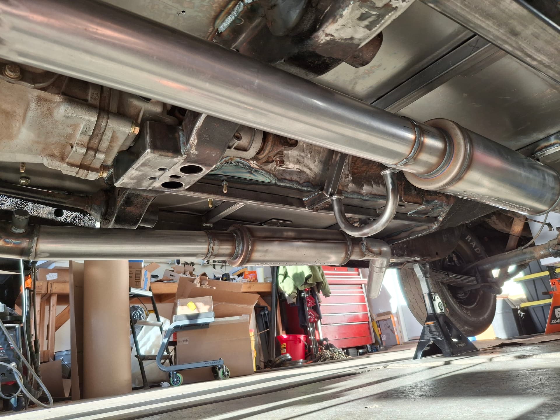
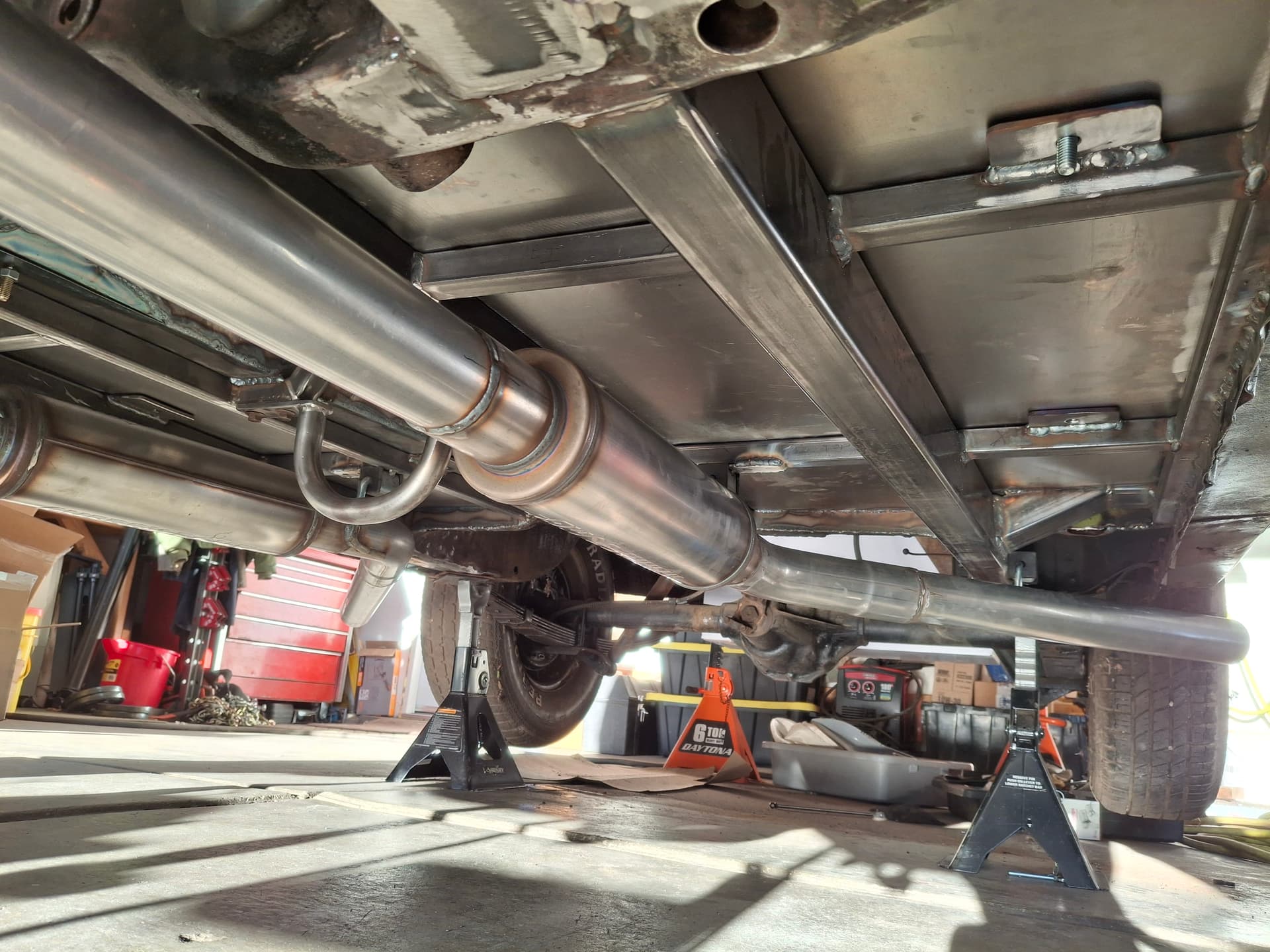
I fabricated a 2-1/2" exhaust system. I welded in oxygen sensor bungs after the collectors to use an air-fuel ratio gauge for testing/tuning. I used 20" long Cherry Bomb “Salute” straight-through mufflers, which are a straight 2-1/2" perforated tube surrounded by stainless steel wool–essentially a glass pack but that won’t deteriorate and blow out. I’ve run the dual-chamber Salute on street hot rods and like the tone and performance, so I thought these are worth a shot since they are one of the more unrestricted designs I found that provide some muffling over the really short single-chamber bullet mufflers. I’m going to need to fire the engine to tune it, load the car, and to cruise the car to meet-ups to promote RMVR, so I want some muffling for my neighbors, although I suspect this system is going to be very loud regardless. I used 3/8" diameter hanger rods with rubber-isolated mounts and welded them in to where each exhaust leg slides back into the hangers from the front and is then locked in place with the collector flange to where any movement is impossible.
Justin
Plasticare is whom I’m referring to:
Sounds like it will be a sweet runner. Can’t wait it on track this coming season.
Best
Tom
1 Like
Thanks, Tom @Sportsracer, for the reference; I’ll stop by when I’m ready since I’ll need at least a 4’ x 4’ sheet for the rear window.
Fuel Cell Modification
I needed to address the fuel cell since it didn’t have foam and used a swinging sending unit. I want a fuel gauge since I’ll be driving the car on the road to cruises/gathering to promote RMVR. With much digging through different manufacturer catalogs, I found a Tanks Inc. vertical enclosed sending unit that is the correct 13" height for the tank and the correct ohms for the fuel-level gauge.
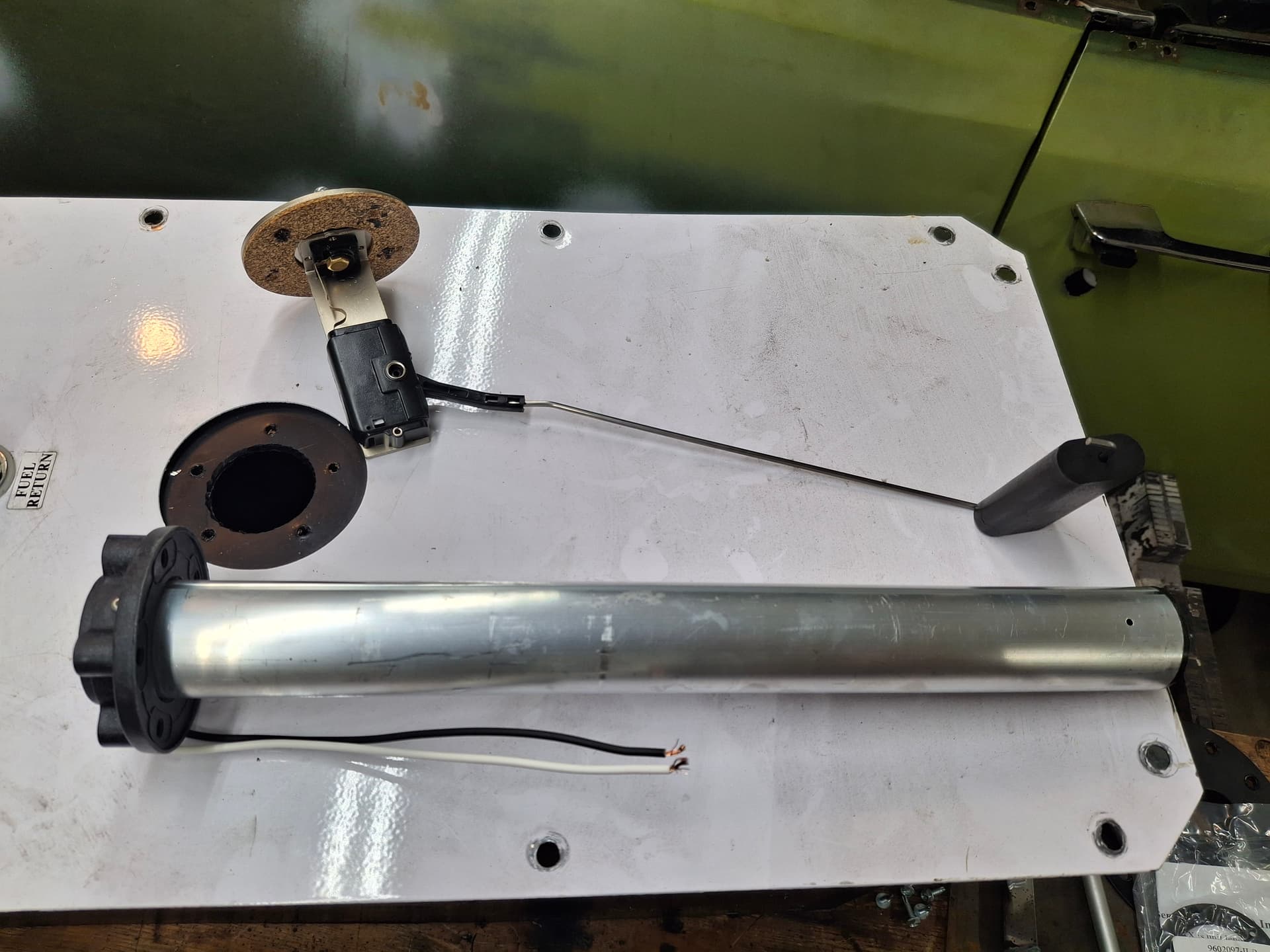
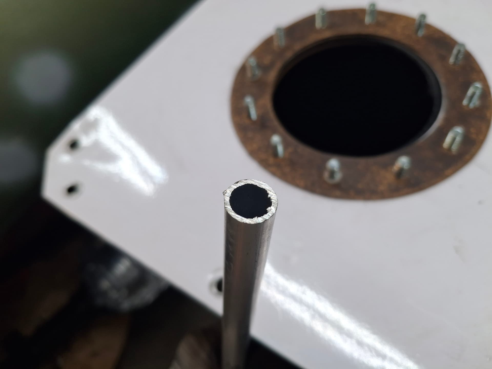
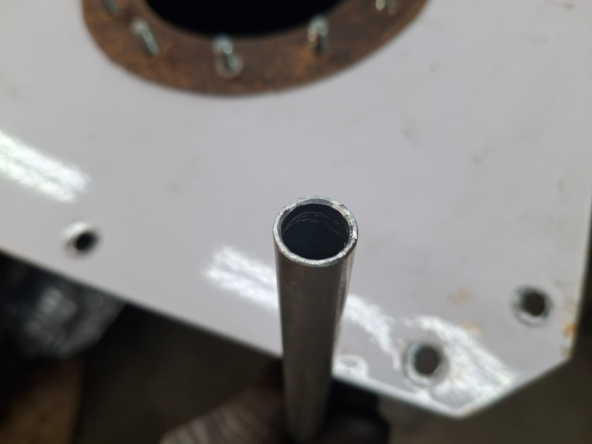
While I had the filler plate removed from the tank to install the foam, I decided to check the quality of the pickup tube, and I’m glad I did. The tube’s end was crudely cut with burrs encroaching on the opening, so I smoothed everything.
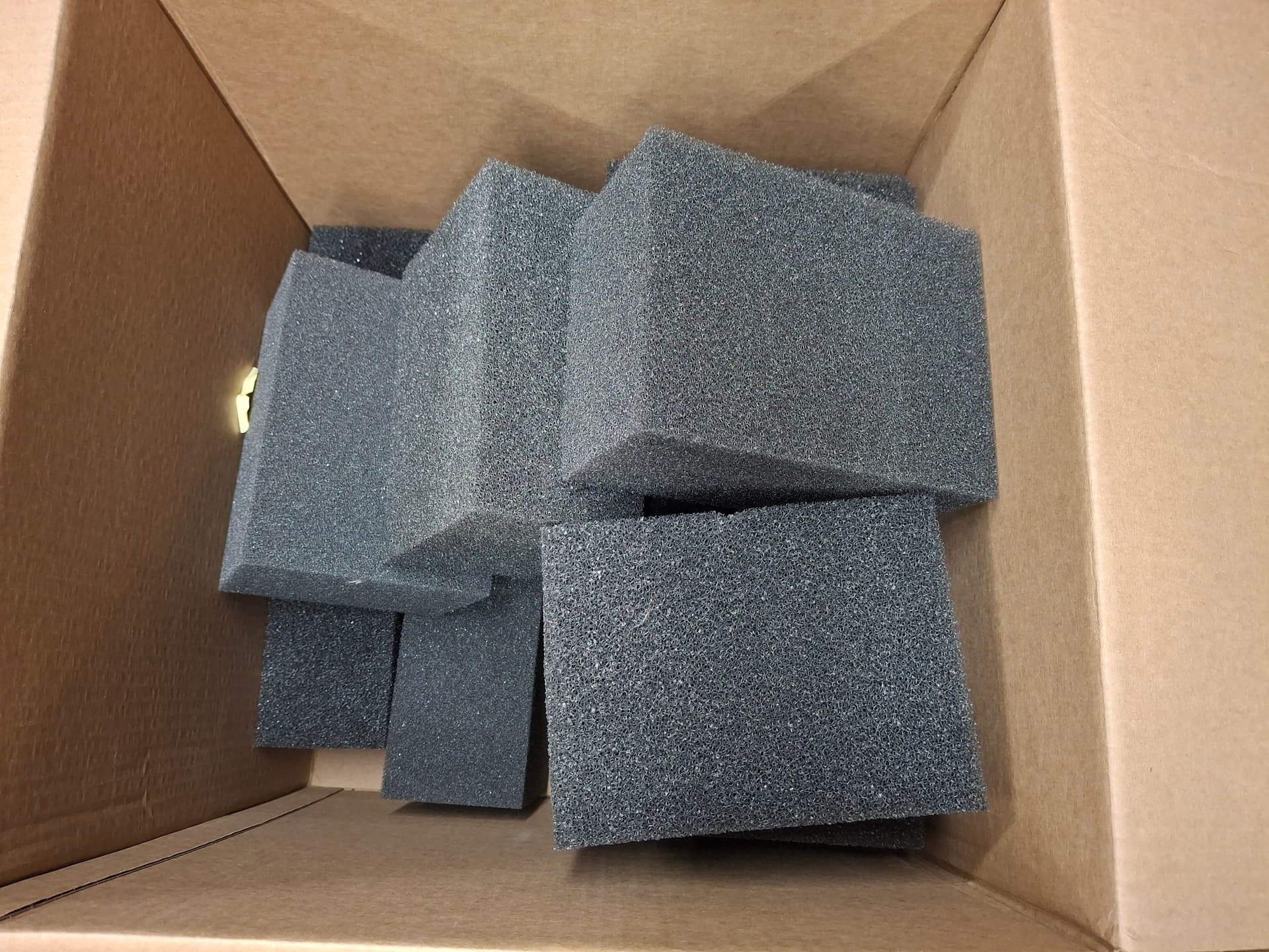
I then fought twelve blocks of Speedway Motors foam into the tank, cutting a crescent down two rows of six blocks for the sending unit.
Fuel System Plumbing
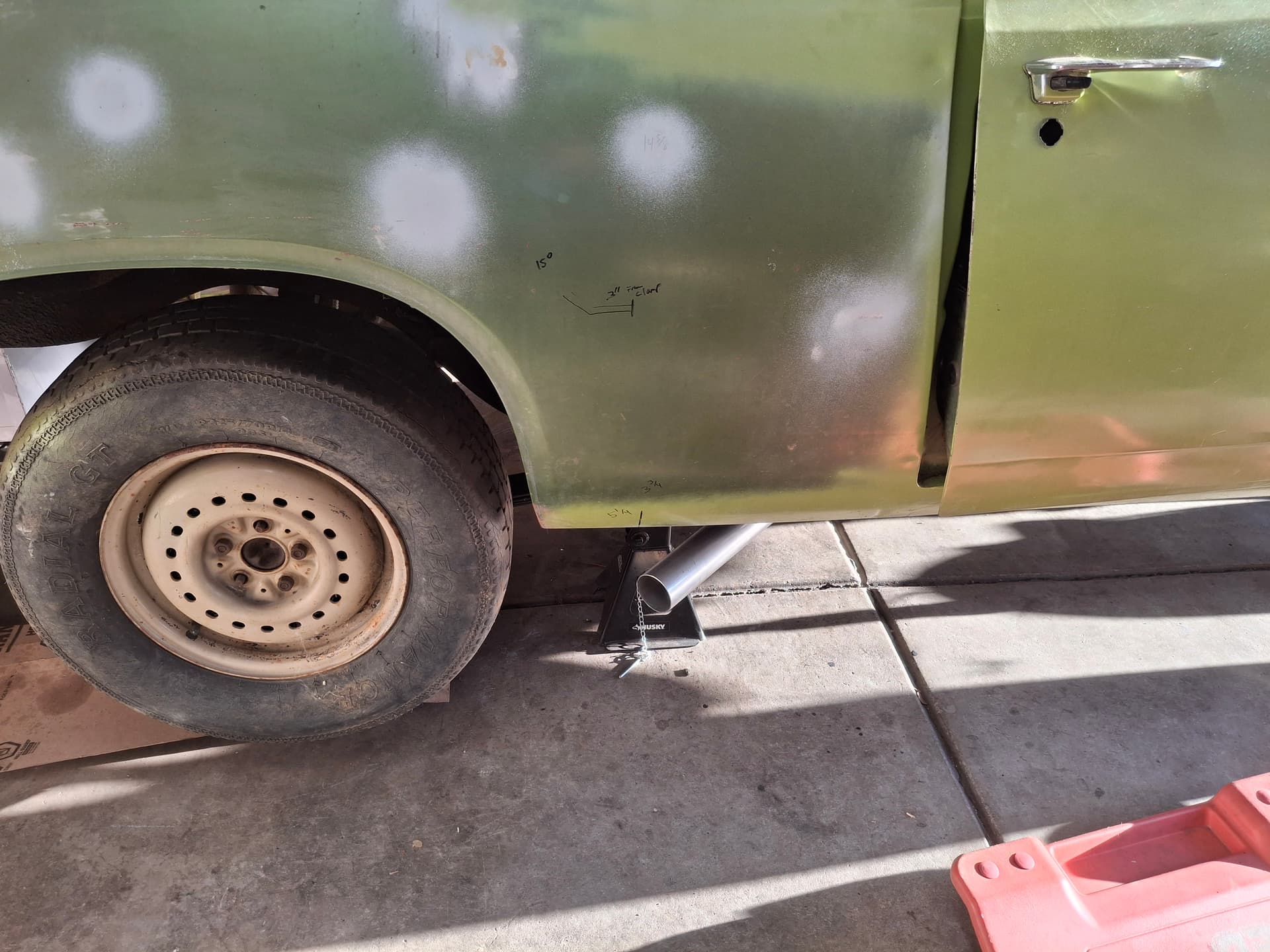
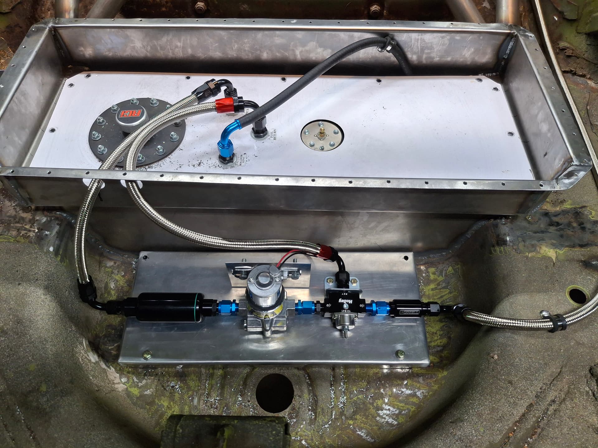
Initially, I wanted to run 1/2" aluminum hard line from the tank to the engine compartment on the underside of the car since I prefer not to have fuel and oil hoses in the driver’s compartment if I can help it. Unfortunately, there was no way to run the fuel under the body without it either running parallel with and 3" away from the exhaust tube and muffler or having to run low along the rocker panel and bend far down around multiple crossmembers where there would be a safety concern if a jack, gravel, or other debris were to hit the line even with gravel guard installed. My plan changed to running the fuel through the driver’s compartment, which meant I had to run braided stainless hose per the rules.
I plumbed the system with -8 hose from the tank up to the intake manifold and into a -6 manifold at the carburetor. I built an aluminum mounting plate in the trunk for easy mounting and access to components and to allow me to remove the filters with the entire unit out or where a drip pan will catch fuel for ease of cleaning. The tank outlet hose runs into a FITech cleanable mesh 100-micron filter, into a Jegs 140 GPH electric pump, and into a Holley 140 GPH return-style pressure regulator, into a Russel 40-micron cleanable mesh filter, and up to the engine compartment. The fuel return plumbs from the regulator back into the tank. For those interested, I noticed when researching fuel pumps that the Jegs brand 140 GPH pump looks identical to the Holley “Black” 140 GPH pump at half the price during holiday sales. Out of curiosity, I called Jegs and asked what rebuild kit the pump uses, and the part number they gave me is the Holley brand kit for their “Black” pump. My deductive reasoning is that the Jegs pump is a rebranded Holley “Black,” so I bought it and will either be all the richer or pay the piper later.
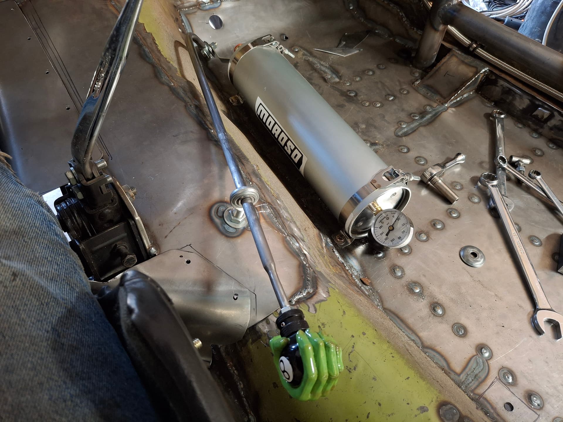
Engine Oil System
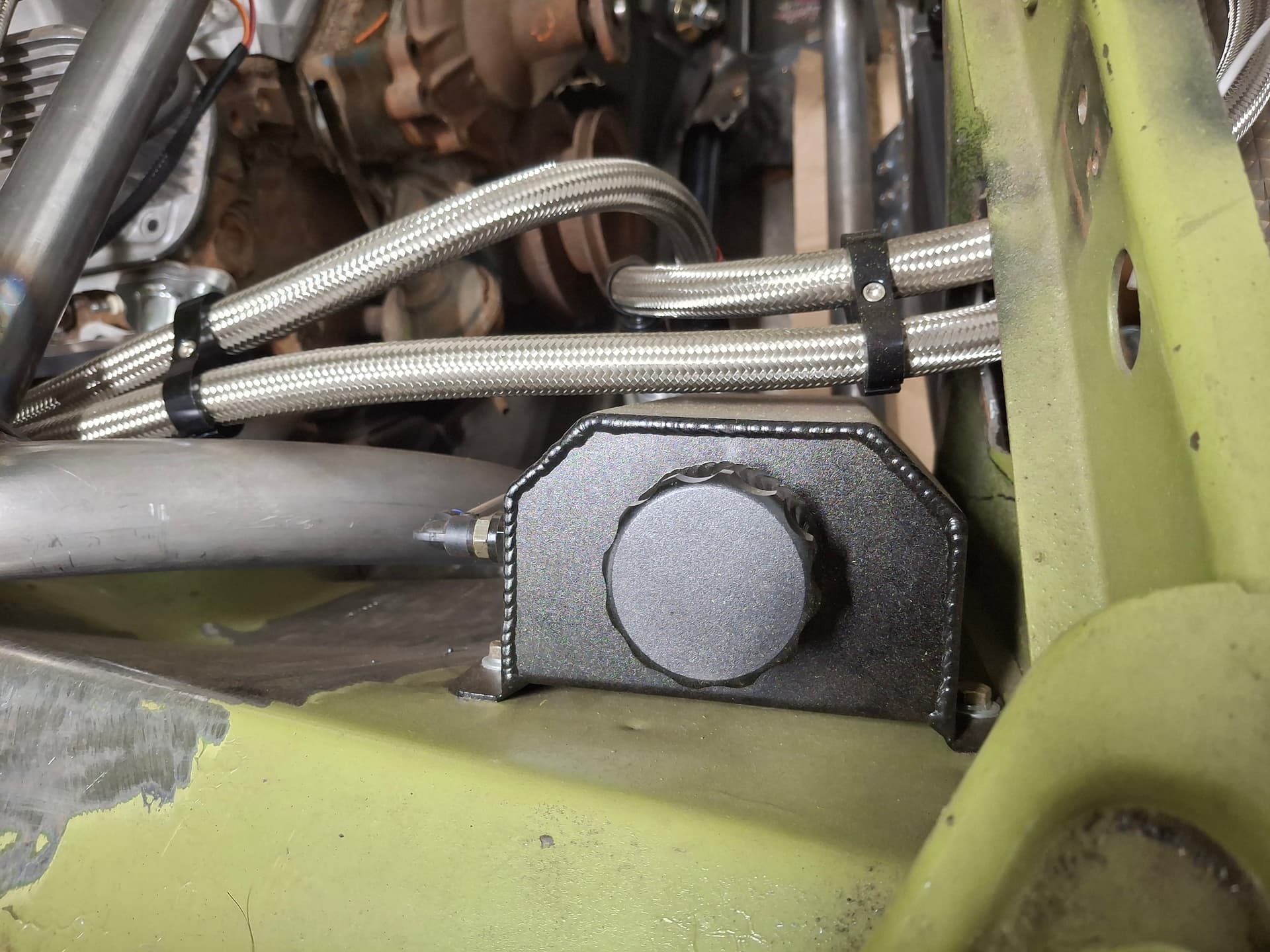
I designed the oil system to incorporate an accumulator, remote oil filter (the headers won’t allow otherwise), and oil cooler. I also designed in a low-pressure warning light directly off the block upstream the filter/cooler/accumulator and a safety switch that triggers the fuel-pump relay only when there is at least 3 psi of oil pressure or when the starter is cranking. With this safety system, the fuel pump will shut off in a wreck either if I shut off the kill switch or if the engine stops running.
For weight distribution and to limit the amount of oil hose in the driver’s compartment, I installed the accumulator in the passenger footwell. I drilled a hole through the ball-valve lever, installed a heim, and built a hollow rod for me to easily open and close the valve while buckled in. I welded a stud onto the end of the rod and tapped into my hot rod heritage with a knob appropriate for this beast.
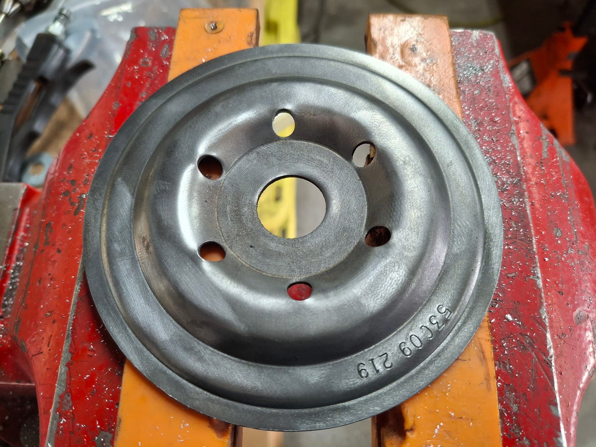
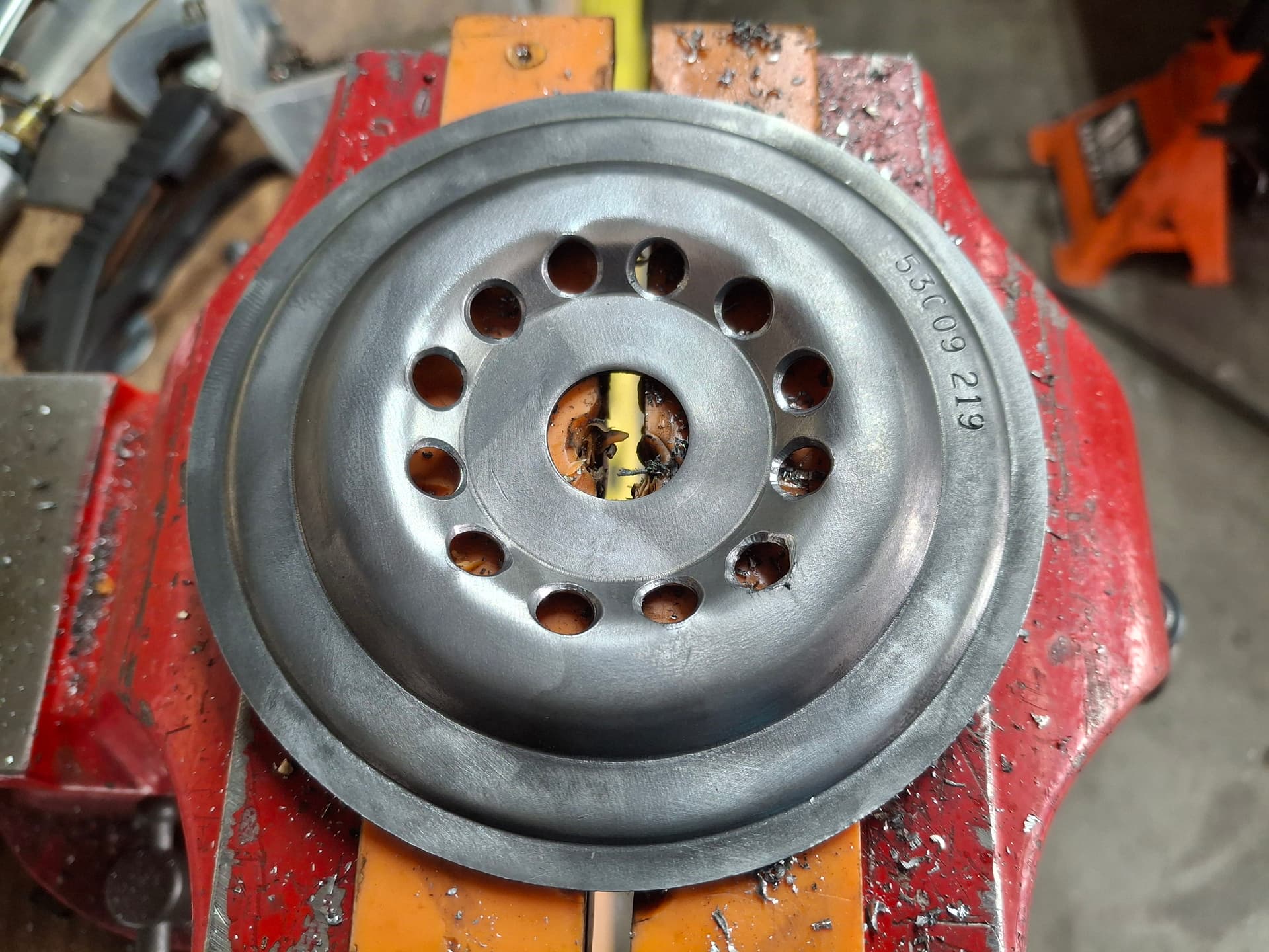
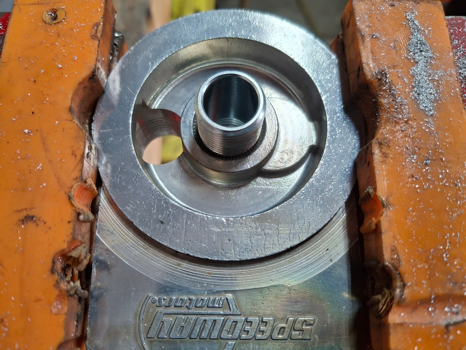
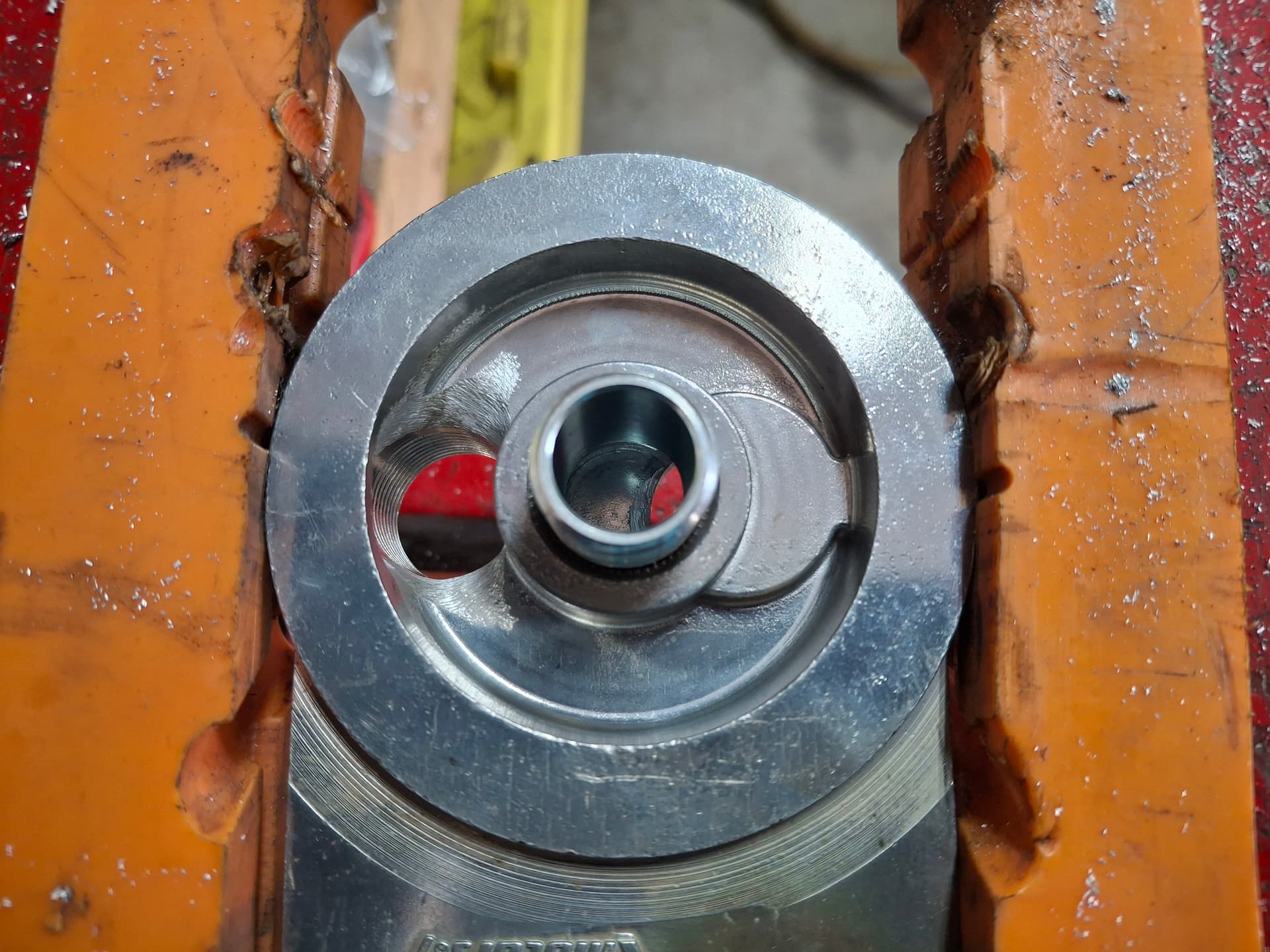
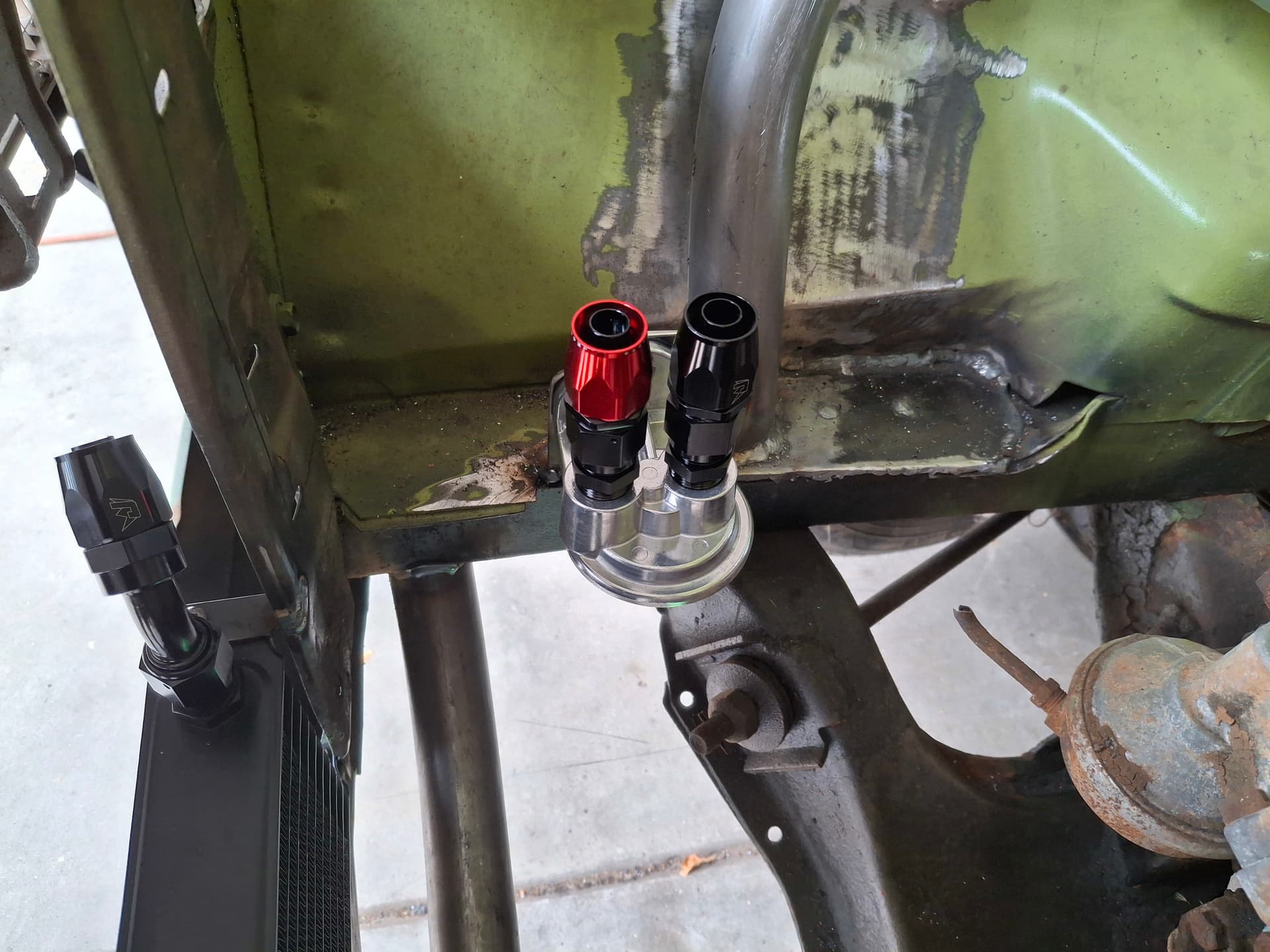
Turning my attention to the fittings and fixtures, I first modified the factory Plymouth oil filter adapter plate from a restrictive six 5/16" holes to twelve for higher volume and beveled the edges.
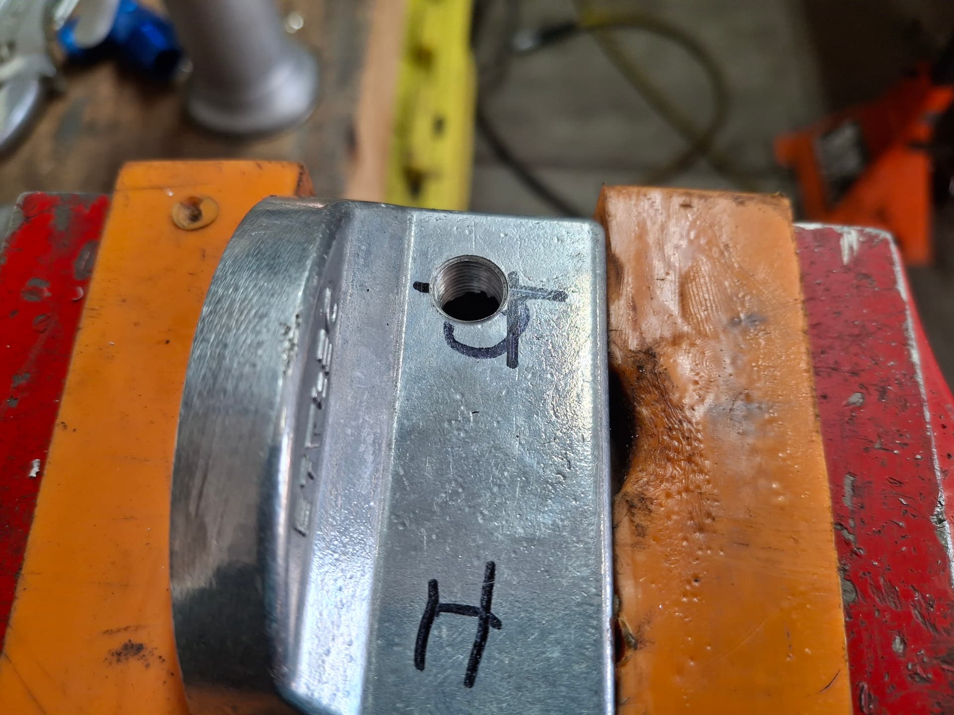
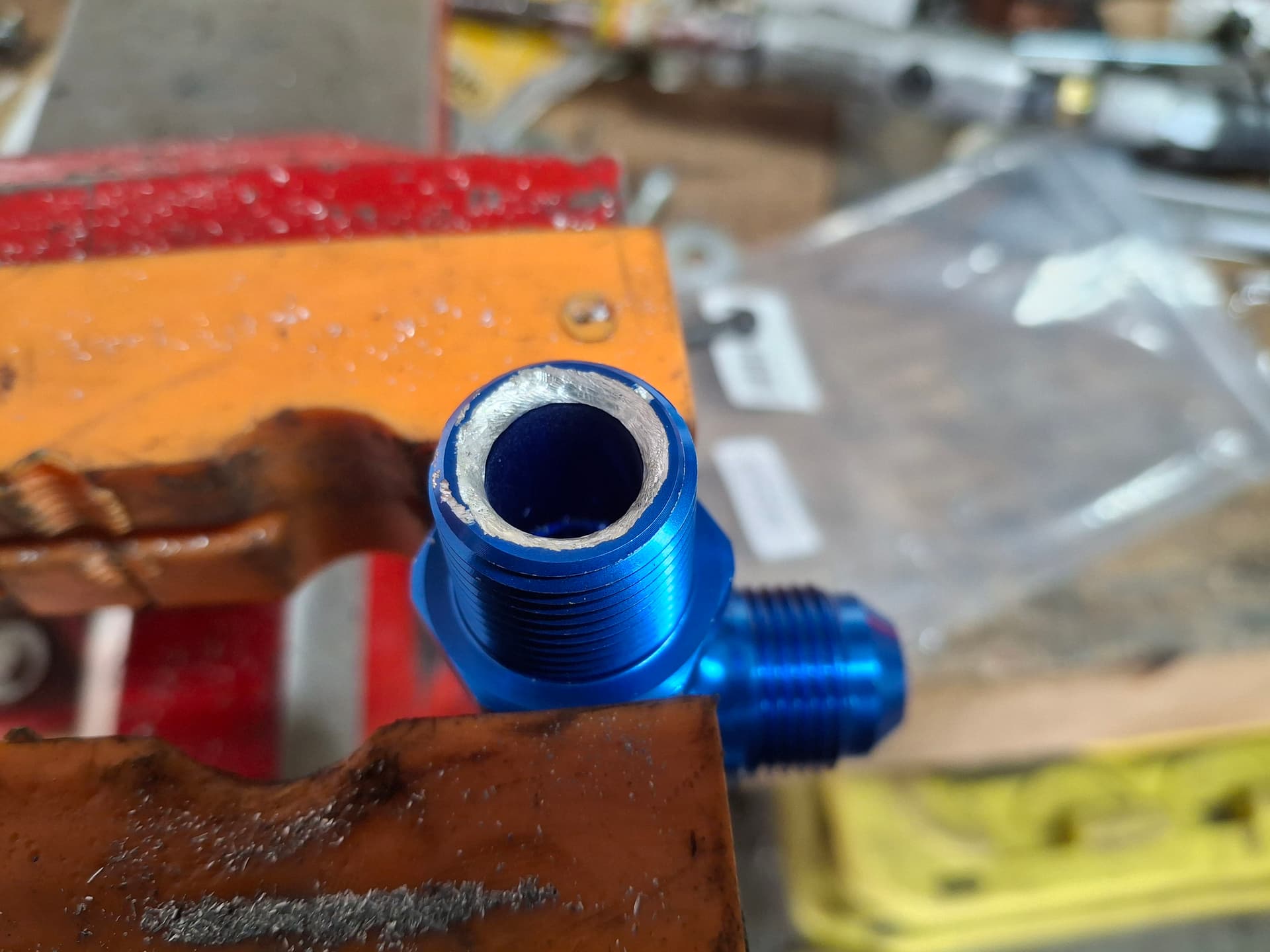
I drilled and tapped a 1/8" NPT port into the filter adapter where the low-pressure warning light switch will reside. I drilled a 1/8" NPT port into the -10 AN tee where the fuel pump safety oil-pressure switch will reside.
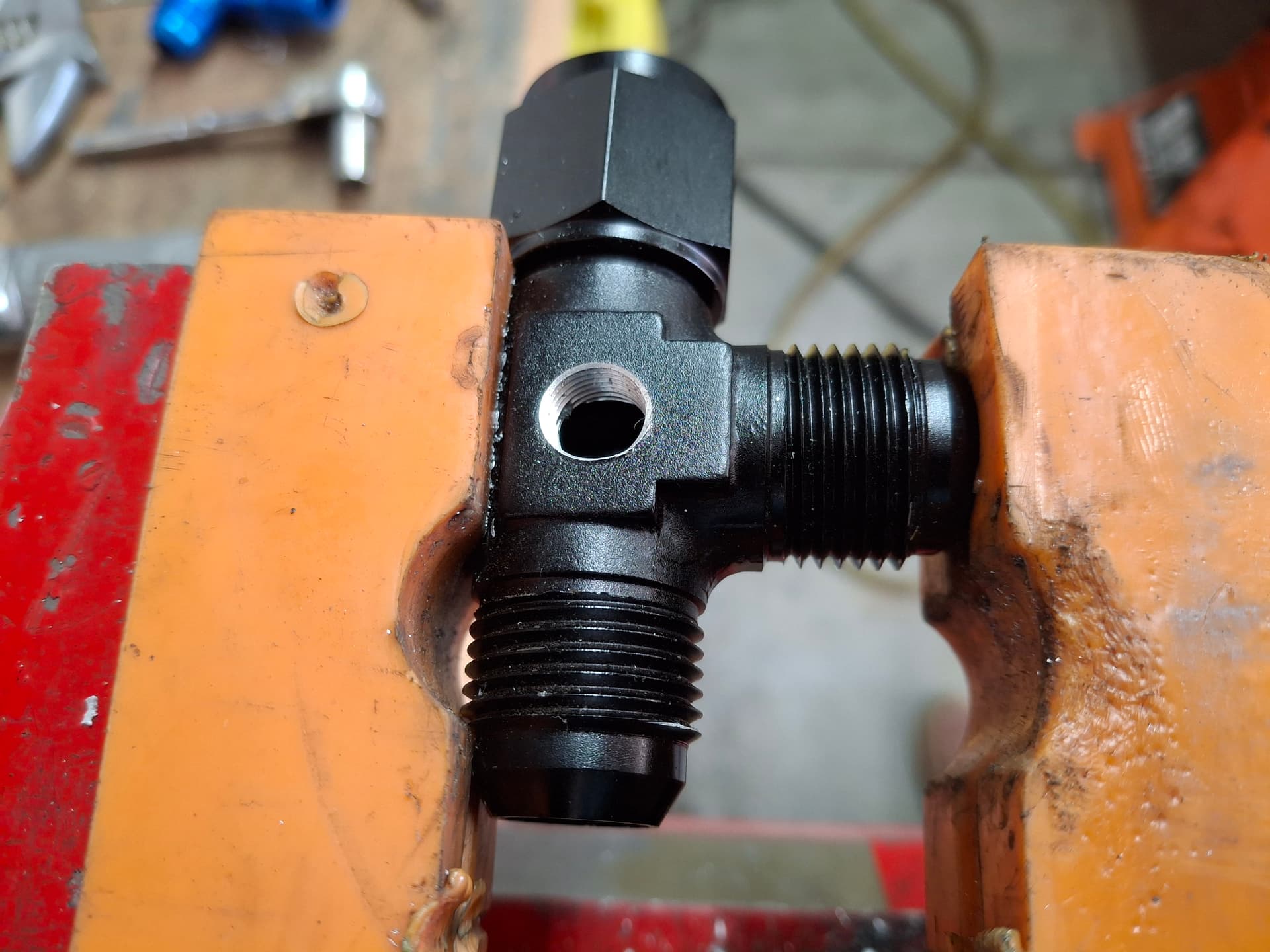
I used a die grinder with burr bits to smooth out as many sharp corners as I could reach and had enough meat to work with on the pipe-thread AN fittings, the block oil-filter adapter, and the remote oil filter adapter to promote flow and decrease turbulence.
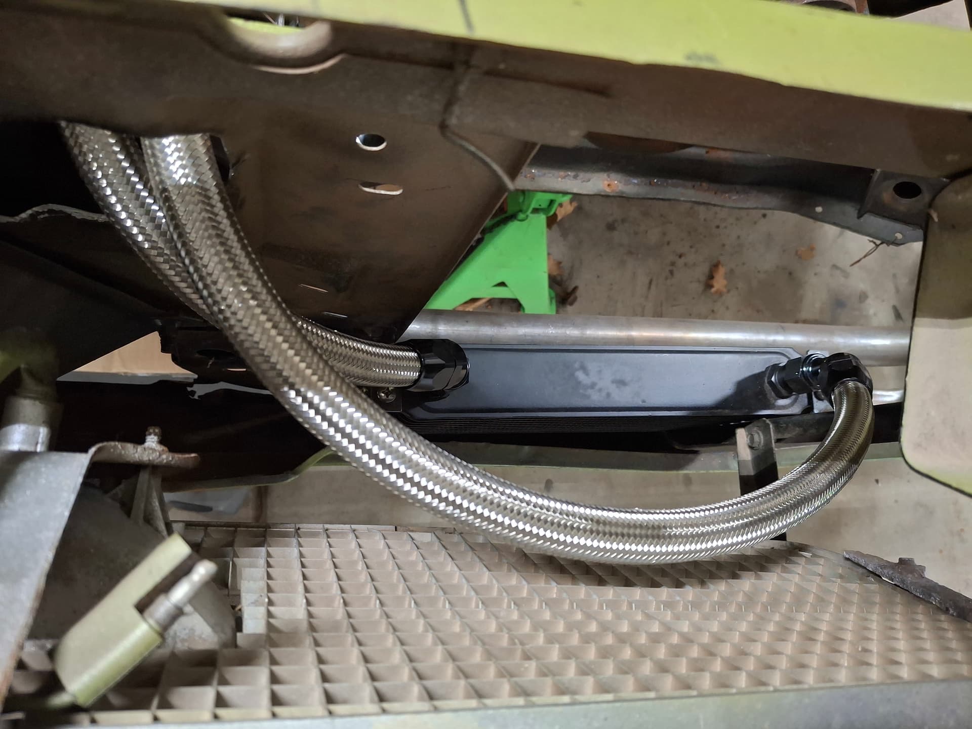
I fabricated and welded a filter mounting plate along the right frame rail where it will be easy to access. I welded mounting tabs on the radiator core support and center grille brace to secure the oil cooler. While I would not have the cooler in front of the radiator if I had my druthers, I simply don’t have another place to put it unless I upsize the hose to -14 and run very long hoses to underneath the rear seat kick-up and use an electric fan, which isn’t practical.
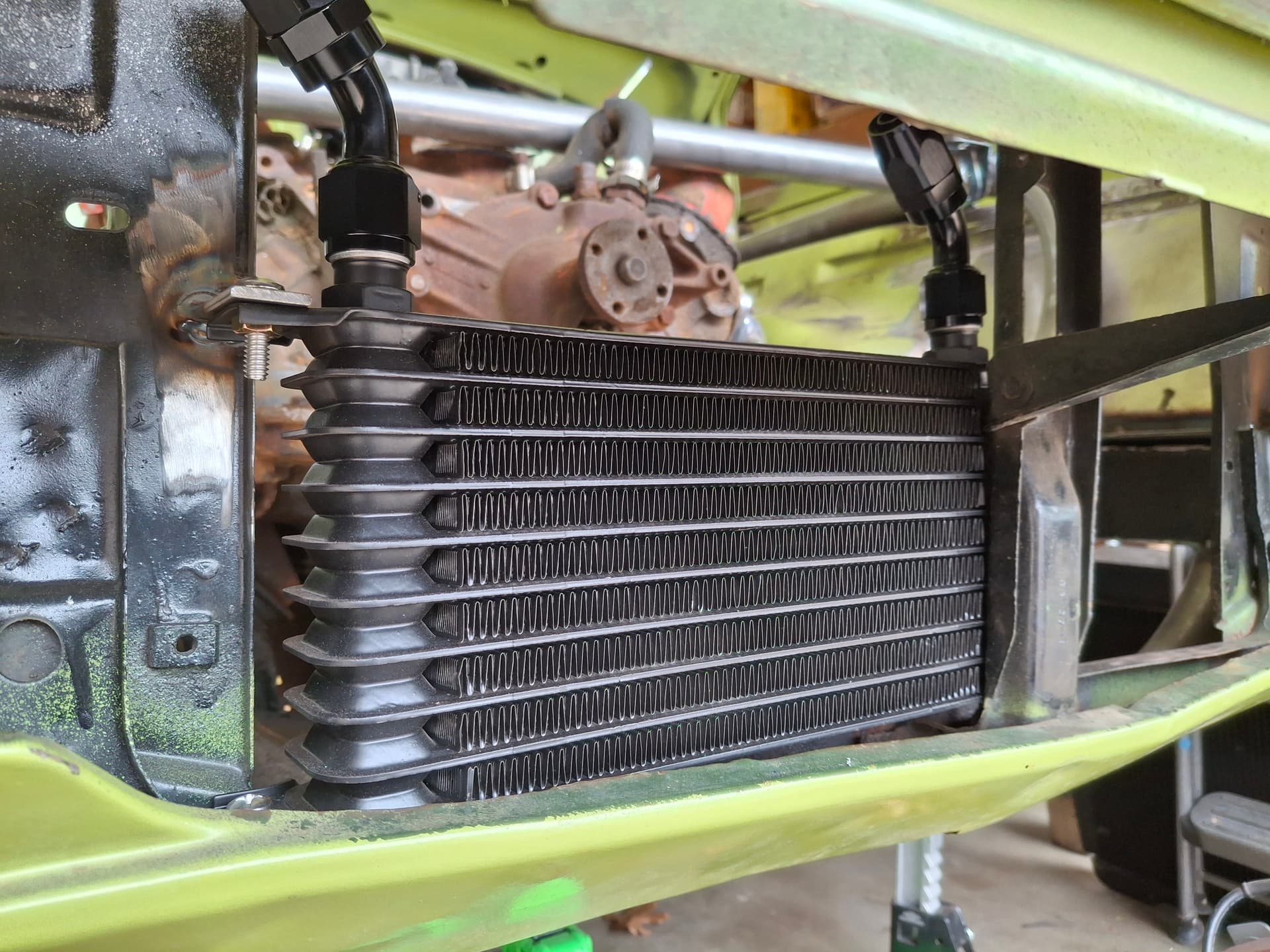
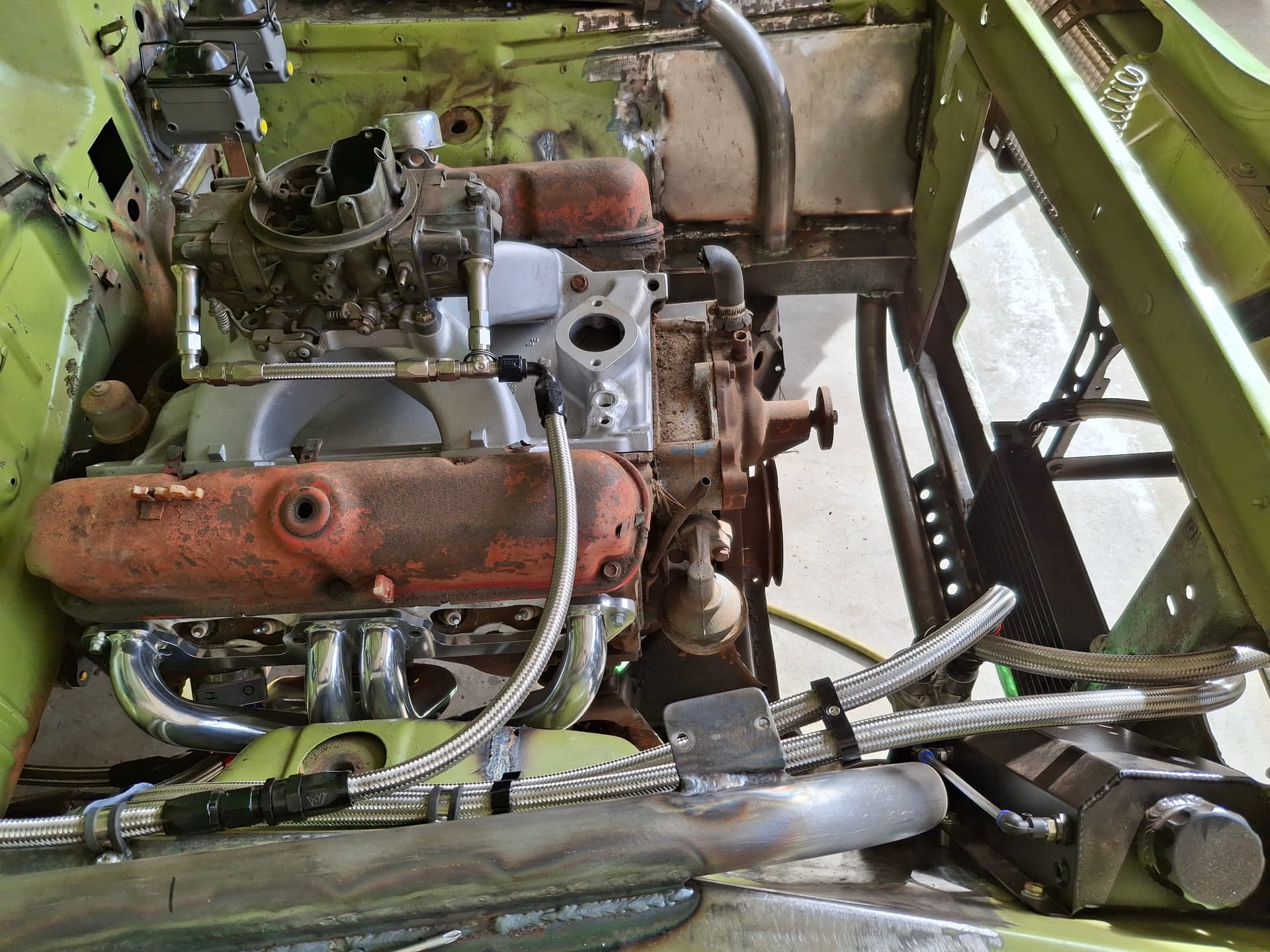
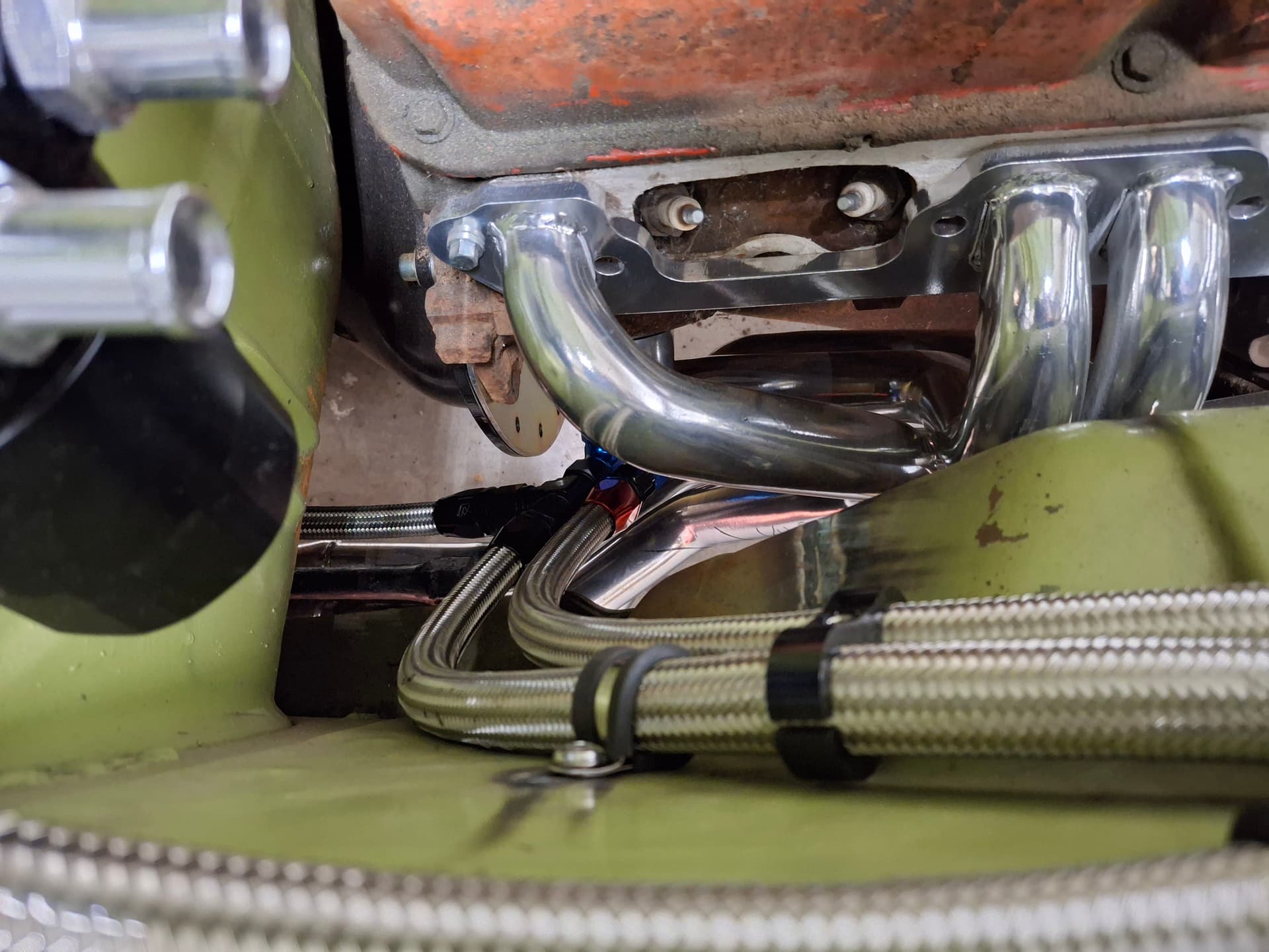
I plumbed the system with high-temp -10 braided stainless hose in the order of block outlet directly from the oil pump > adapter with oil-pressure warning light > remote oil filter > oil cooler > accumulator > fuel-pump safety switch > inlet into the block’s main oil gallery. Note that the photo perspective around the headers is deceiving. The hoses have ample clearance around the headers, although I will be wrapping them in insulation jackets and possibly building a metal heat shield to limit heat transfer as much as possible.
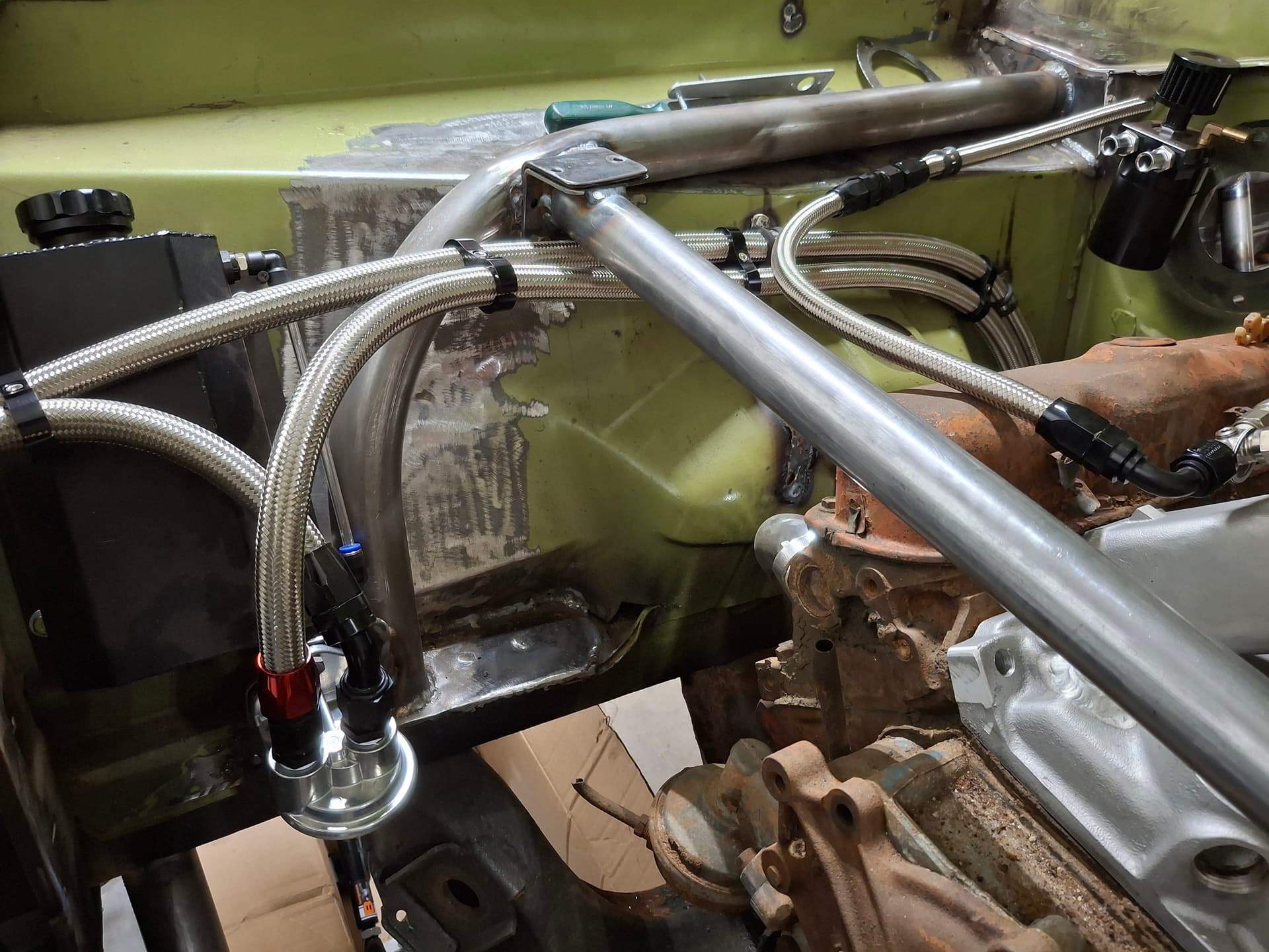
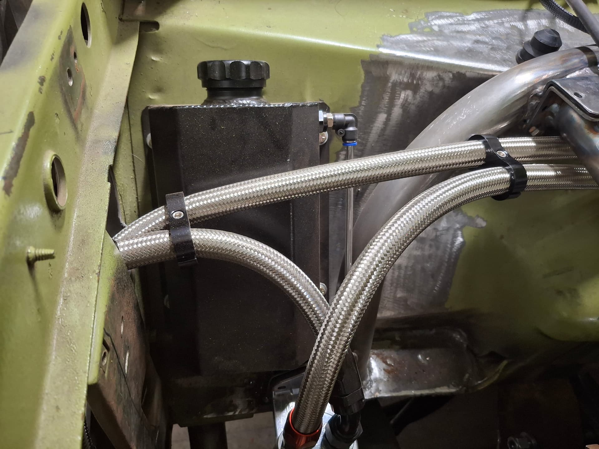
Engine Coolant Expansion Tank
I modified for fitment and installed the coolant expansion tank. Due to room restrictions, it lays flat against the angled inner fender, but I oversized the tank knowing it will hold slightly less fluid before hitting the overflow port.
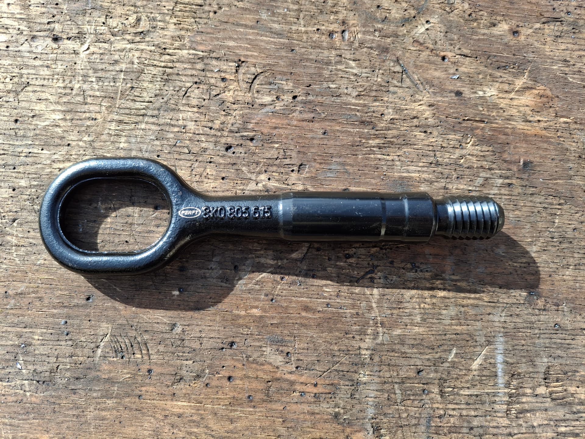
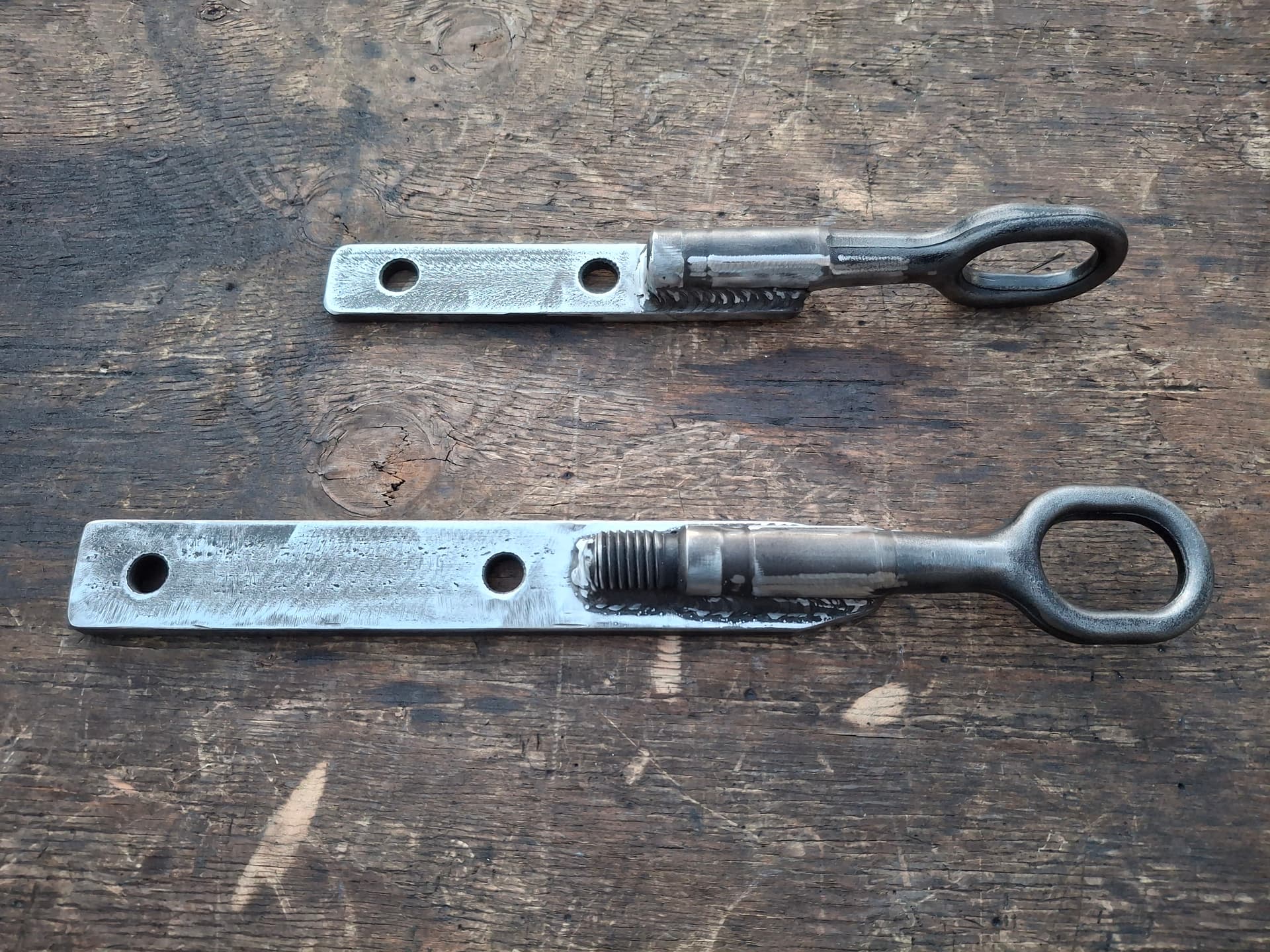
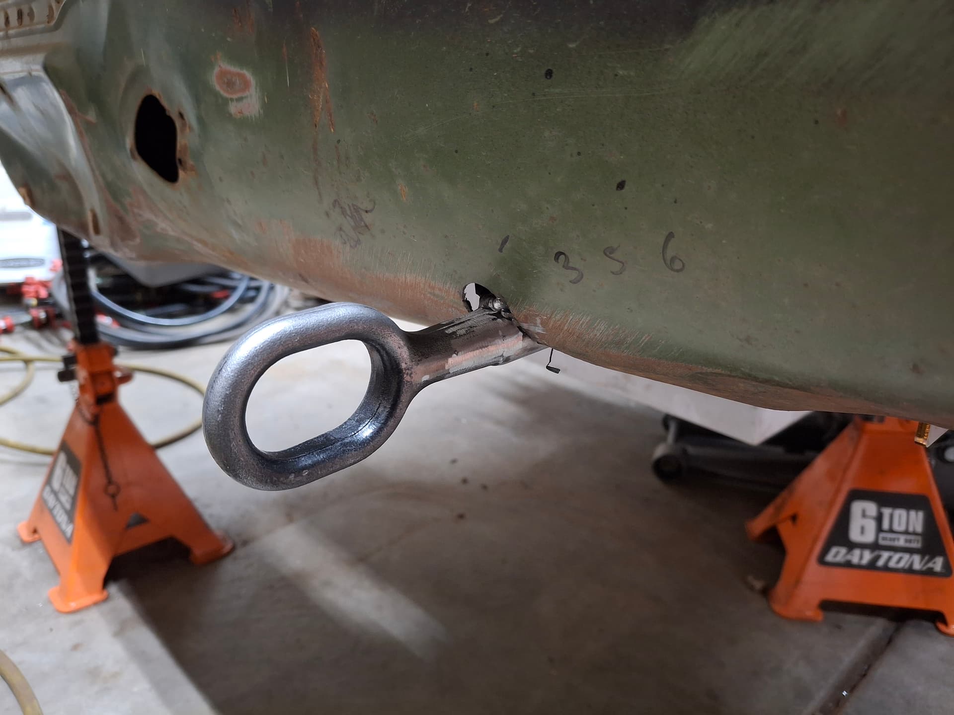
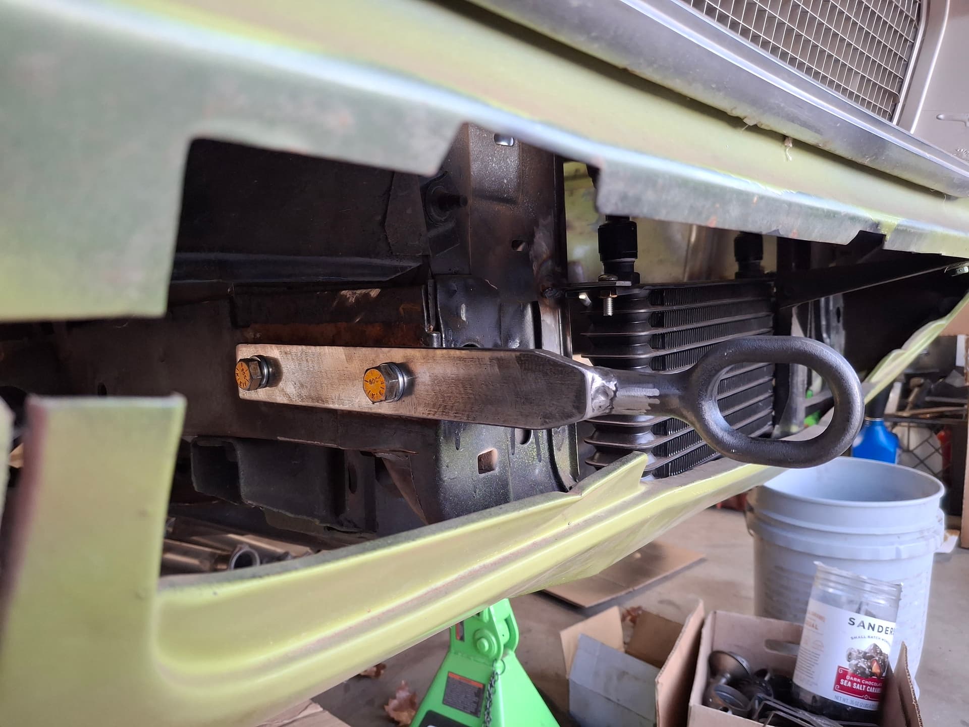
Tow Hooks
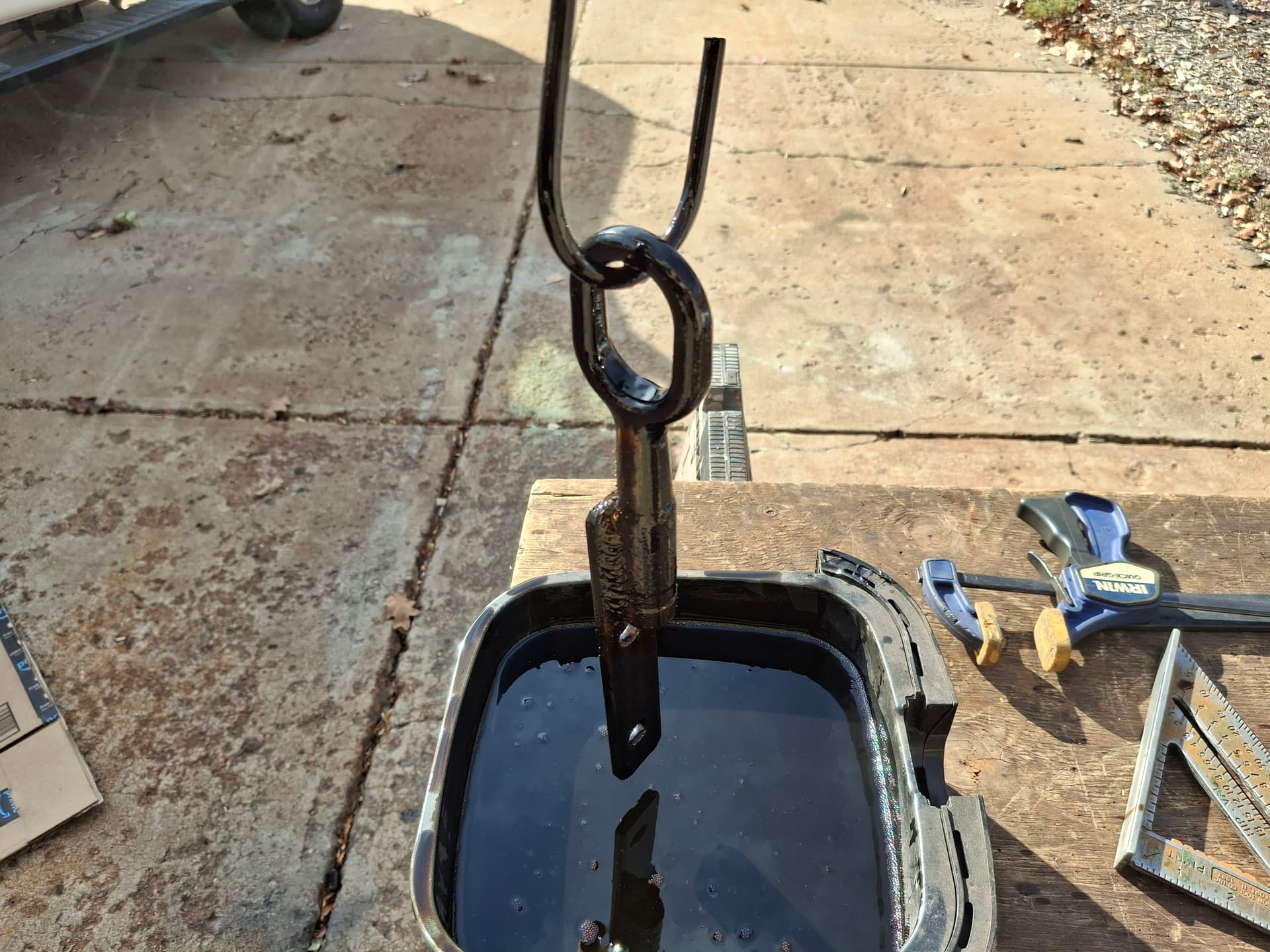
I got the idea for tow hooks after seeing a factory Audi hook at an HPR open lapping day. I obtained two aftermarket forged hooks, flattened the side a bit, and welded them to 1/4" plate brackets. I wish I had photos of me in my leather welding jacket, gloves, and helmet surrounded by smoke when I went full “Forged in Fire,” the knife-building competition TV show. Since the round hooks took multiple welding passes to bed them into the plate, I was concerned about the brackets and hooks losing their hardness. I heated the hooks-bracket assemblies to a dull orange with an oxy acetylene torch and quenched them in an container filled with used motor oil. While I’m not going to send them off for testing or anything, they appear hardened according to a before-and-after hand file test. I guess we’ll find out if I ever need to get pulled out of the gravel, which I’ll do my best to avoid.
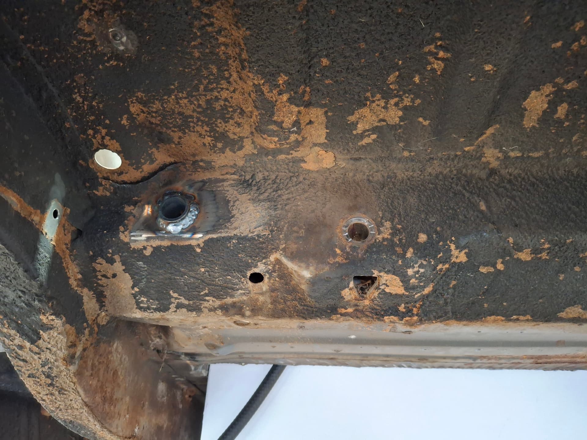
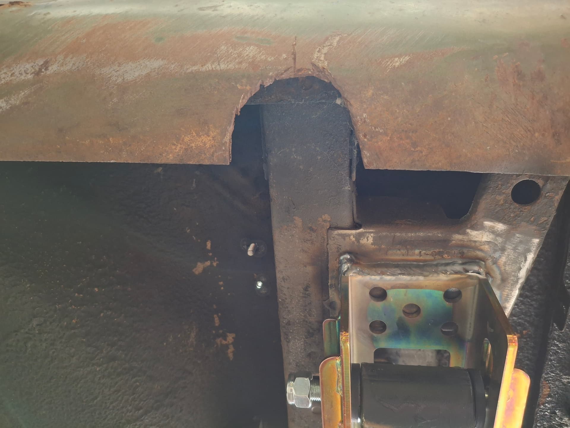
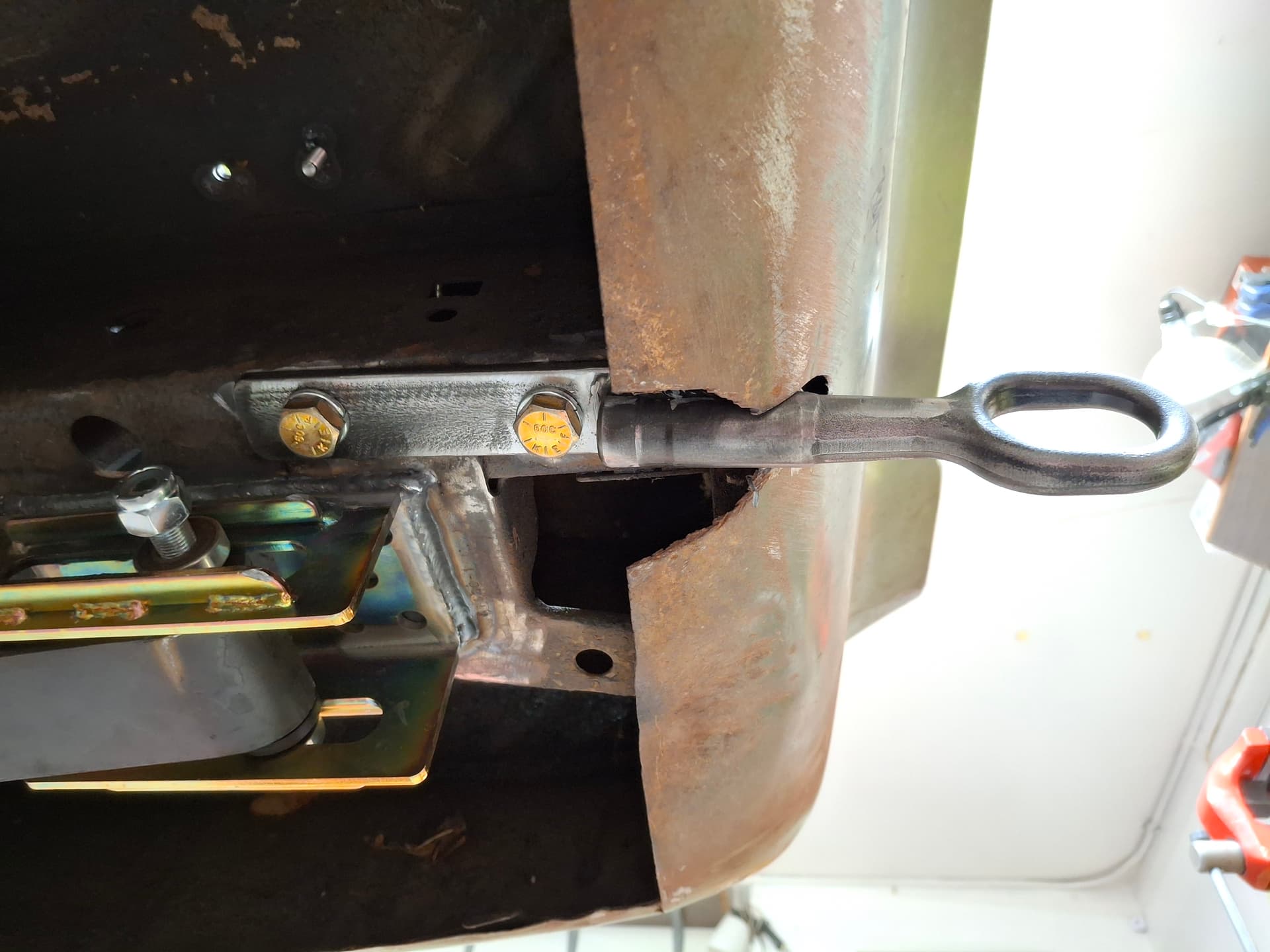
For the rear, with weight distribution in mind, I drilled and welded in threaded 1/2" bungs on the right subframe and notched the roll pan at the factory exhaust cutout. For the front, I used the factory 1/2" right bumper bracket bungs.
Post Alert Pings:
@jonUU
@Sportsracer
@Datsun78
@Bob_Alder
1 Like
Justin
Nice looking welds on the tank. Aluminum or steel construction?
I used to have tow hooks on my car but removed them as now I just have the tow operator wrap the strap around the roll bar main hoop, my car is an open cockpit car. The last time I broke on track they used the flat bed truck and I rode back to the pits on it.