Hey Tom,
I can’t take credit for the expansion tank fabrication since that’s a bought piece. It’s aluminum. You’ll see my aluminum welds at some point when I fabricate the front brake cooling scoops, and I assure you they likely won’t look as uniform as the tank. I don’t get to practice tigging aluminum much, so my chops aren’t where I wish they were. I could sit there for weeks practicing, on aluminum cards, but ain’t nobody got time for that for brake scoops ![]()
Electrical System
I’ll continue posting update photos as I begin wiring the system but wanted to share the overall plan and current progress.
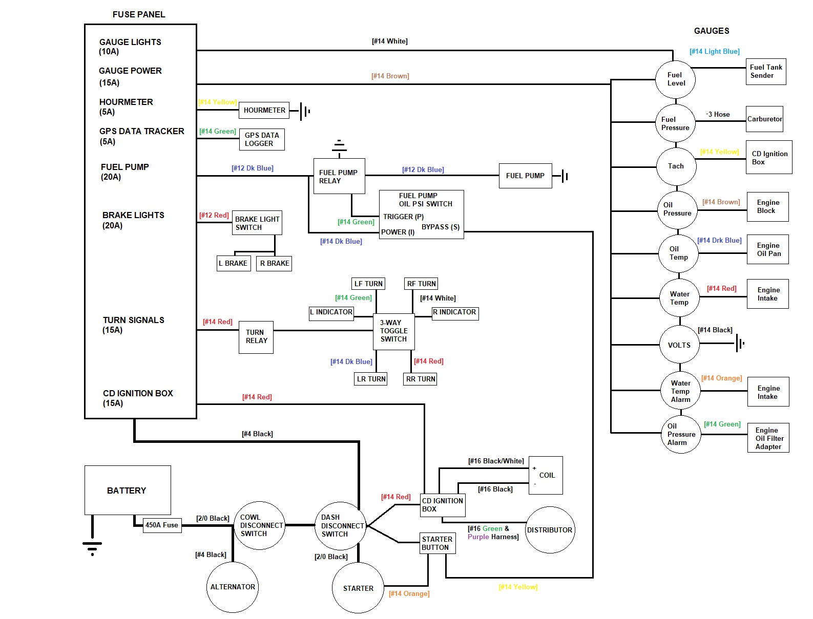
I started on the electrical system by first mapping it out. I decided to design the system to where the entire system is switched by the last master disconnect in the series, so there are no additional toggle switches to power devices except for the three-way turn signal switch.
Battery Box
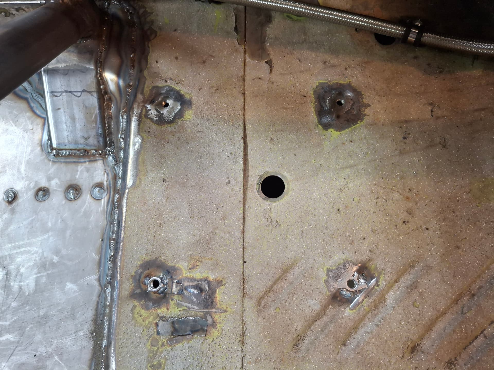
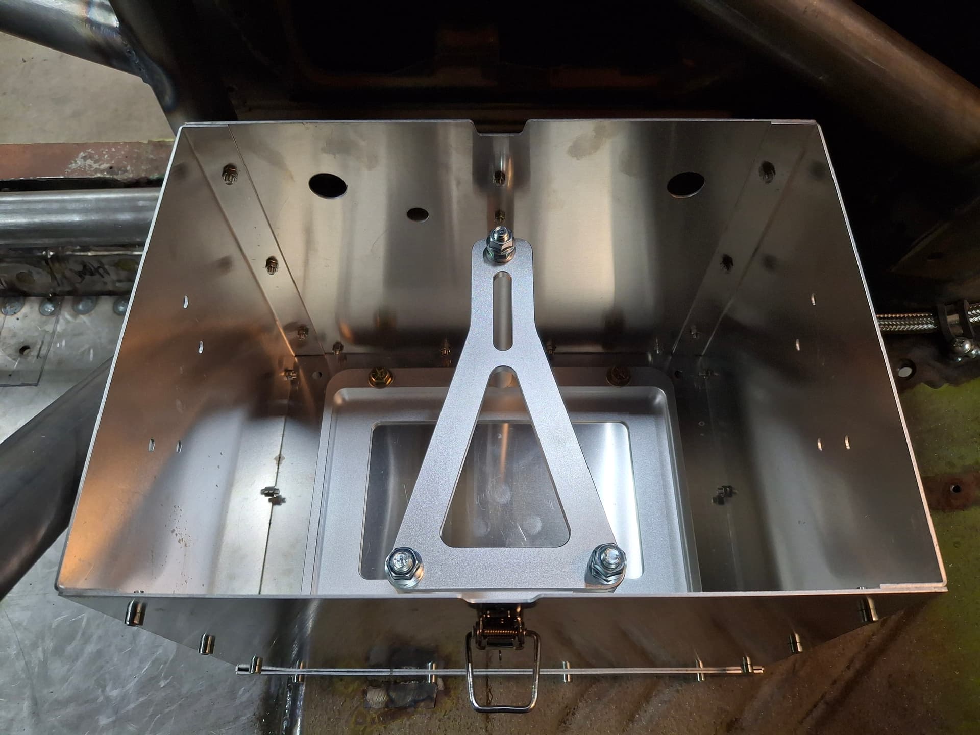
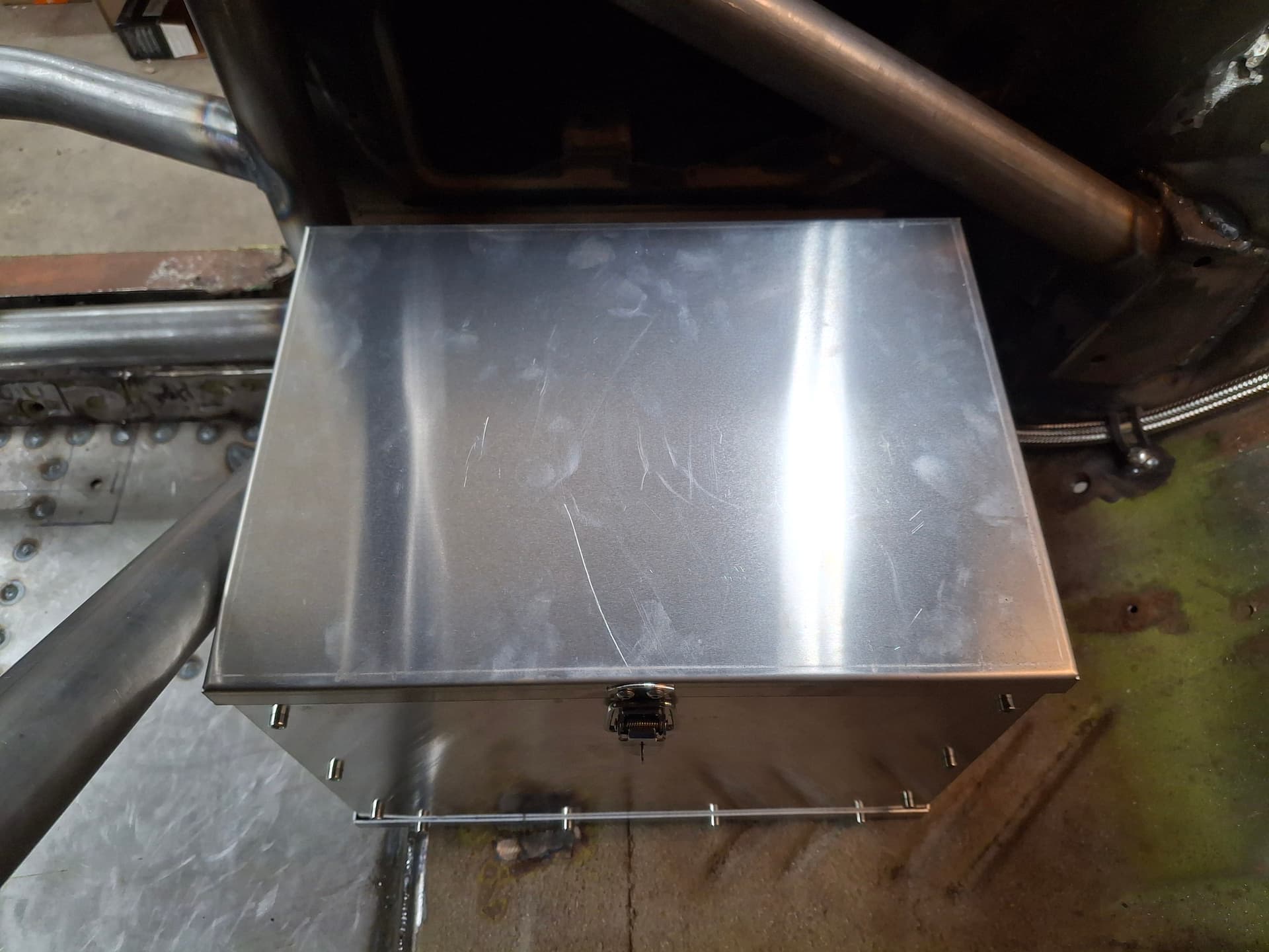
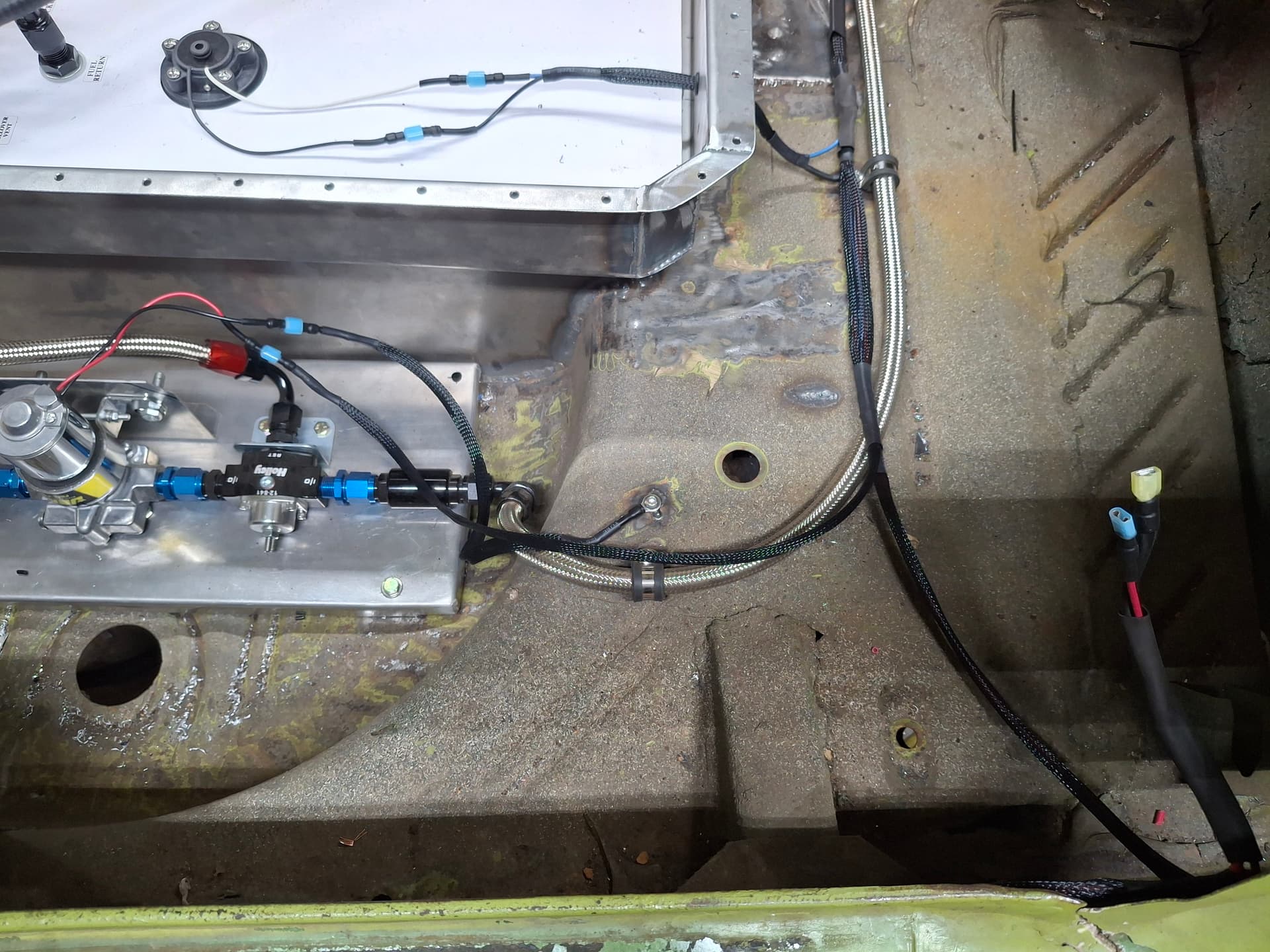
I located the battery for weight distribution on the passenger side where the rear seat used to be, leaving enough room for the onboard fire suppression tank that will either go beside it or behind the driver’s seat, depending on where the scales want the weight. I welded 3/8" nuts into the floor pan where the aluminum battery hold-down and aluminum battery box bolt directly to the floor through 3/8" thick rubber isolator pads. The battery box has two spring-loaded latches to secure the lid. The battery-box vent will run through a hole in the floor near the quarter panel.
Master Disconnect Switches
For safety, I want a redundant master disconnect system, one for each side of the car and for inside and outside. Track workers can access the first switch in the series on the right side outside the car atop the cowl and I and track workers can access the second switch on the left side on the dashboard. 2/0 stranded copper welding cable runs from the battery terminal, through a 450 amp mega fuse, up through the cowl disconnect switch, over to and through the dash disconnect switch, and down to the starter motor. The fuse panel and unfused circuits (the CD ignition box main and the starter button) are powered off the dash disconnect switch downstream side to where either of the switches will kill all power except for the 2/0 cable running from the battery to the switches. That length of cable is protected by the 450A mega fuse directly off the battery terminal in the event of a short.
Another security consideration is that I want a keyed master disconnect switch on the dash since I will be taking the car to cruises/shows and don’t want anyone to be able to power up the system with a flick of a lever. The most common keyed master disconnect is an FIA-style plastic key, which I don’t like because they can become brittle and break and RMVR General Rules don’t allow, although I see many cars running them. It took digging, but I found a 180A continuous disconnect switch with a steel key, American Autowire 500720. The dash gets this switch, and the cowl gets a traditional metal fixed-lever switch.
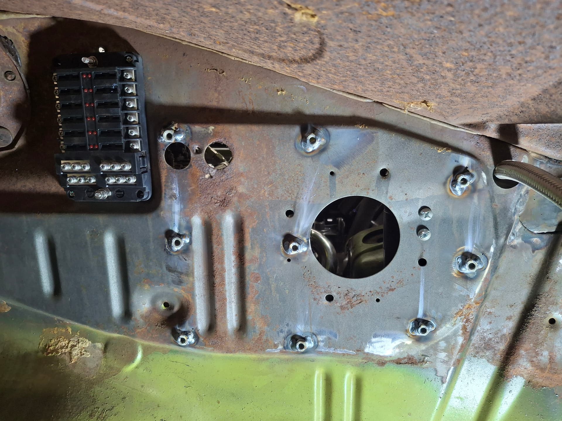
Fuse Panel
The ATO/ATC fuse panel is powered off the dash disconnect switch using #4 copper welding cable. For weight and clearance considerations, I placed the panel under the dash on the right side. The panel has an incorporated grounding bus bar, and it gets connected to the body via piece of #4 welding cable. The engine will get a 2/0 welding cable ground to the front frame rail, and the battery will get a 2/0 ground to the mid-section frame rail. All device grounds except for the fuel pump in the trunk and alternator will go back to this fuse panel bus bar to centralize the ground.
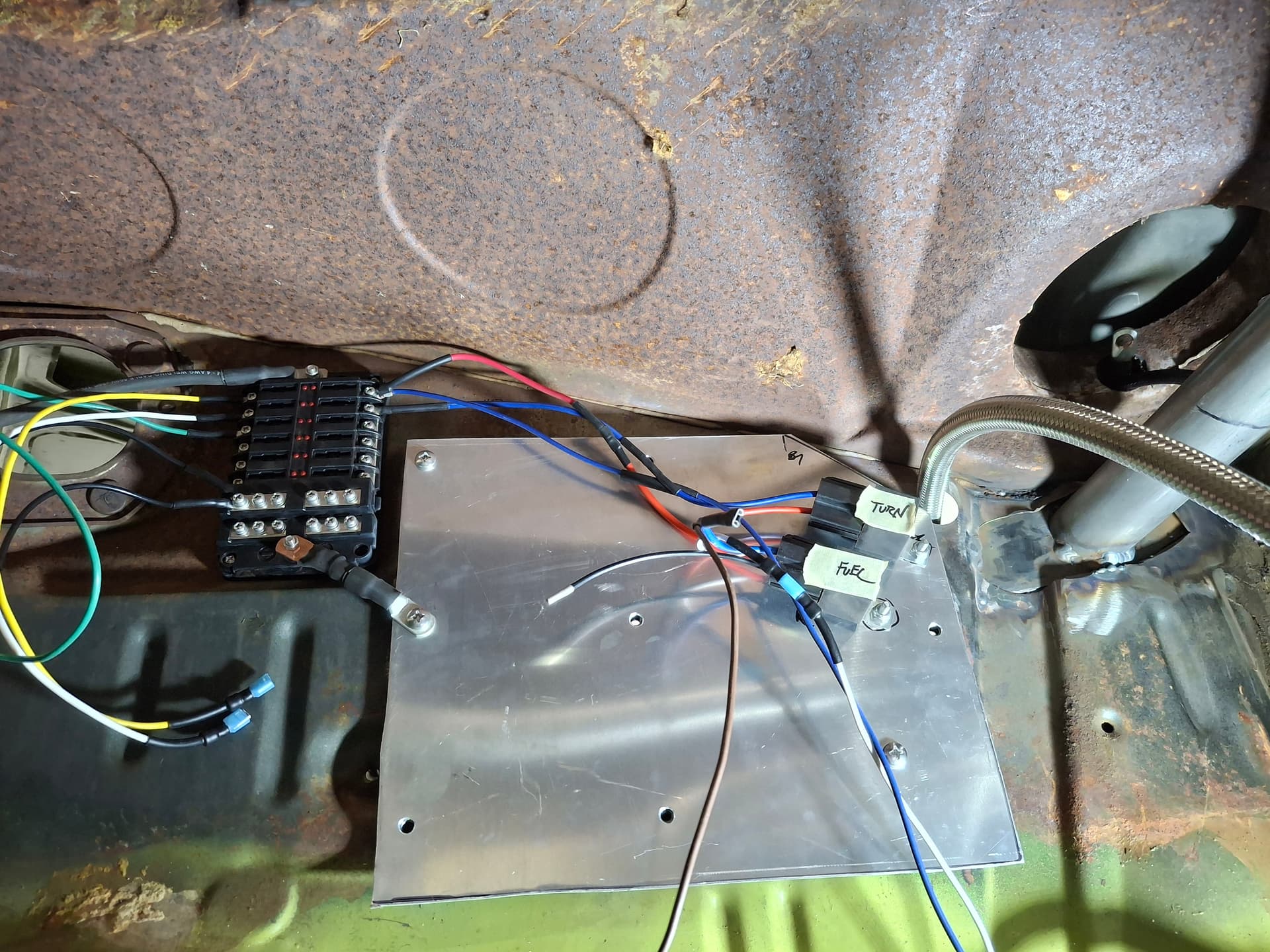
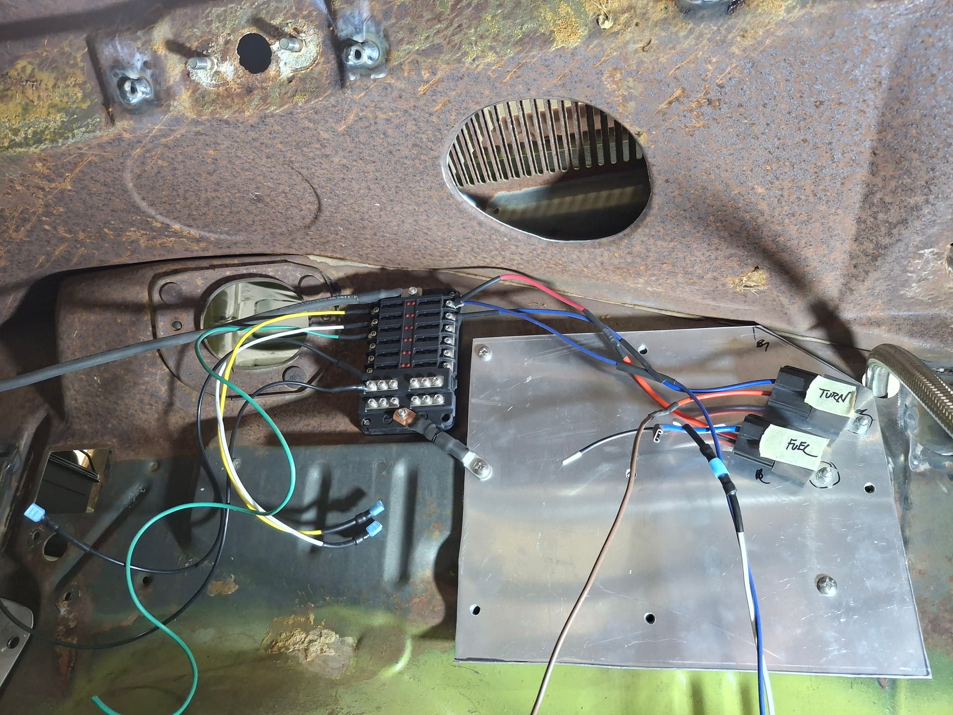
Ignition and Relay Panel
Adjacent the fuse panel, I welded stand-off nuts to the firewall and secured an aluminum sheet where the CD ignition box, coil, fuel-pump relay, and turn signal flasher relay will attach. At a later stage, I will weld up the factory heater blower motor and heater core holes in the firewall for fire protection and to keep engine-compartment heat off the aluminum mounting panel. Directly above this panel is the floor for the fresh-air intake duct. The factory setup has two 6" round holes in the floor of the duct, one on the far left for the fresh air footwell door and one on the far right for the heater box. I cut a new 5" hole in the floor of the duct directly above the ignition panel where the CD box and coil will be so fresh air will blow directly down across/through them for cooling.
Alternator
I am running a 90A one-wire Chrysler alternator, although I only need a 60 AMP but no one makes a one-wire smaller than 90A. The #4 welding cable will run from it to the battery-side of the cowl disconnect switch. In this configuration, the alternator will both charge the battery and power the system, but either of the two disconnect switches will stop the alternator from continuing to power the ignition system.
Fuel Pump
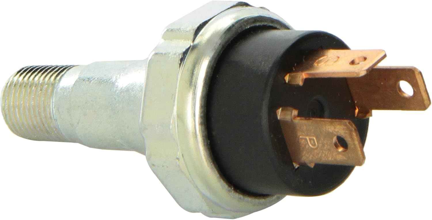
For safety, I wanted to give the best chance that the fuel pump would automatically shut off in the event the engine were to stall, fuel hoses were compromised, and I was unable to manually operate the dash disconnect switch. The two options I know of are a older-style OEM ball-seat inertia switch and a GM Vega oil-pressure switch. While an older OEM inertia switch is the easier route for wiring, they had issues on street cars with false triggers that required them to be reset, which is why manufacturers eventually abandoned the design and now use the ECU and sensors to calculate and trigger the inertia switch. I was concerned a ball-seat inertia switch would be plagued with false triggers in a race car prone to heavy braking and hard cornering, so I went with a Vega oil-pressure system.
The Vega switch works off oil pressure, which I tapped into at the accumulator’s -10 AN tee in the oil cooler system. I decided to use a relay rather than sending the fuel-pump current through the switch. The switch has terminals “I,” “P,” and “S.” “I” and “P” are normally open and close only when there is 3 or more oil psi present. “P” and “S” are normally closed. Fused power runs to “I” whenever the disconnect switch is turned on, but the pump relay receives no signal since there is no oil pressure. A signal/trigger wire runs from “P” to the fuel-pump relay. A bypass wire runs from “S” to the starter button. With the disconnect switch on and once the starter button is pressed/closed, current flows through “S” to “P” to the relay, powering the fuel pump during cranking. Once the engine fires and the starter button is lifted/opened, the engine oil pressure closes the “I” to “P” circuit, signaling the relay to close and powering the fuel pump. Should the engine stall for whatever reason, the pump automatically shuts off.
Brake and Turn Signal Lights
The brake and turn signal lights presented an obstacle because I am not running a factory steering column and turn-signal switch. While I only need brake lights for the track, I need turn signals for the street. I decided on using a three-way toggle switch and small green LED indicator lights, one for left and one for right. Rather than coming up with a switch system to utilize the brake-light circuit for the rear turn signals, I decided on a workaround. Each taillight has one dual-filament bulb. I will use the high-watt filament for the brake light circuit and the low-watt filament for the turn-signal circuit since I’m not using running lights/headlights. This plan should work fine when using the turn signals without the brakes applied, which I think is the most critical part for signaling lane changes, but it will look odd when signaling at a stop while braking since the brake light will remain on while another dimmer light is flashing. I’ll see what it looks like when testing, and may need to try and find a bulb with two high-watt filaments or add an additional high-watt bulb into the taillight housing. Absolute worst case, use my hand signals. ![]()
Gauges and Warning Lights
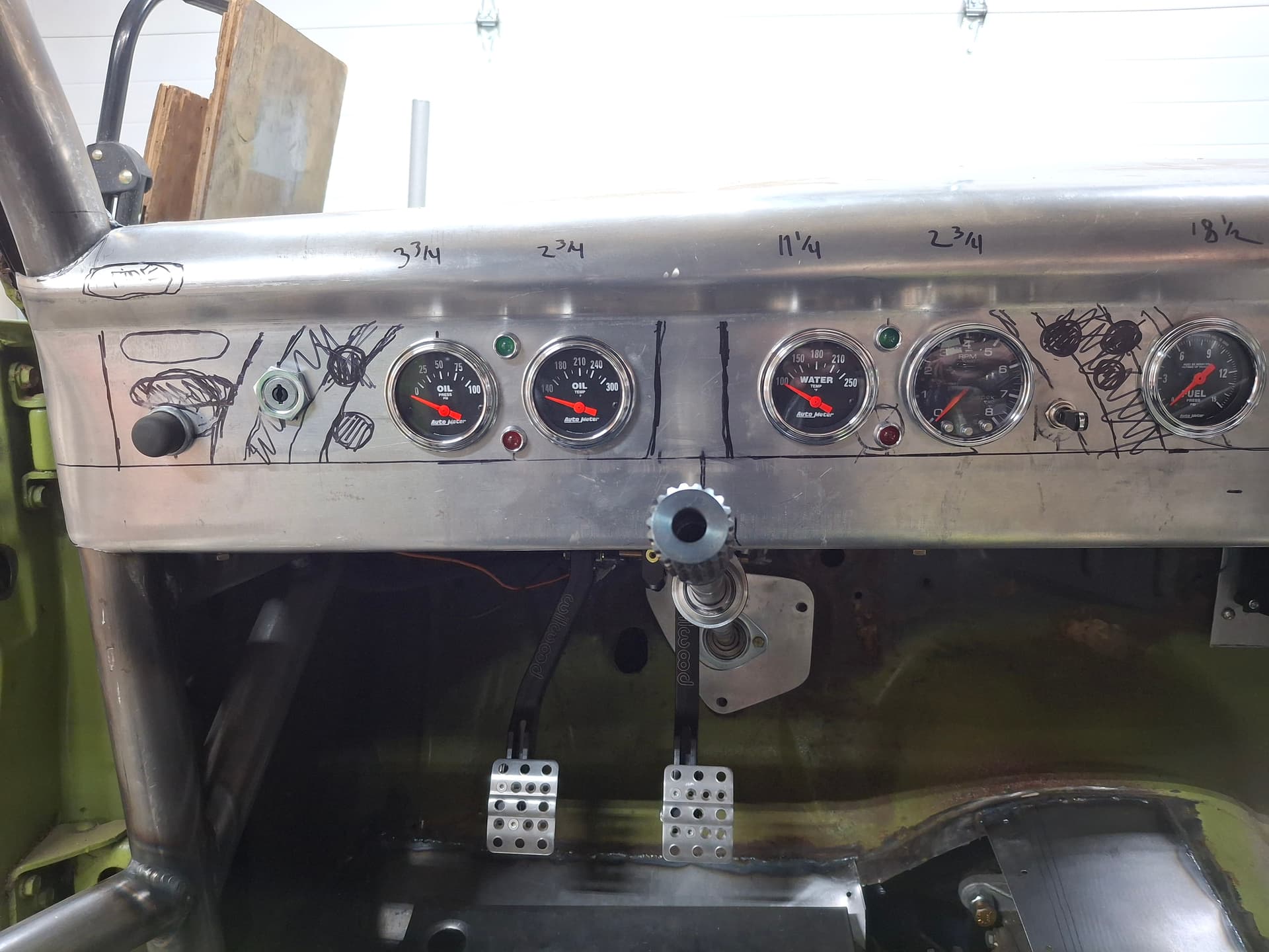
I’ll have a full complement of electronic gauges including tachometer with integrated shift light, oil pressure, oil temperature, water temperature, volts, fuel level, and a mechanical fuel pressure gauge used during testing/diagnostics. Along with the gauges, I will have red LED warning lights that illuminate when the dash disconnect is on to remind me the switch is on and that illuminate if oil pressure drops below 12 psi or water temperature climbs above 230°F.
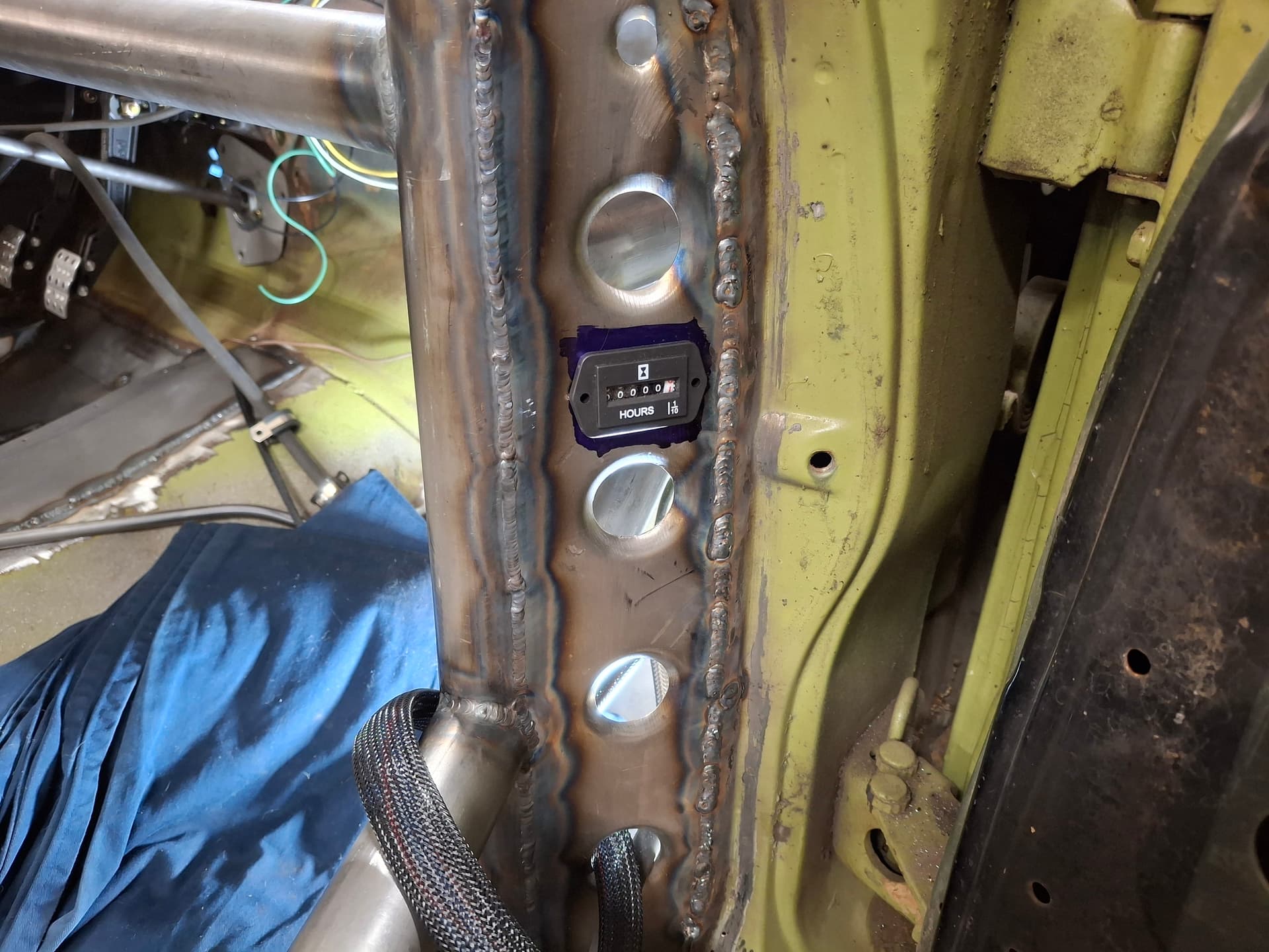
Hourmeter
I assume this device is an oddity amongst race cars, but without a speedometer with odometer, I have no way of quantitatively tracking engine run time. The easiest method I came up with was to incorporate an inexpensive hourmeter that will run whenever the fuse panel is powered. The meter will give me approximate-enough data on engine run time to help me schedule routine maintenance and track when potential problems start/stop.
Now it’s a matter of getting to work on the system.
Post Alert Pings:
@jonUU
@Sportsracer
@Datsun78
@Bob_Alder
Justin
Try this:
It’s wireless so it will require a battery change occasionally but maybe a little more accurate
Tom
1 Like
You’ve drawn up a nice schematic for your wiring Justin. I’ve been meaning to do a full rewire of my car for several years now, but something else (engine) always seems to take priority over the winter. Thanks for continuing to post your progress.
Tom @Sportsracer, thanks for the hourmeter line. I already purchased a hardwired one, but that vibration-activated unit is slick and will be my next experiment should the one I got not work out.
Jon @jonUU, yes, I should build great big hands that fling out the side of the car used both for point-by and turn signals ![]() In all seriousness, I considered some additional 1" round LED lights cut into the rear roll pan for the turn signals if my plan doesn’t work. When (not if) you sort the engine gremlin, I’d be happy to lend a hand with wiring the car.
In all seriousness, I considered some additional 1" round LED lights cut into the rear roll pan for the turn signals if my plan doesn’t work. When (not if) you sort the engine gremlin, I’d be happy to lend a hand with wiring the car.
Jon and Tom, I appreciate both of your continued interest in the build, which helps keep me going on those now too-frequent cold evenings because “What would Jon and Tom think if I had nothing more to post?”
Wiring the System
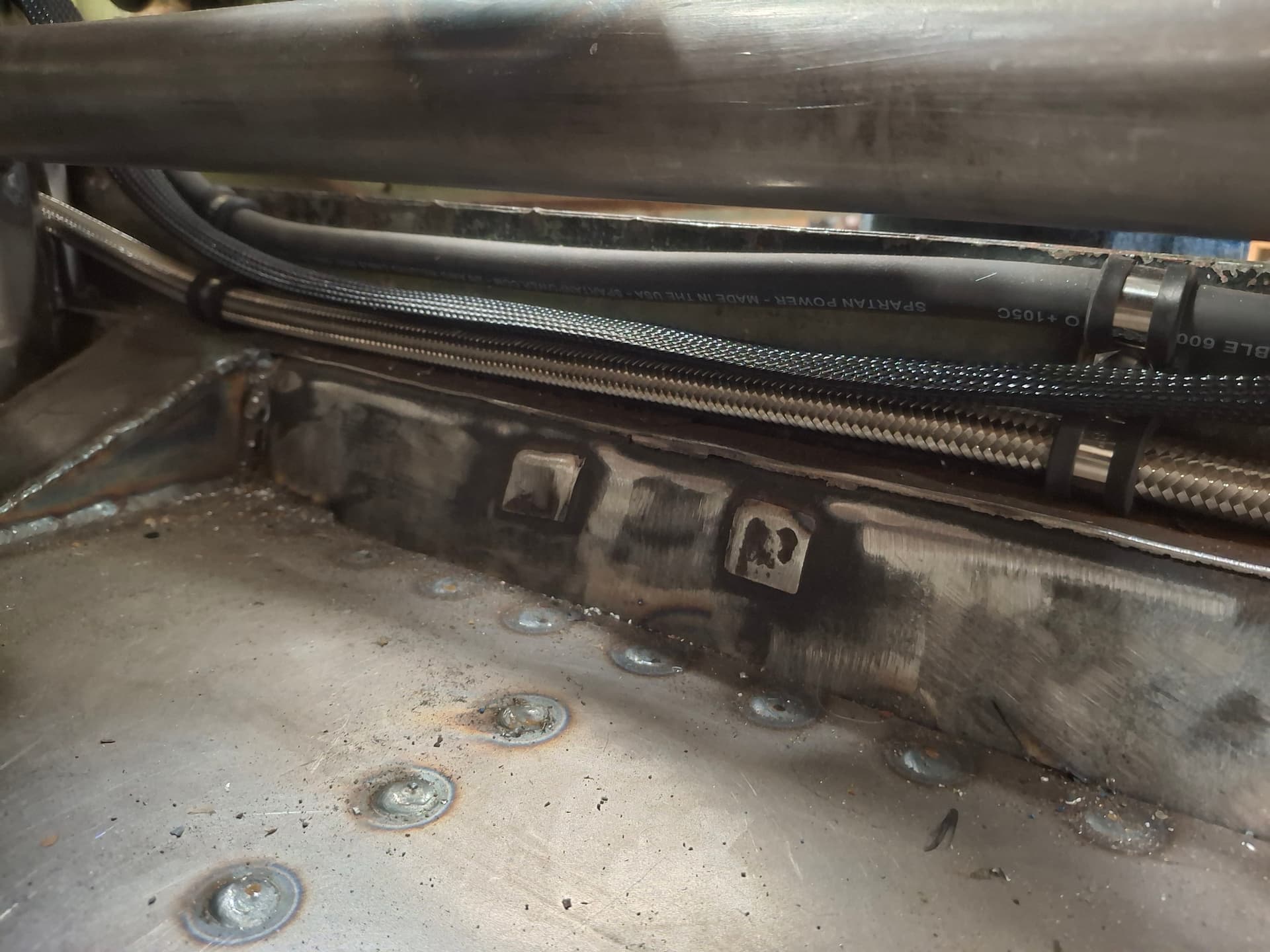
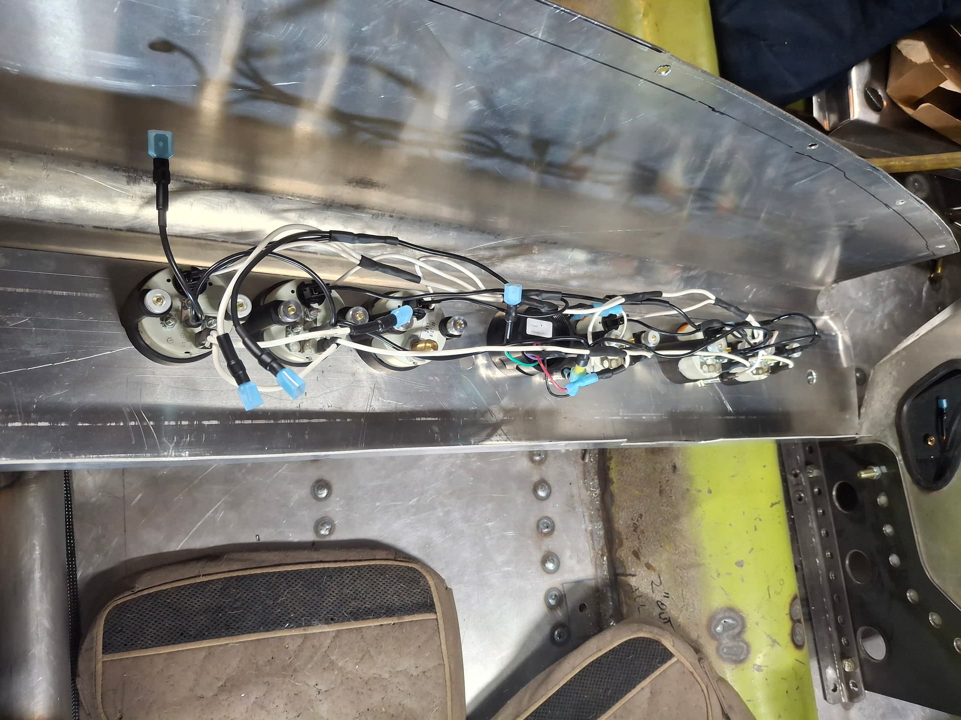
I’ve been burning the midnight oil on the wiring and have all the circuits run and only need to finish the ends at the starter motor, alternator, and battery once I have the parts purchased and installed (the wires are run wild for now), install grommets/edge protection through sheet metal holes, and install a few more Adel clamps and zip ties during final installation.
I tried to keep the main cables and bundles separated for heat and securely fastened to reduce work hardening from vibration.
The battery cables and rear wires run along the right rocker panel to either the battery or to the trunk.
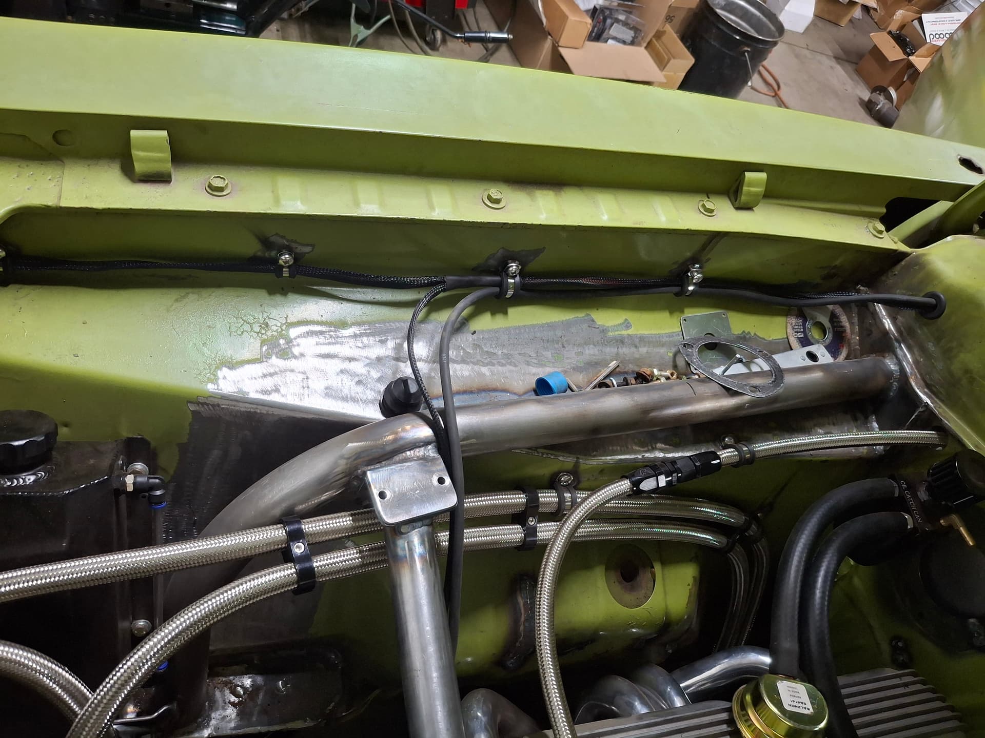
The engine-compartment harness runs along the right inner fender to the coolant sensors, alternator, and front turn signals, and another harness runs along the oil accumulator hose to the oil sensors.
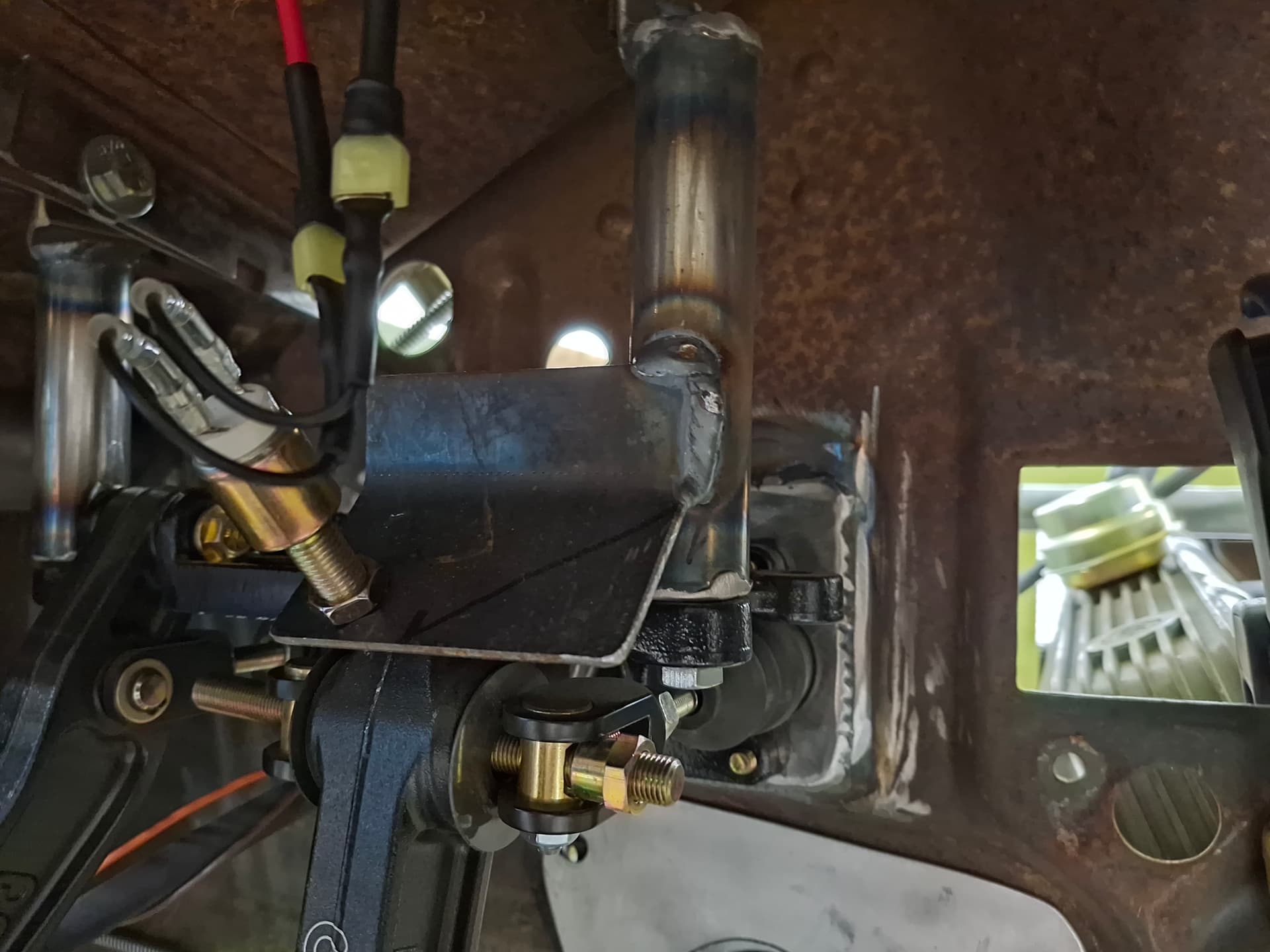
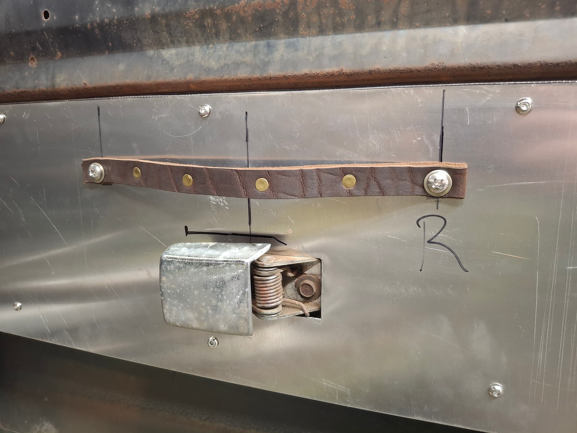
Brake Light Switch
I went with a plunger-type brake-light switch versus a hydraulic switch. I welded a plate onto the pedal assembly mounting bracket, drilled and tapped a hole, and threaded the switch into it.
Hourmeter
I cut a rectangular hole in the right door jamb gusset for the hourmeter where it’s out of the way but easily accessible.
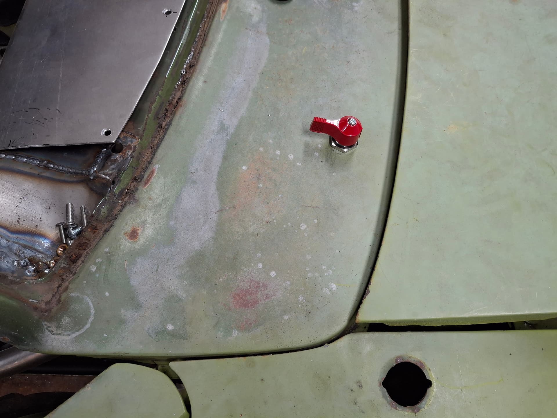
Master Disconnect Switches
I located the first master disconnect in the series atop the cowl for ease of access from outside the car. Once I purchase the fire-suppression system, a pull handle will also go in this location. The other master disconnect switch uses a metal key and is located on the left of the dash where another fire pull handle will be located.
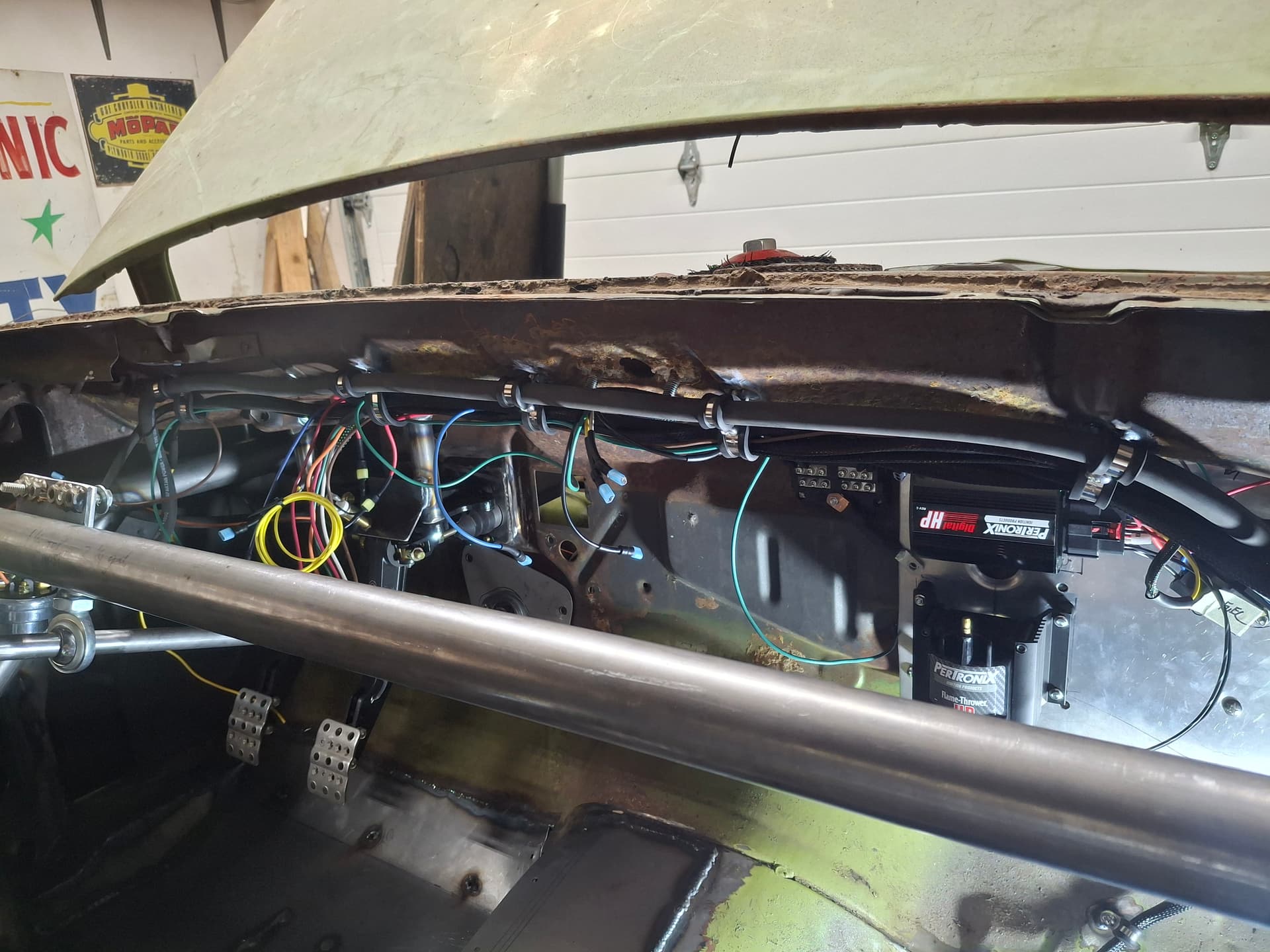
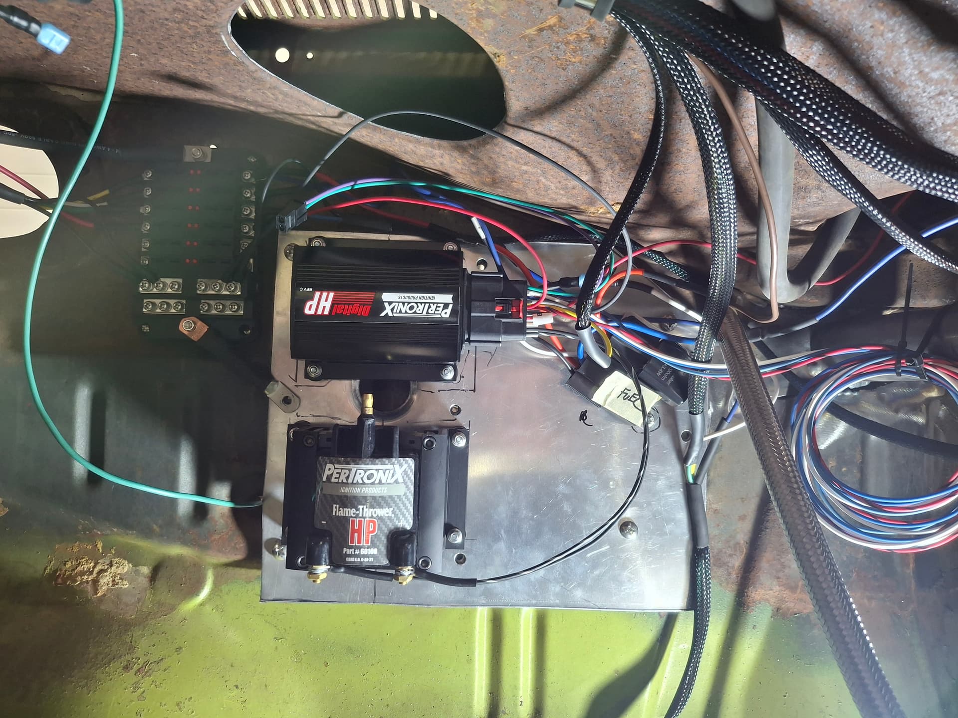
Ignition System
The MSD distributor is about the best small-block Chrysler distributor available as far as ease of curve tuning and accuracy go, so I went with one of them.
The Pertronix Digital HD box is still made in the USA and has some perks over the MSD 6AL including timing adjustment, so I purchased both the Pertronix box and matching Flame-Thrower HP coil. While the instructions for both the ignition box and coil do not mention rubber isolators and none are included, I purchased some and mounted the units to the aluminum panel under the dash after drilling and dimpling some large holes in the panel to stiffen it since the coil is pretty heavy. I mounted the coil low to keep center of gravity down and the lighter ignition box above it.
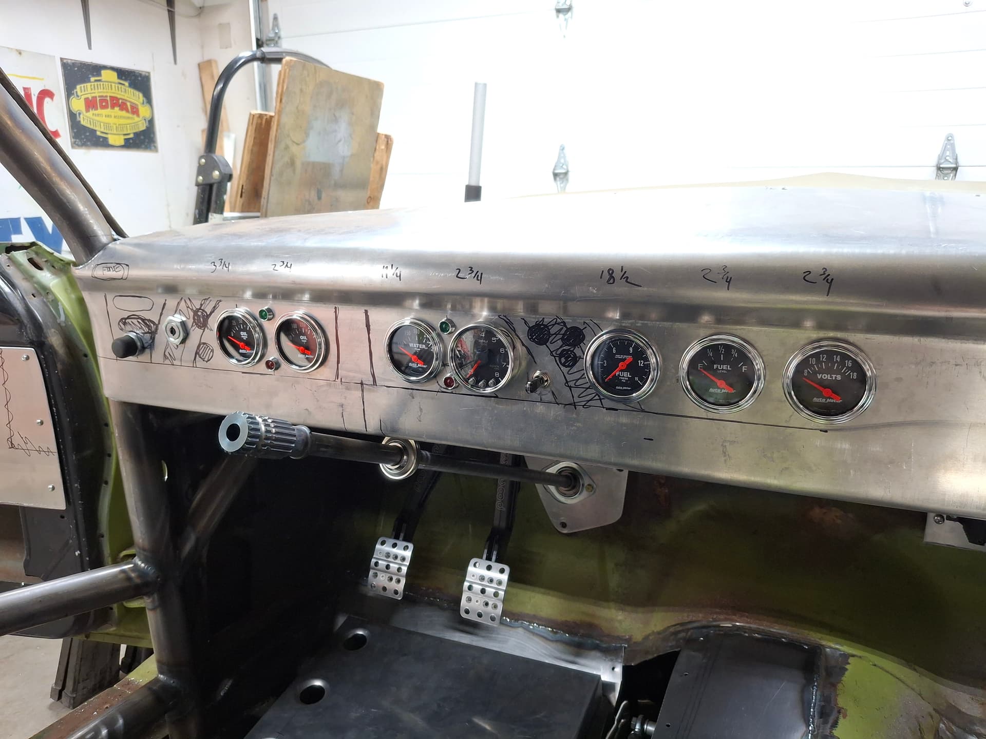
Dashboard
I used two fused circuits for the gauges, one for the lights in the event I decide I need to install a dimmer and one for gauge power. These circuits pigtail at the gauges with a connection for ease of removing the entire dash with all the gauges and indicator lights installed.
The four small LED lights you see are the indicators. The red one between the coolant temperature gauge and tach is the coolant warning light and the green one above it the right turn signal. The red light between the oil pressure and oil temperature gauges is the oil pressure warning light and the green one above it the left turn signal. The toggle switch to the right of the tach is for the turn signals. The black marker arches and column drawn on the dash are the full (as in both eyes) and partial (as in one eye) blind spots when I am seated with the steering wheel installed, so I stayed away from them as best I could.
GPS Data Logger
I haven’t purchased a data logger yet, but I ran the power and ground for it to where it will mount below the fuel level/volt gauges. I’m considering a Garmin Catalyst thanks to Jon @jonUU demonstrating his for me at his house, but I’m open to other suggestions since it will be one of the last purchases if the budget even allows.
Post Alert Pings:
@Sportsracer
@Datsun78
@Bob_Alder
Thoughtful planning and skillful execution Justin. Speaking from personal experience, I might suggest modifying your oil pressure warning light (size, brightness, and location), something that’ll quickly get your attention even as your eyes are focused on the track far ahead.
I installed a pair of LED trailer running lights right at the top of the IP. These oil pressure and fan (air-cooled) warning lights are large (~1-7/8") and bright! Keep up the amazing work!
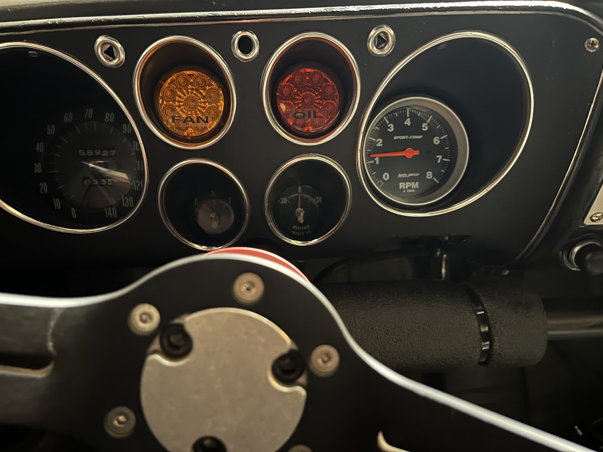
Those are some honking alarm lights, Jon @jonUU! They’ll get your attention for sure. I wish I had more room on the dash directly in front of me. You bring up a good point. I sat in the car and focused on the driving line, and it might be worth swapping the LED lights to where the red alarm lights are at the top closer to my line of sight and the green turn-signal lights at the bottom. I think either position would catch my attention, but the quicker the better.
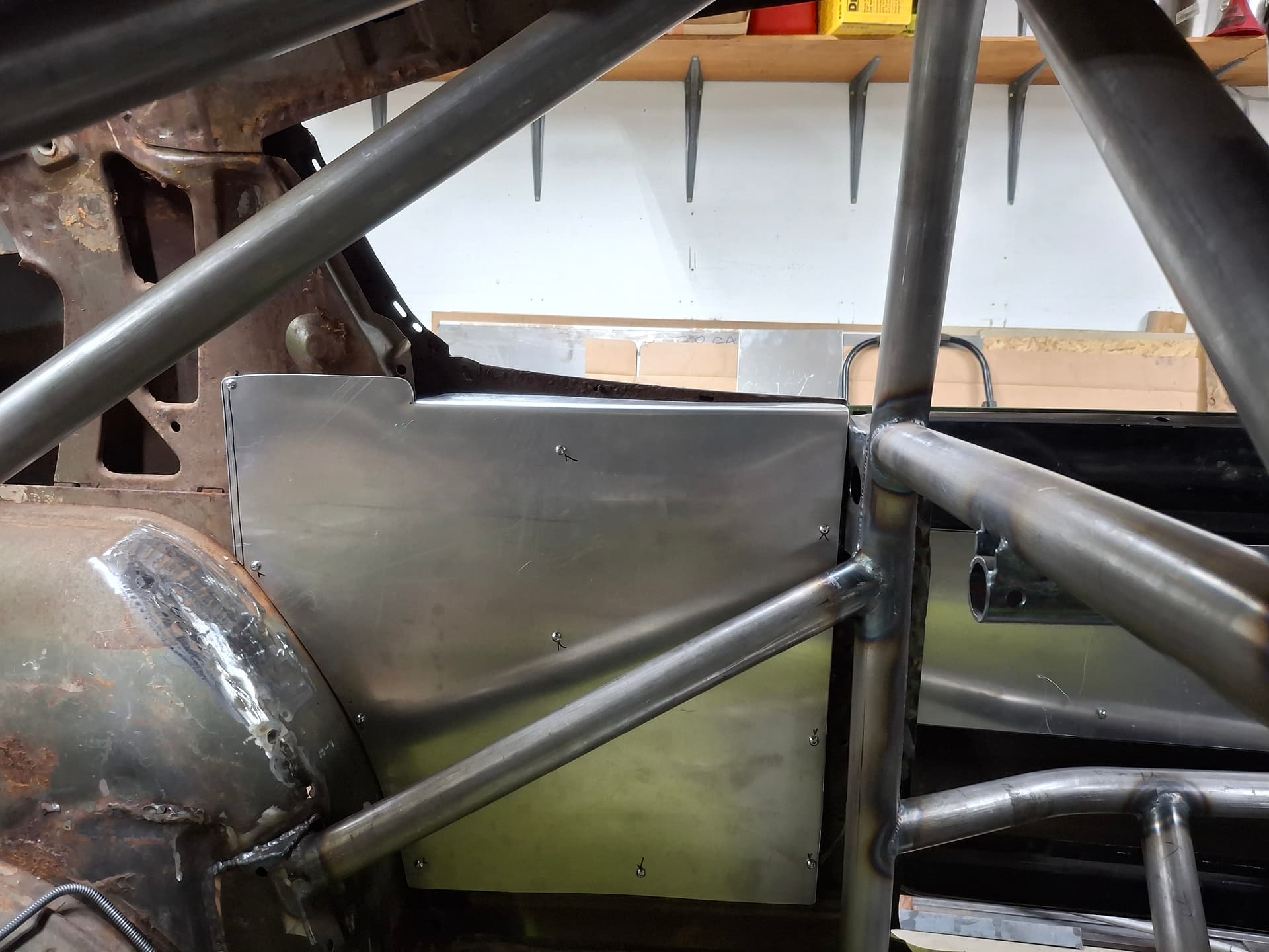
Door Panels
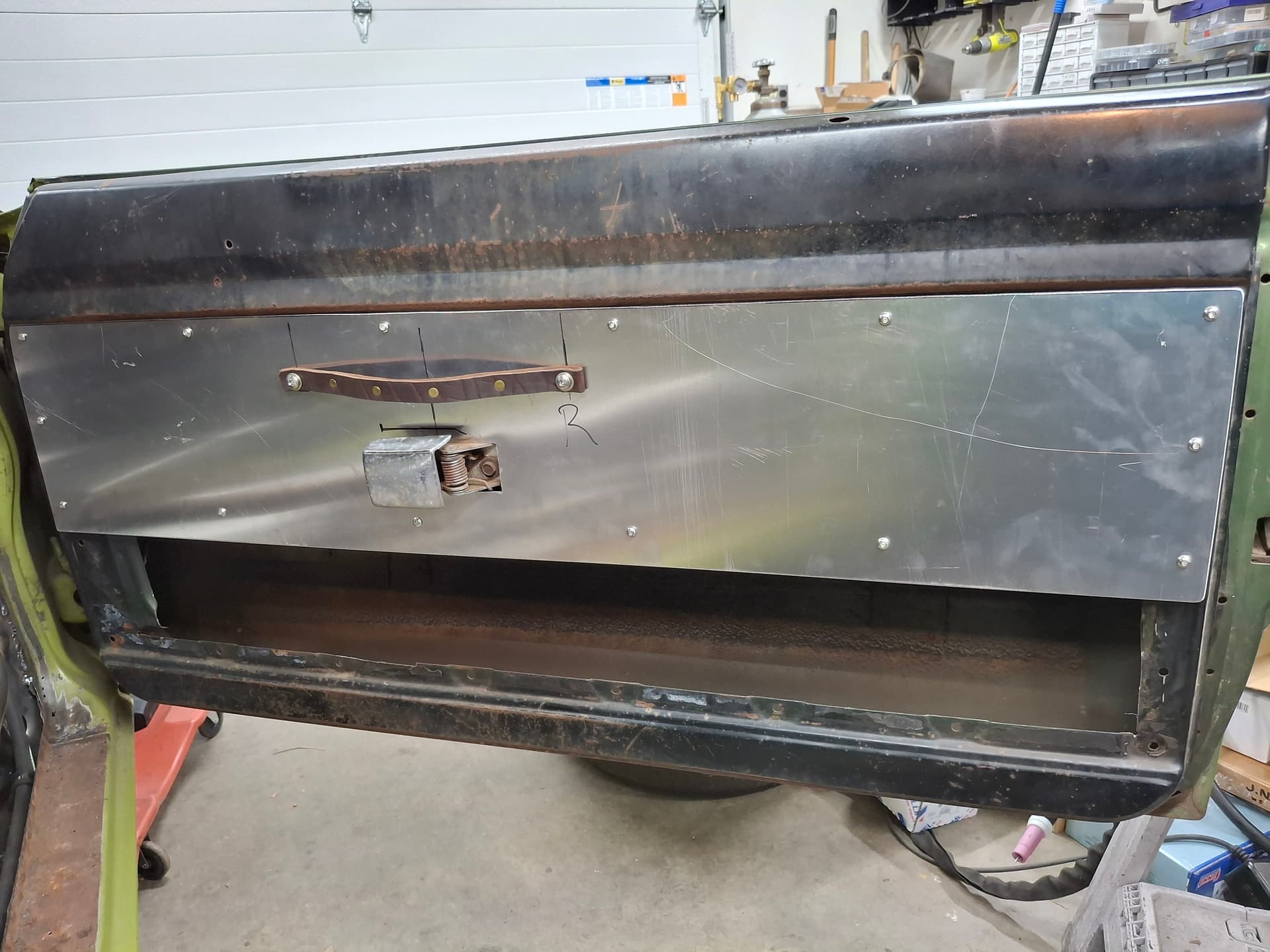
I decided to tackle the door panels. I used 0.064" 5052 aluminum sheet that will eventually get painted. For the quarter-window panels, I drilled and tapped #10 holes into the inner body panels. For the doors, I drilled holes and through-bolted with #10 screws.
I maintained the factory inner door latch lever but needed to deal with no longer having an armrest for pulling the door shut. The way the driver’s seat is positioned, I can’t reach the outside door handle to pull the door shut, but I don’t want an inside pull handle obstructing my elbow movement. I decided to give a leather handle a try but couldn’t find reasonably priced, thick leather strap. I ended up purchasing an inexpensive $12 leather dog leash, folder it over and riveted it onto itself, and through-bolted it into a reinforced section of the door panel with 1/4" screws. It was my first time working with leather, so add that to my toolbelt. We’ll see how well it holds up.
Post Alert Pings:
@jonUU
@Sportsracer
@Datsun78
@Bob_Alder
I had a busy weekend. Aside from hanging out with @Nick_H Friday evening, I finished plumbing the brake and clutch systems, fabricating the throttle pedal and linkage, and finished the foot rest.
Brake and Clutch System
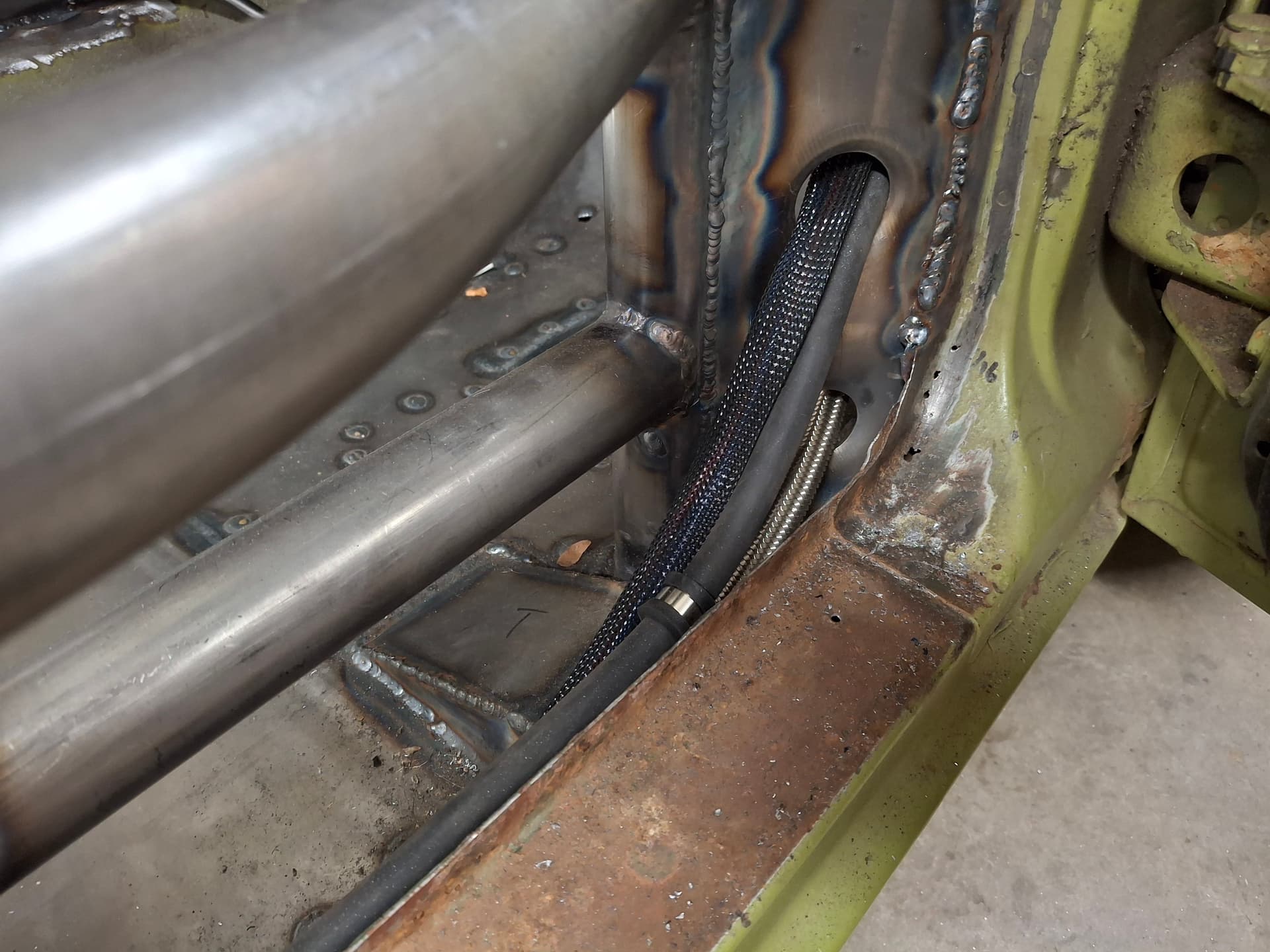
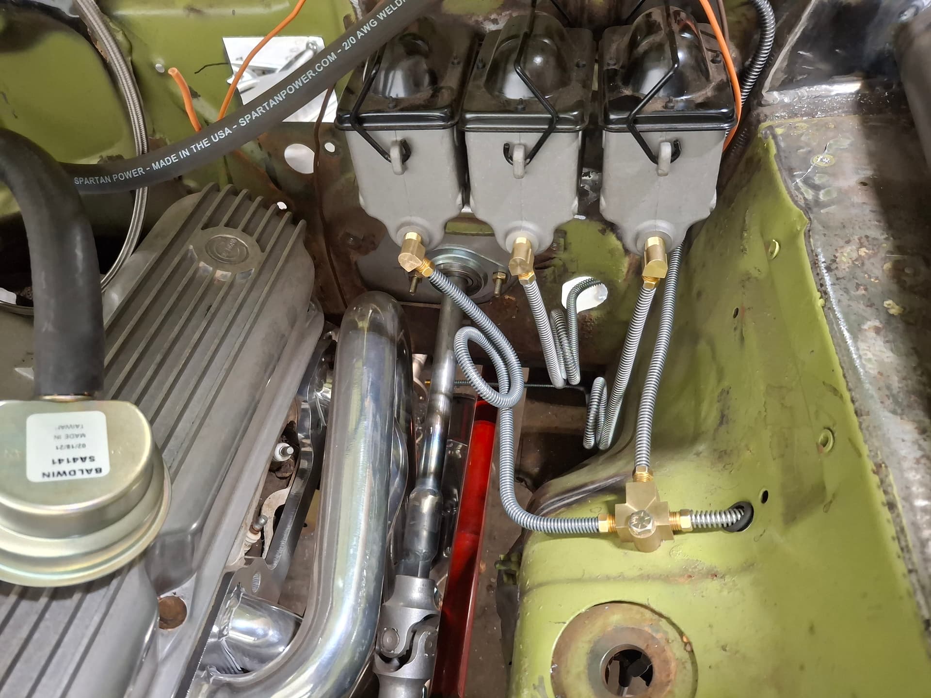
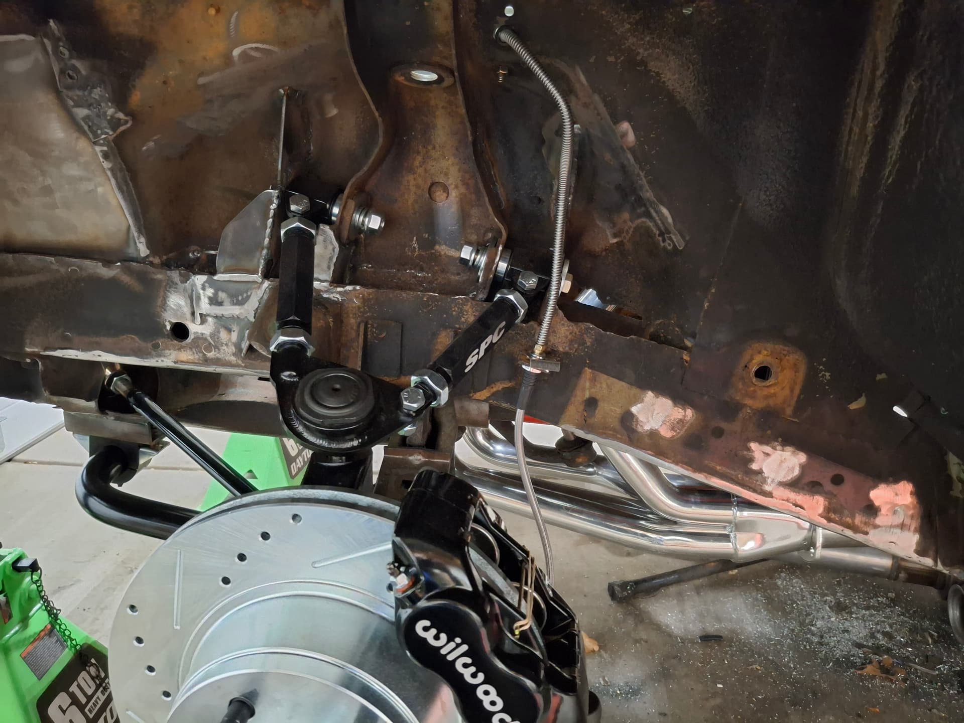
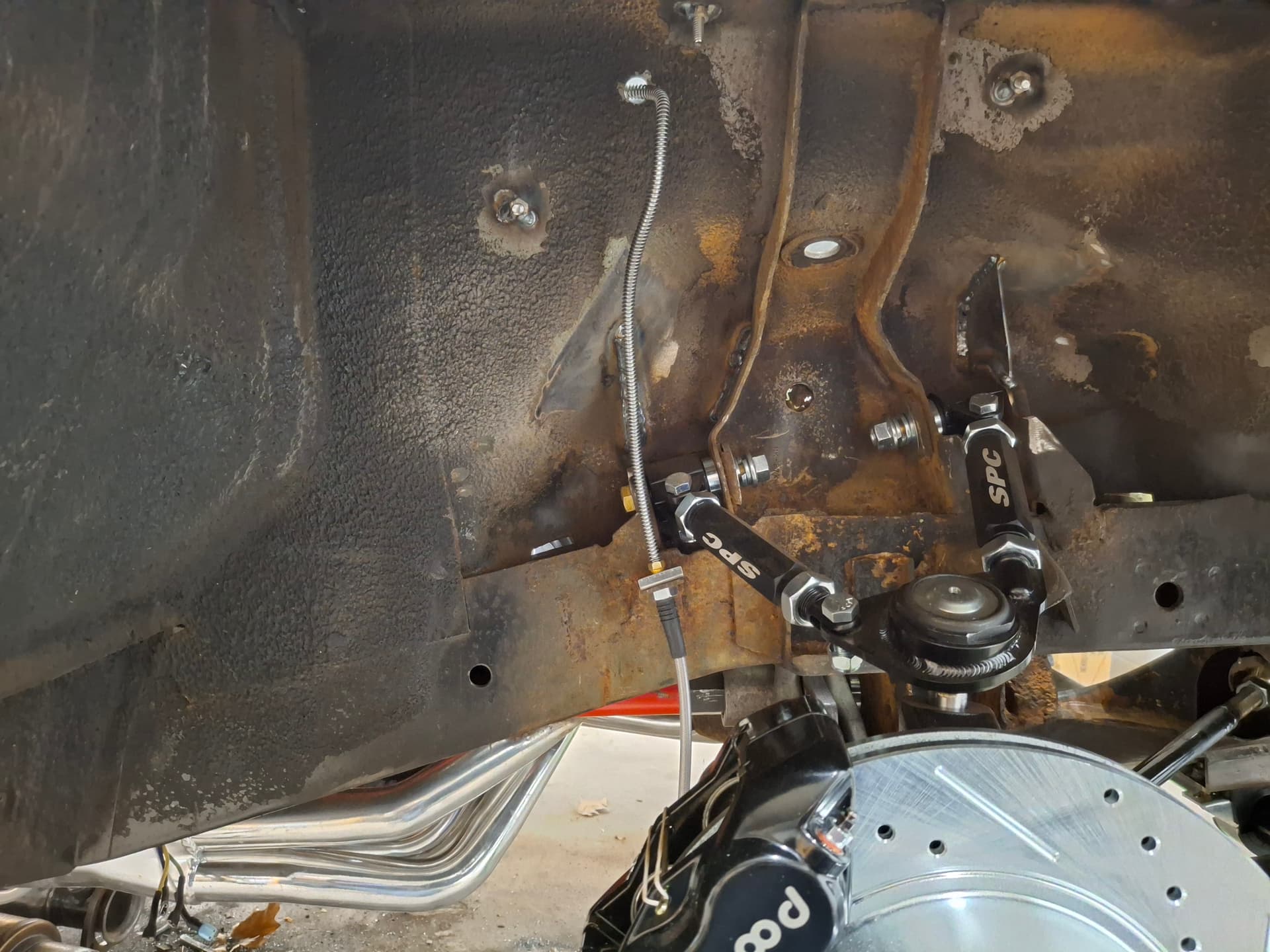
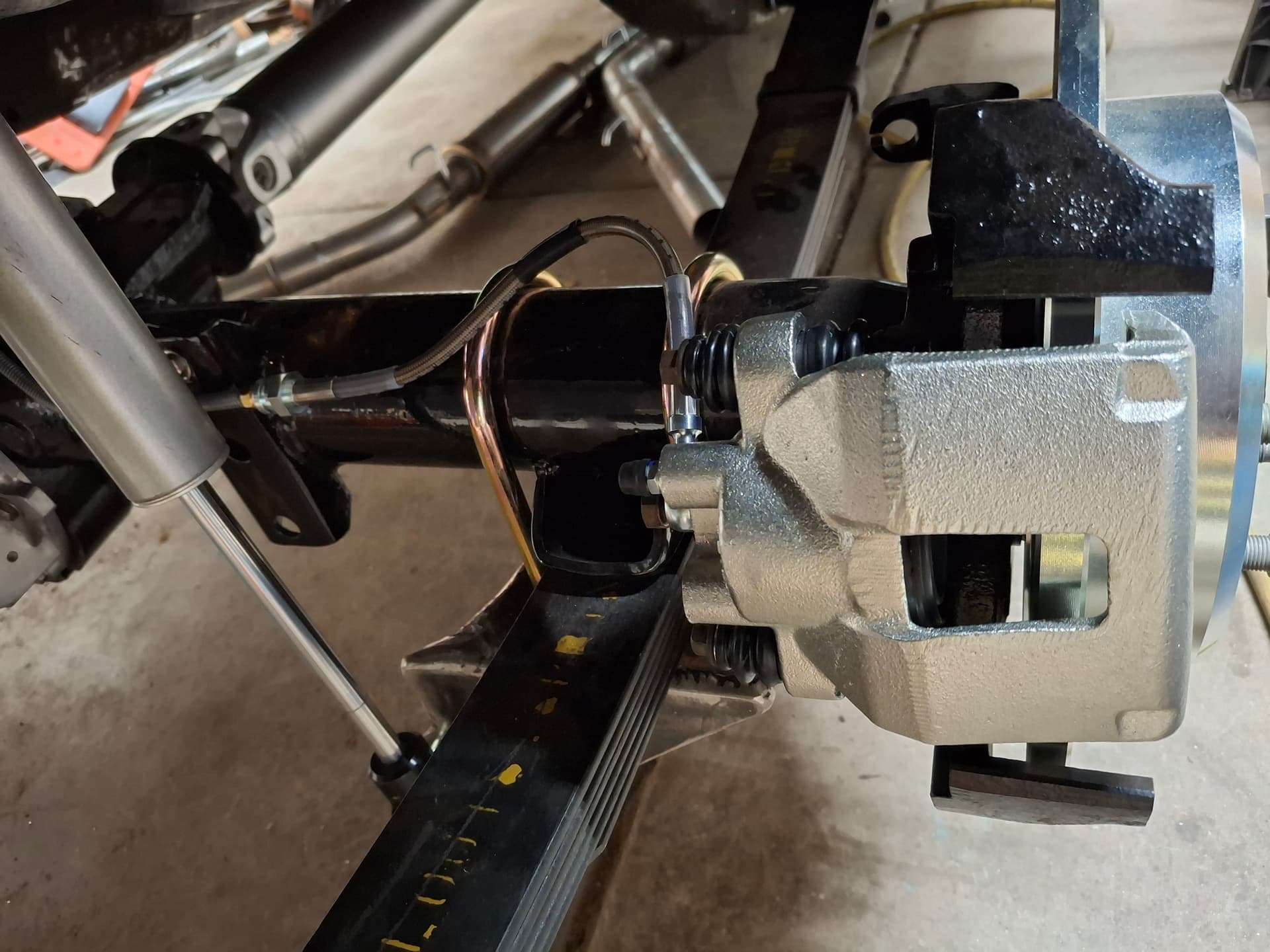
I ran 3/16" hard lines with double-inverted flare ends and -3 AN braided stainless at the flex connections. The front line runs from the master cylinder to a tee. The left line runs down to the caliper hose, and I routed the right brake line up along the top of the firewall to keep it away from heat as much as possible. I still need to secure this line with Adel clamps.
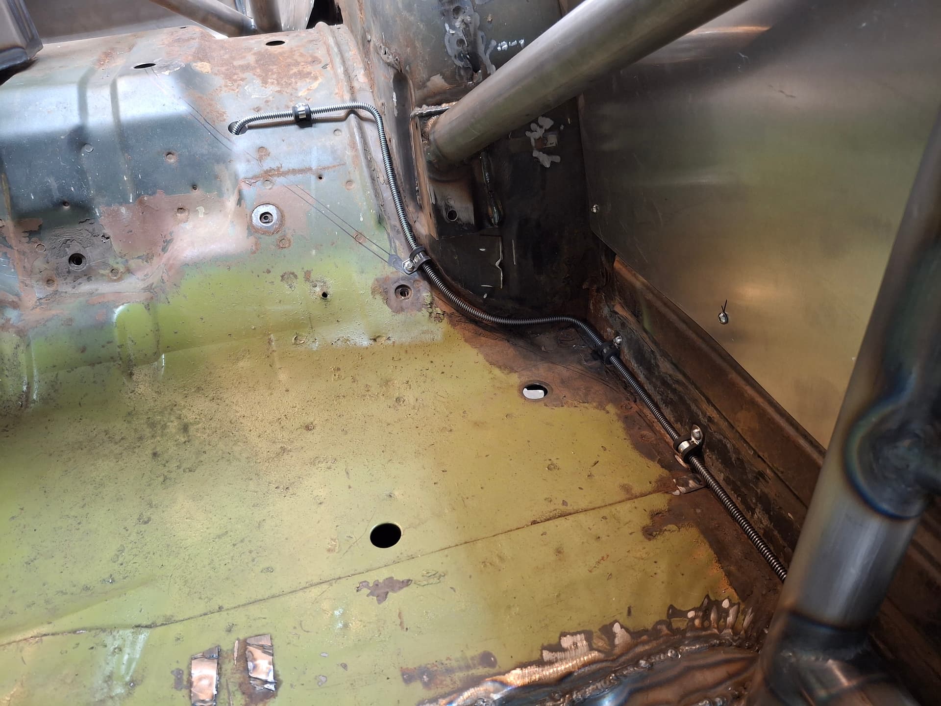
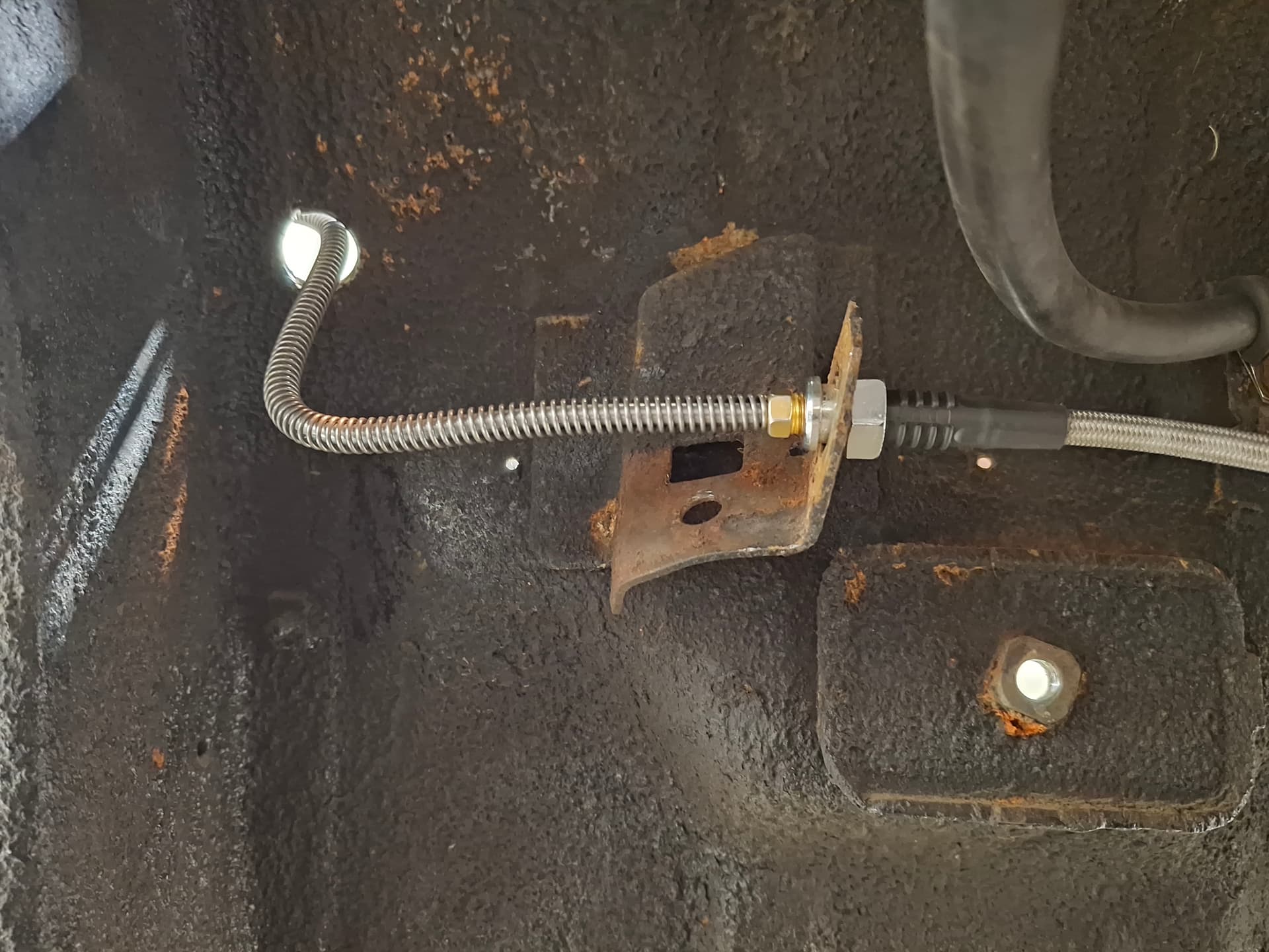
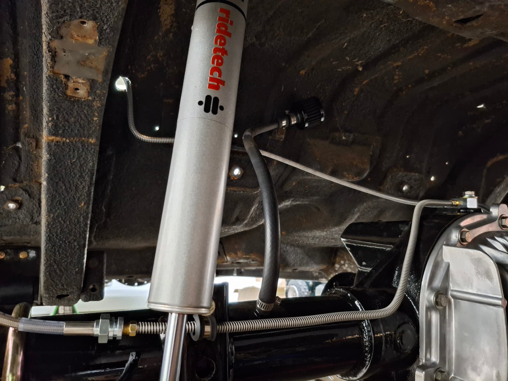
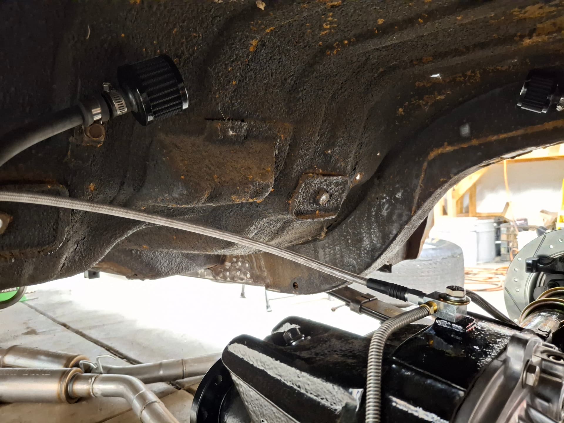
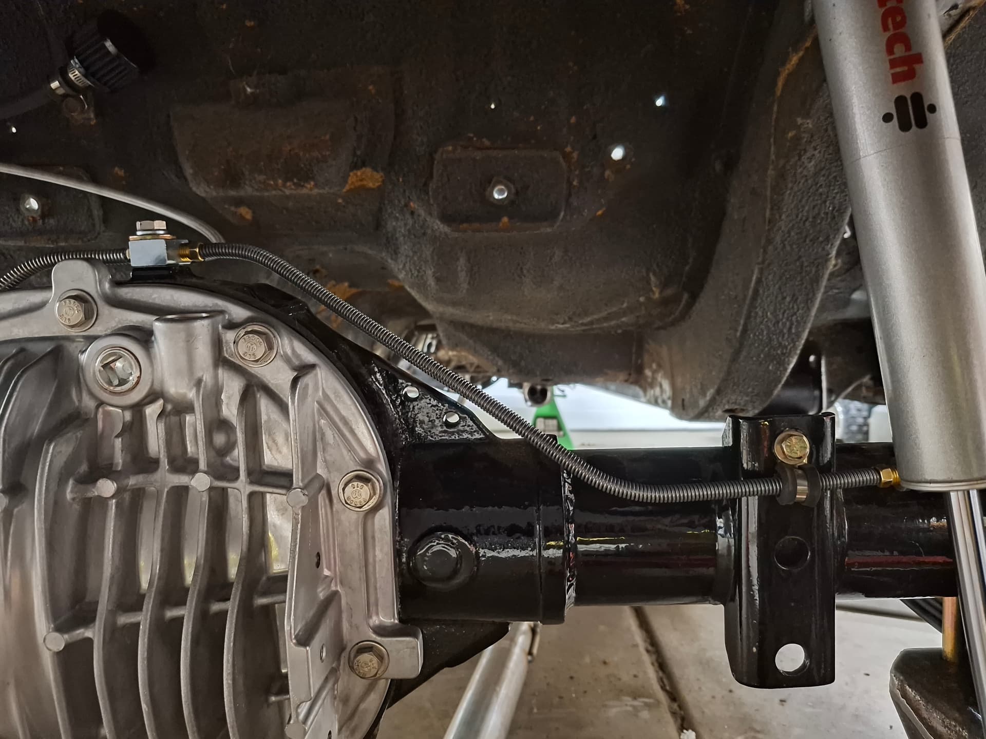
I couldn’t run the rear line underneath the car because the protected route inside the frame rail would run it parallel to and within 3" of the exhaust, and running it outboard the frame rail along the rocker panel away from exhaust heat would require bends down and around two crossmembers, exposing it to possible damage from jacks and road debris. To keep the line cool and protected, I ran it inside along the left rocker panel and then through the floor to the rear end.
The clutch line runs from the master cylinder down to the frame rails where it converts to the throw-out bearing -3 AN braided stainless hose.
How about those late 1960’s Cal Custom aluminum valve covers I scored? ![]()
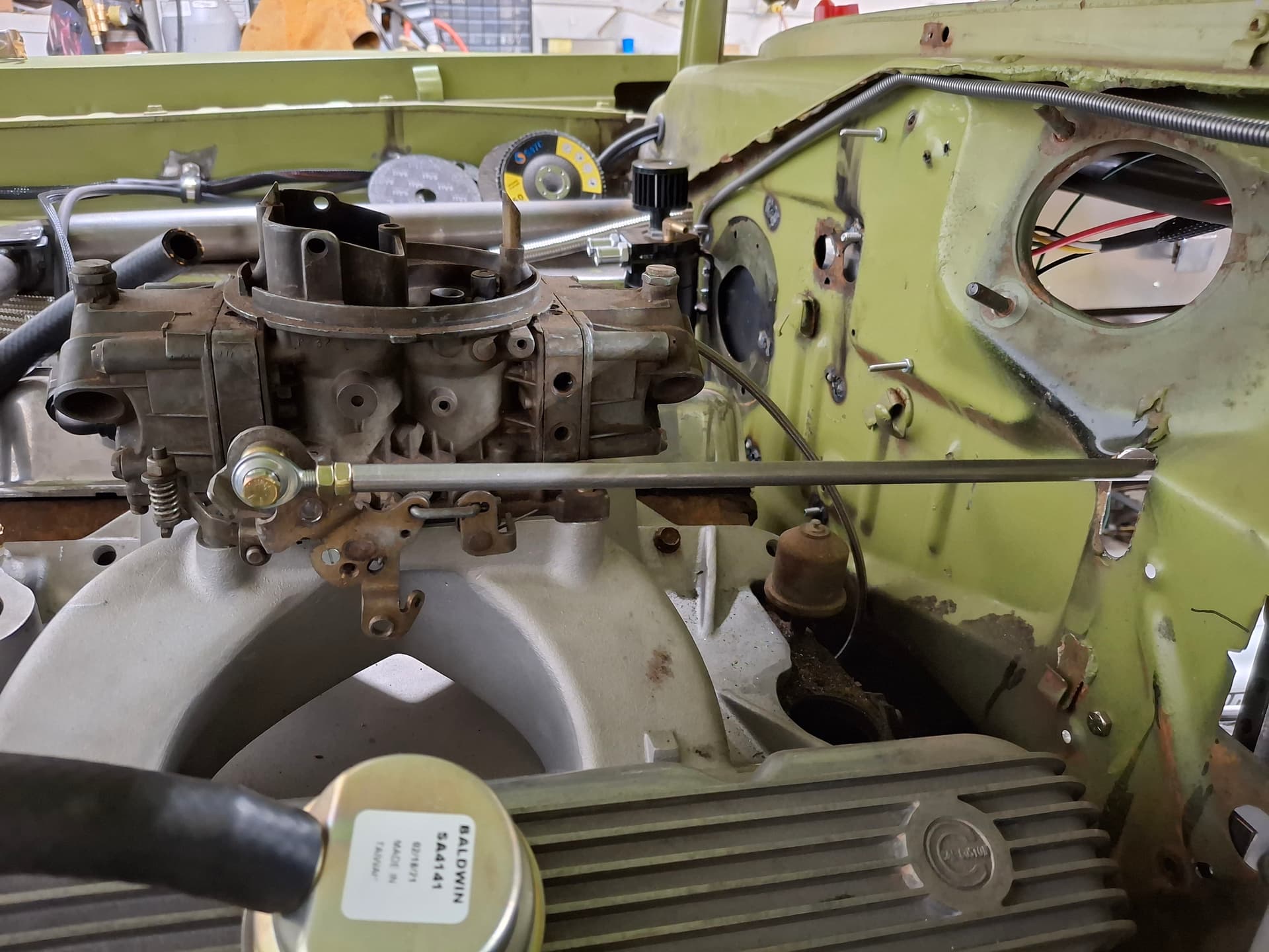
Throttle Pedal and Linkage
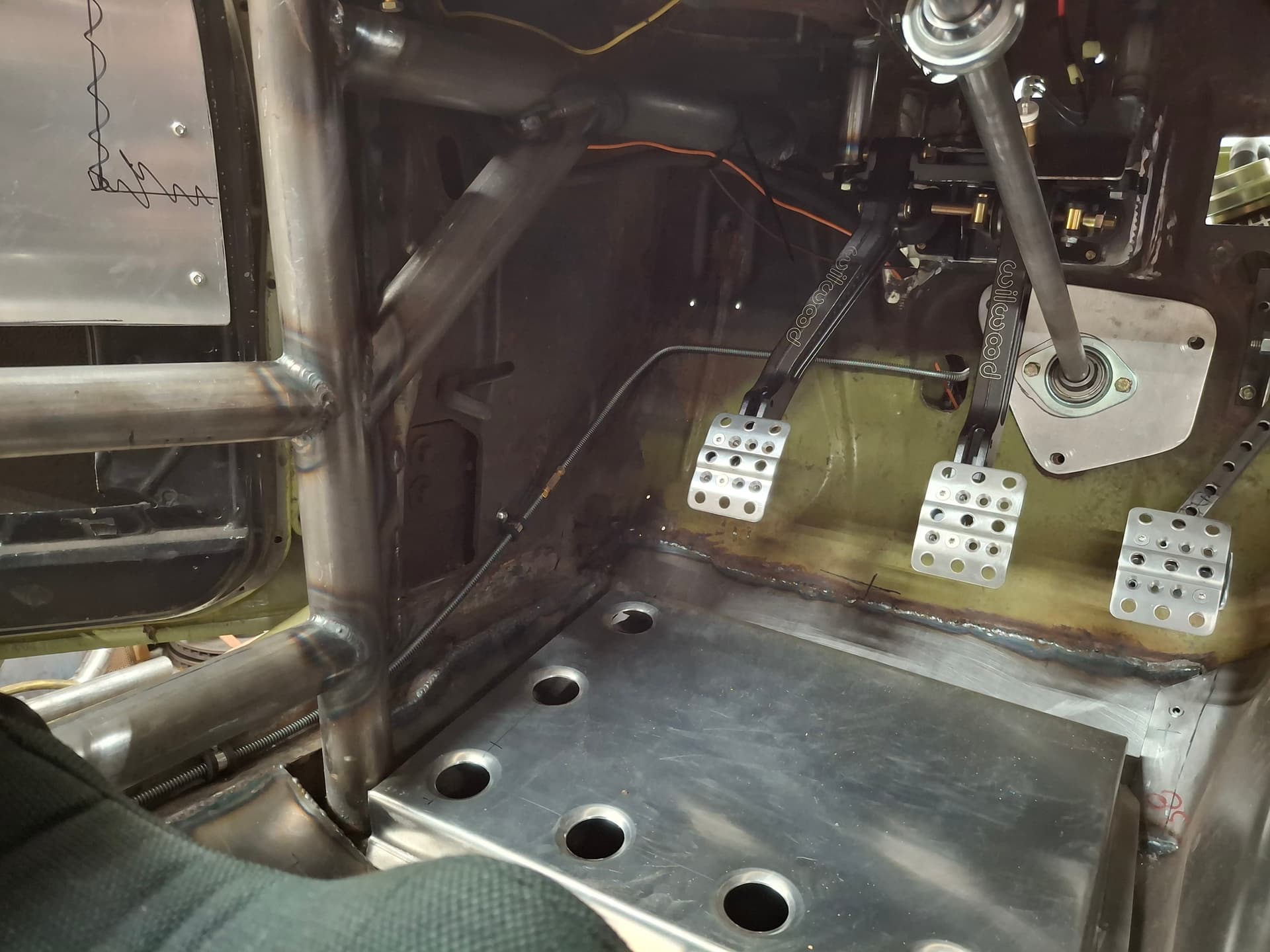
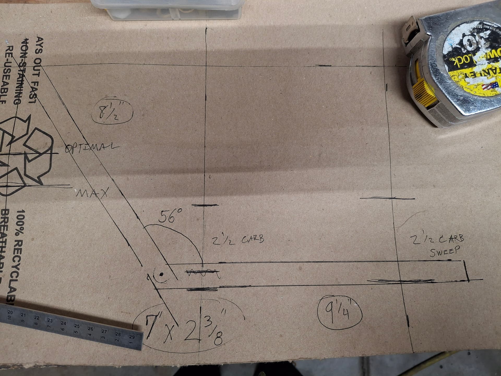
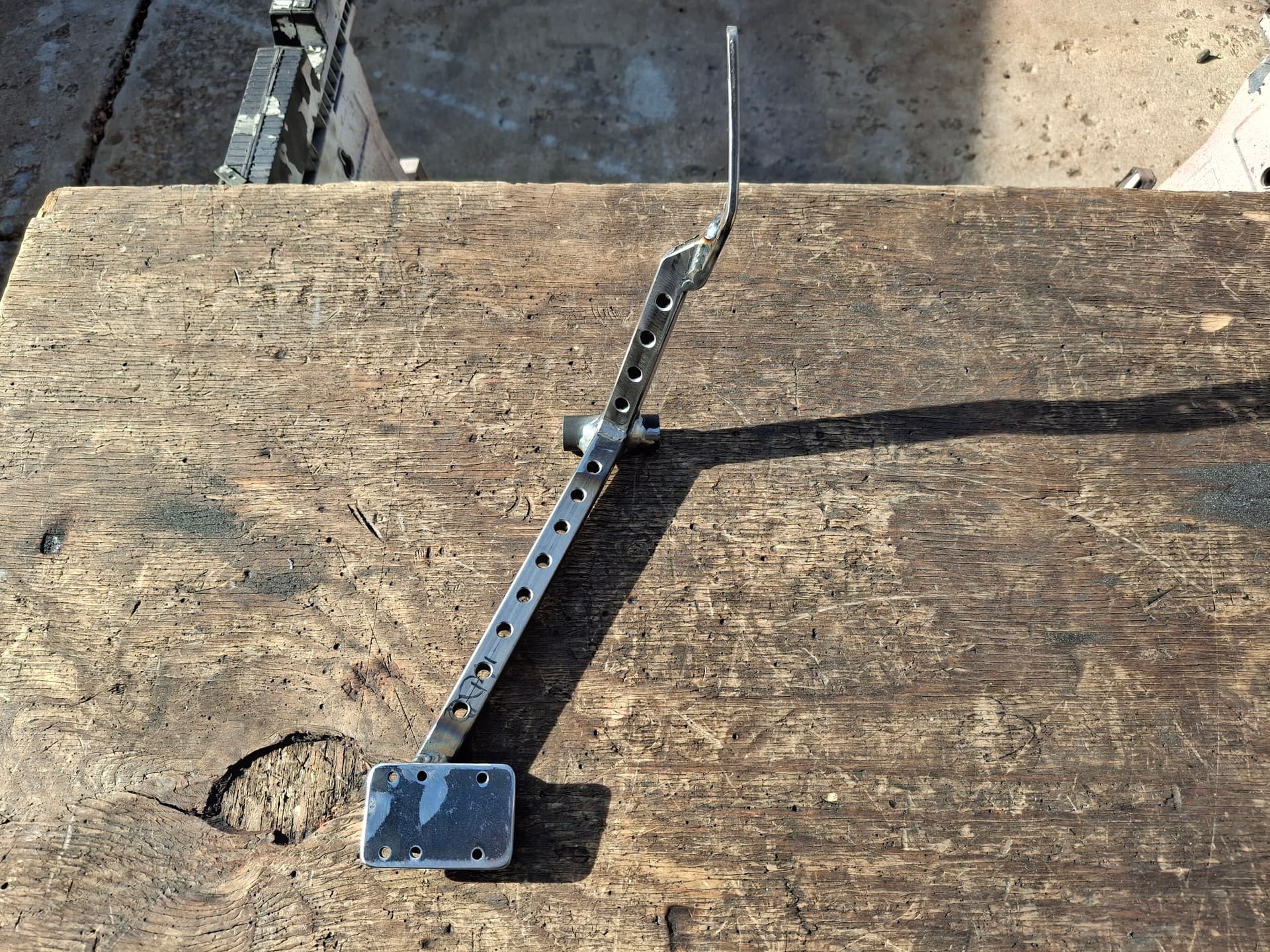
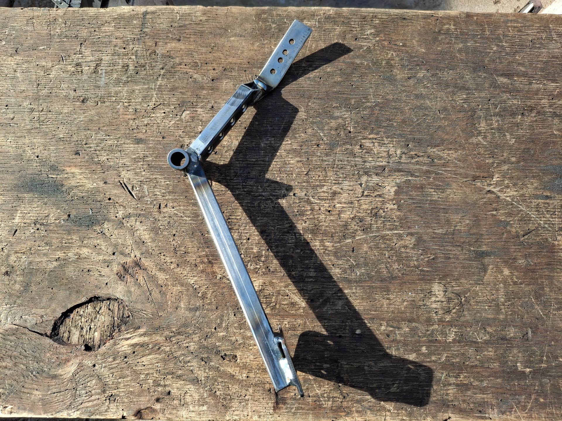
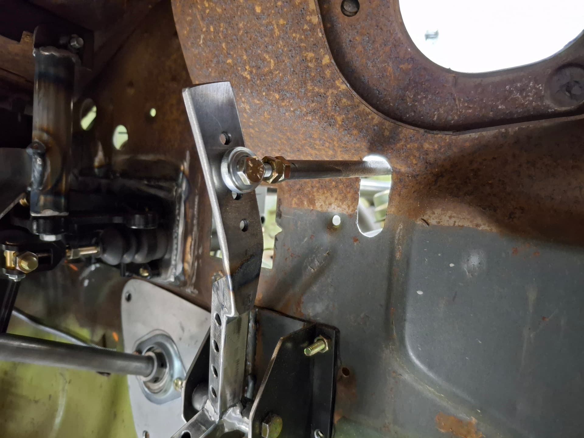
I wanted a stout throttle pedal assembly that I don’t need to worry about flexing or bending, especially since the brake pedal and foot configuration is going to require I do a type of side-foot heel-toe downshifting where I will load the side of the throttle pedal. I built the pedal from 1/2" x 0.625" square tubing drilled to lighten it and a firewall mount from 0.120" steel sheet. I used a 3/4" spud at the pivot with sintered bronze flanged bushings and a 3/8" bolt.
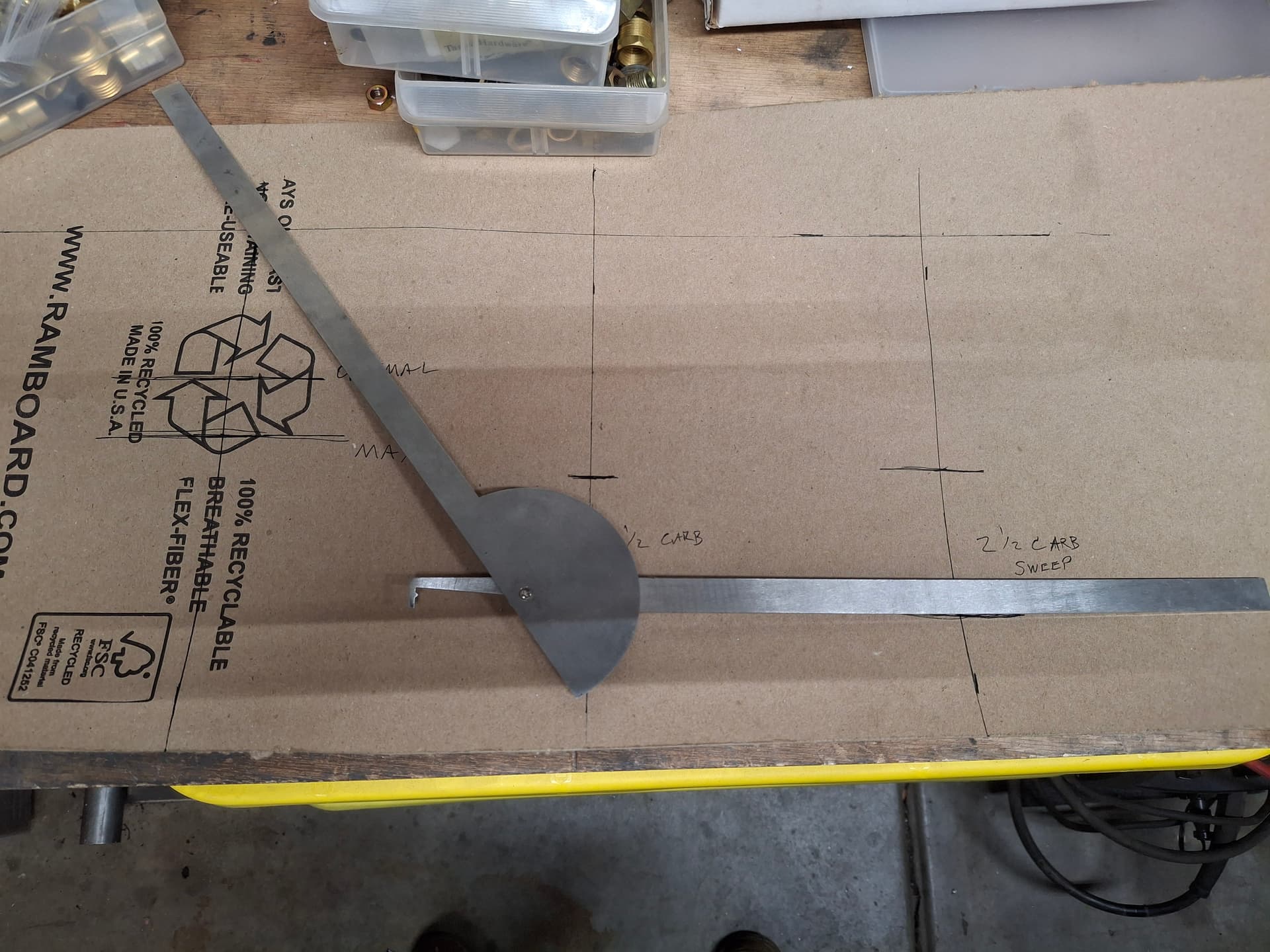
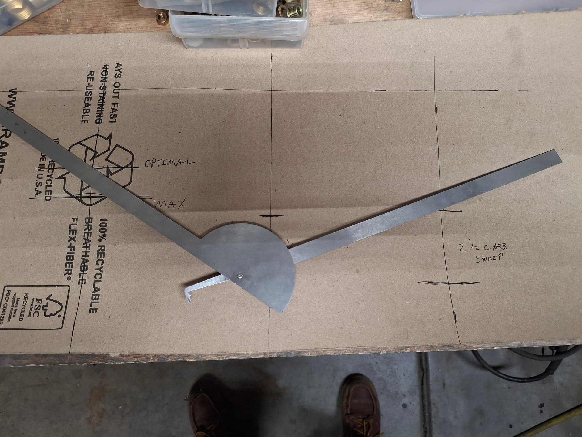
After taking general measurements, I started on card stock drawing out a pattern and playing with the ratio until I was able to achieve 2-1/2" travel at the carburetor and 2-7/8" travel at the pedal. When fabricating, I gave myself extra adjustment holes at the linkage lever and ran it wild in the event I need to shorten or lengthen the pedal travel; I’ll cut off any access lever once I test and tune. At the pedal, I drilled and tapped a plate to accept a Wilwood pad that matches the brake and clutch pad. For linkage, cut an oval slot in the firewall and ran straight 3/8" steel tubing with 1/4" rod ends threaded in. I need to weld a nut onto each end for additional thread strength, which isn’t pictured. Overall, the pedal action feels great, so hopefully it functions well with the engine/gearing behavior.
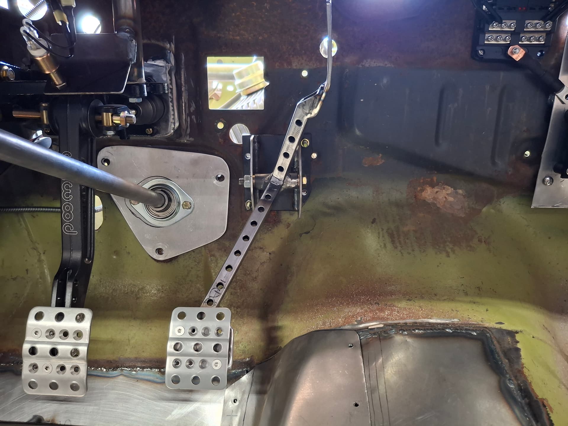
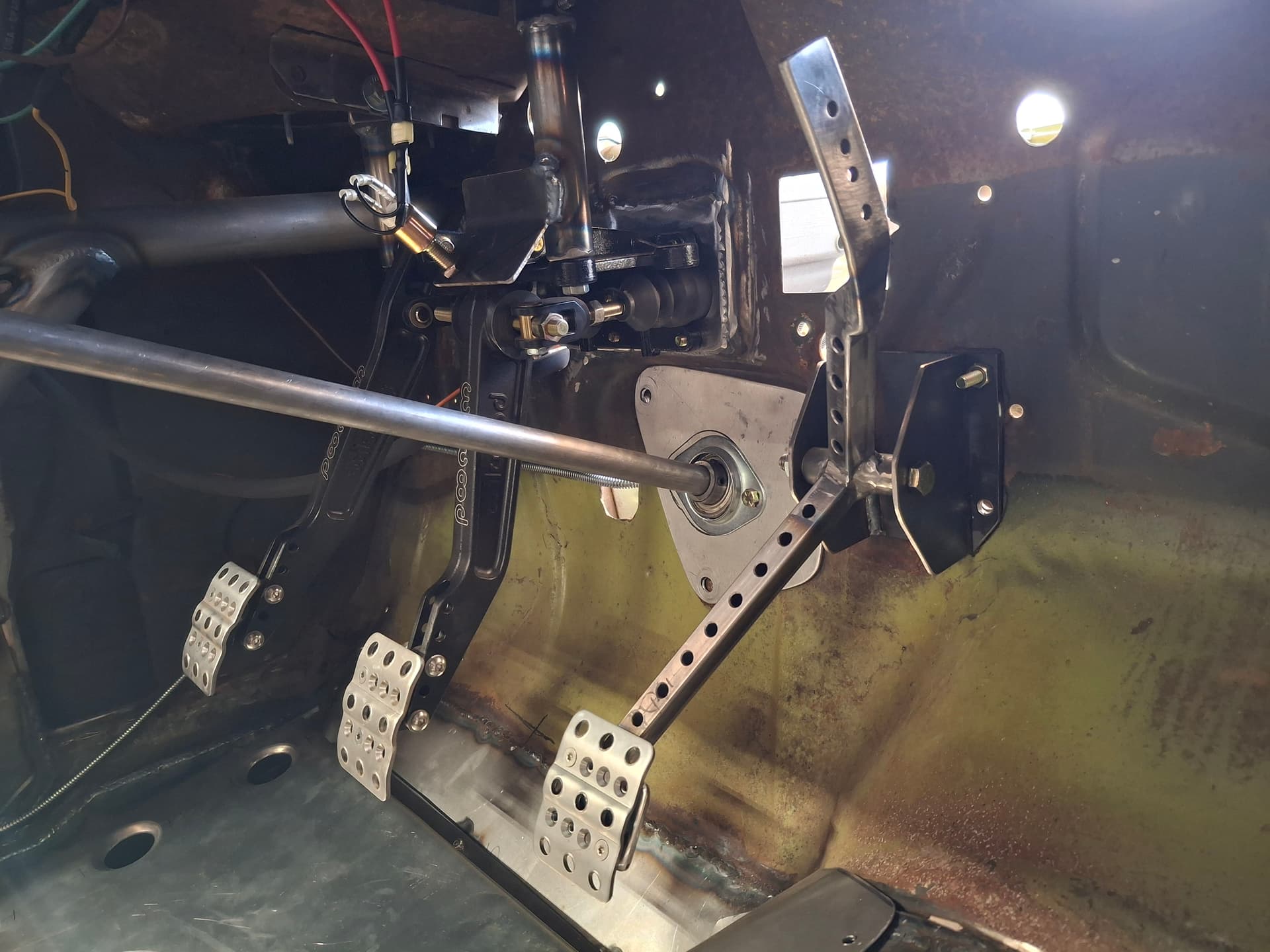
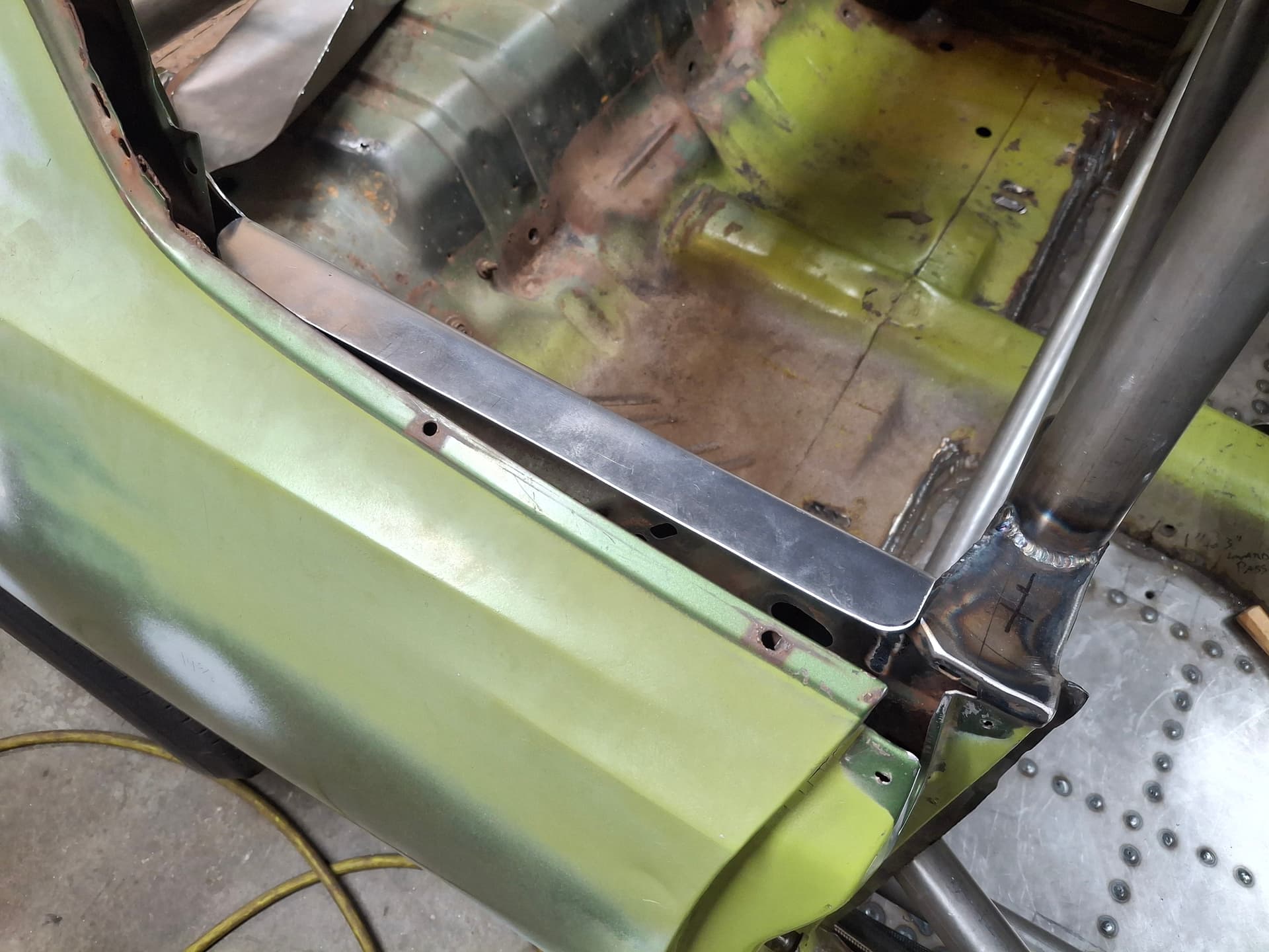
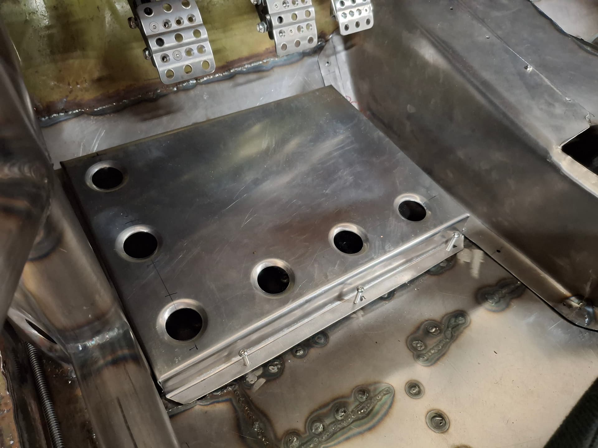
Foot Rest
Due to the headers, I couldn’t lower the swing pedal assembly any further, and my feet rested where the pedal was too far toward my toes than I prefer. On the work bench, I broke up a piece of aluminum sheet as a foot rest and drilled and dimpled holes to stiffen it. I drilled holes through the floor and welded in #10 nuts that accept the #10 screws to secure the foot rest. If I find during testing and tuning that I could use heel blocks, they will be easy to bolt to this raised panel.
Post Alert Pings:
@jonUU
@Sportsracer
@Datsun78
@Bob_Alder
@Rich
@Nick_H
Justin
Thanks for posting update and pics. The detail work on the pedal assembly looks great! I’m looking forward seeing your car at the track.
Will it be ready for the 26 racing season? Are you going to do a few test days at HPR prior to the first race? If you are, and don’t mind my being there, post up when and I’ll try to make it. With race days being kind hectic I’d hate to bug you by looking at your car then.
Tom
Hey Tom,
Yes, my goal is to be on track by RAKC in September 2026. The biggest unknown variable is when I’ll have the engine block back from Pete Christensen who is doing the machine work so I can start building it, and then when I will be able to get back up to Pete’s to break in and tune the engine on the dyno. I have all the parts ready to go, so building the engine won’t take long. If all of that can happen sooner, I may be able to make an earlier race, but I’m shooting for RAKC. For now, I’m scheduled to complete driver’s school this spring to get my provisional comp license. Tom Penewell is kind enough to let me use his Spec Miata, and Bob Hill is kind enough to serve as my instructor.
Once the Barracuda is track worthy, my plan is to take it down to La Junta for a weekend for shake down and test/tune. While I’d prefer HPR since it’s closer in case I need parts, I’m told I’ll get a ton more time on the track at La Junta than I would at HPR. I’m planning on putting out the word when I’ll be going down there to see if a group of RMVR people want to join for test/tune/practice, so I’ll keep you posted. Otherwise, you’re always welcome to drop by my house and have a look.
Justin
I don’t think your contact info is listed on the RMVR members list. I’d rather not post any private info on a “public forum”, and I’m guessing you feel the same. My info is listed;
Tom Quaranto
Reach out via email, maybe sometime after the holidays I can stop by.
1 Like
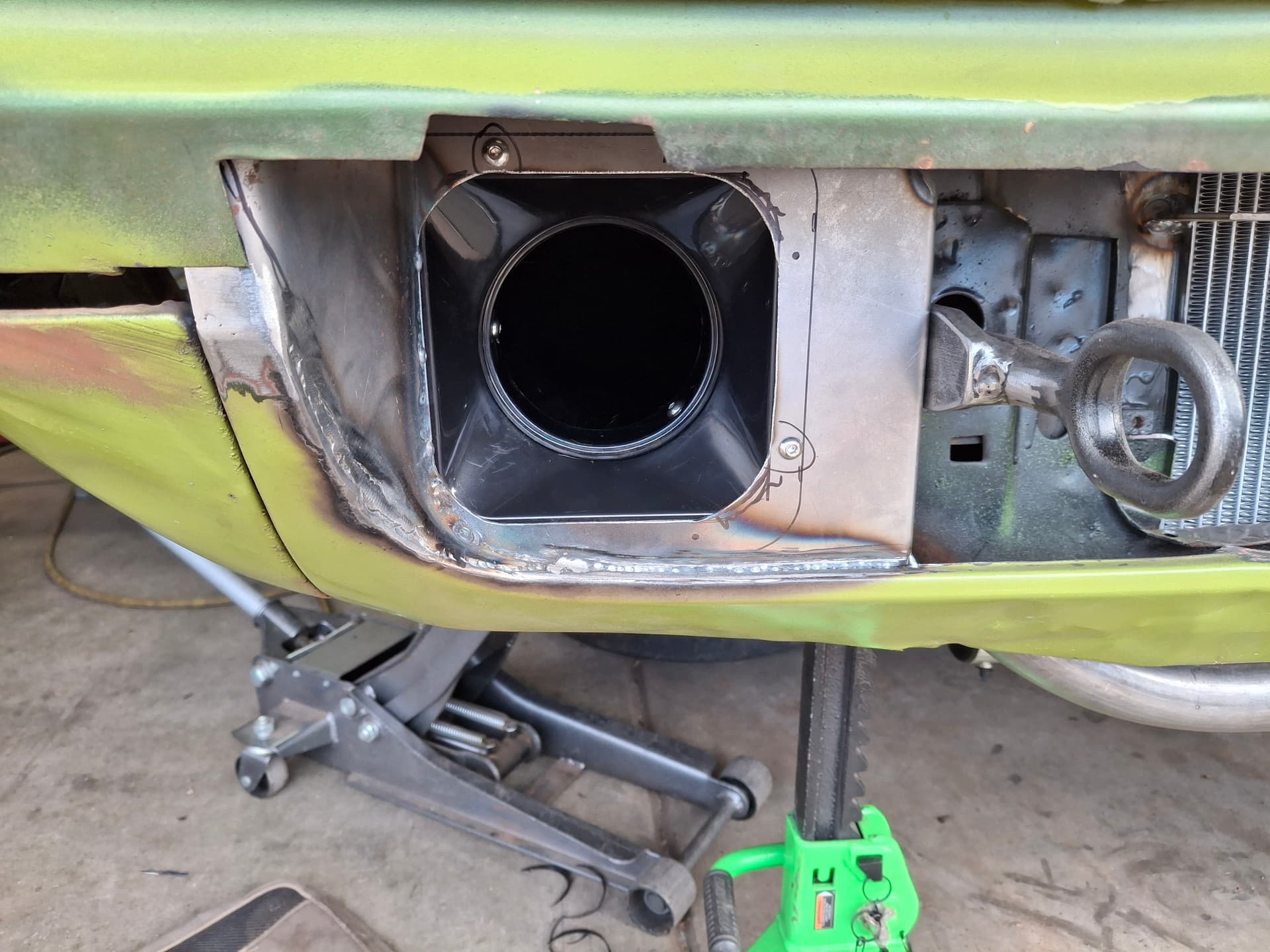
Front Brake Cooling
I finished fabricating the front brake cooling system. Ideally, I wanted to build a shroud that encapsulated the center of the hub and pipe in fresh air to pinpoint the air into the internal rotor and out the cooling vanes. However, the way the A-body spindles are shaped leaves extremely little room between the spindle and rotor braking surface, so such a system is impossible and would likely harm the rotor’s cooling design as an air pump by restricting the flow.
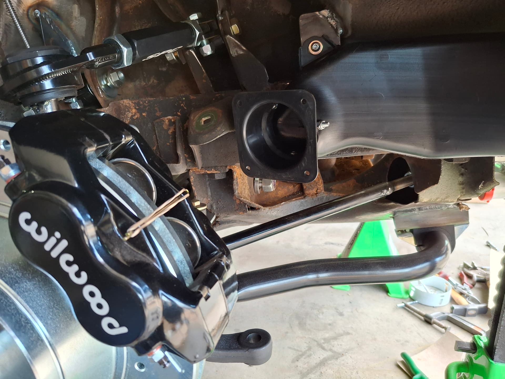
Instead, I chose to keep the air duct farther away and focus it in the directed on caliper to help cool it and the fluid and to provide fresh air to the general area of the rotor center for the rotor vanes to pick up.
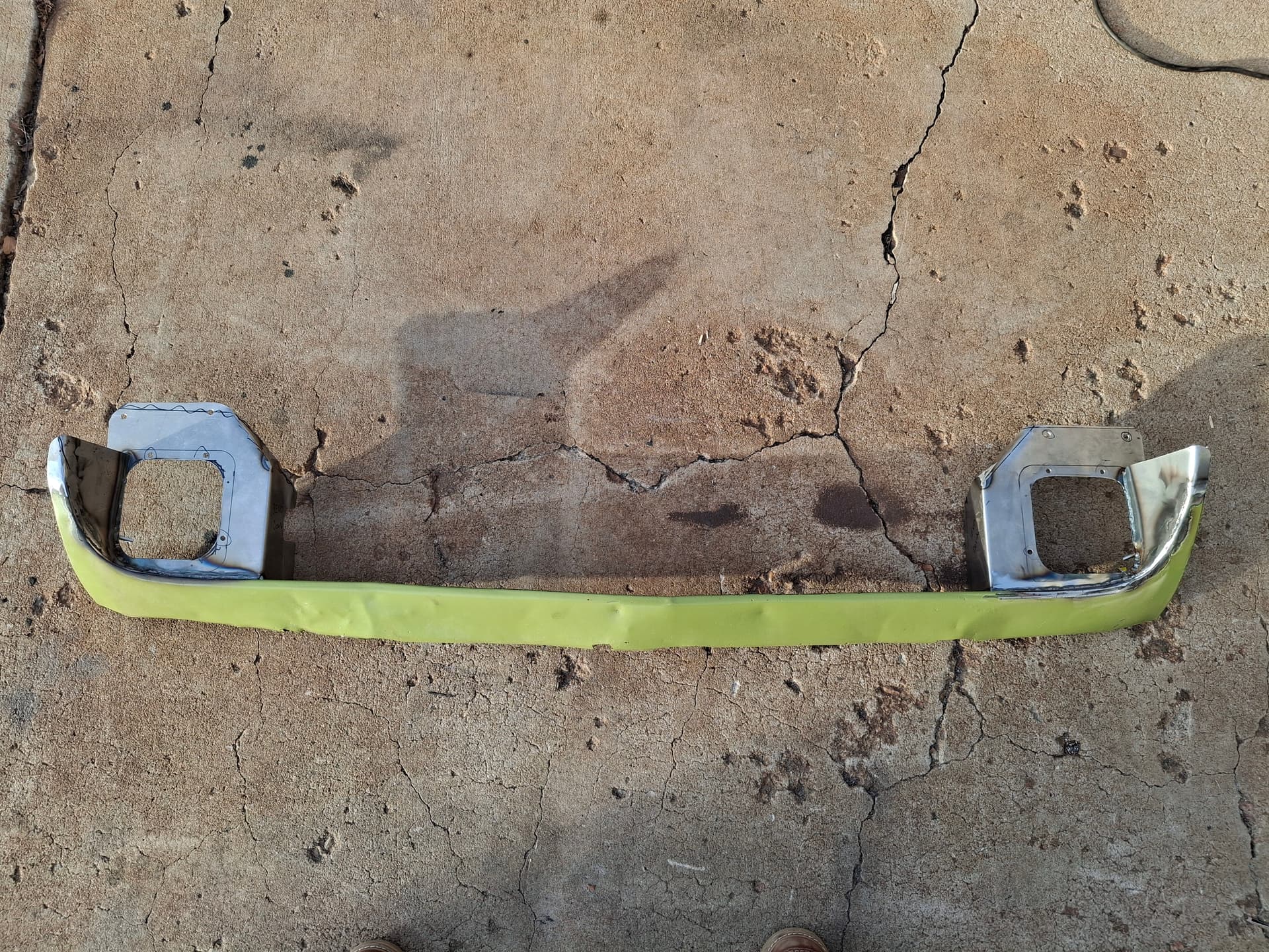
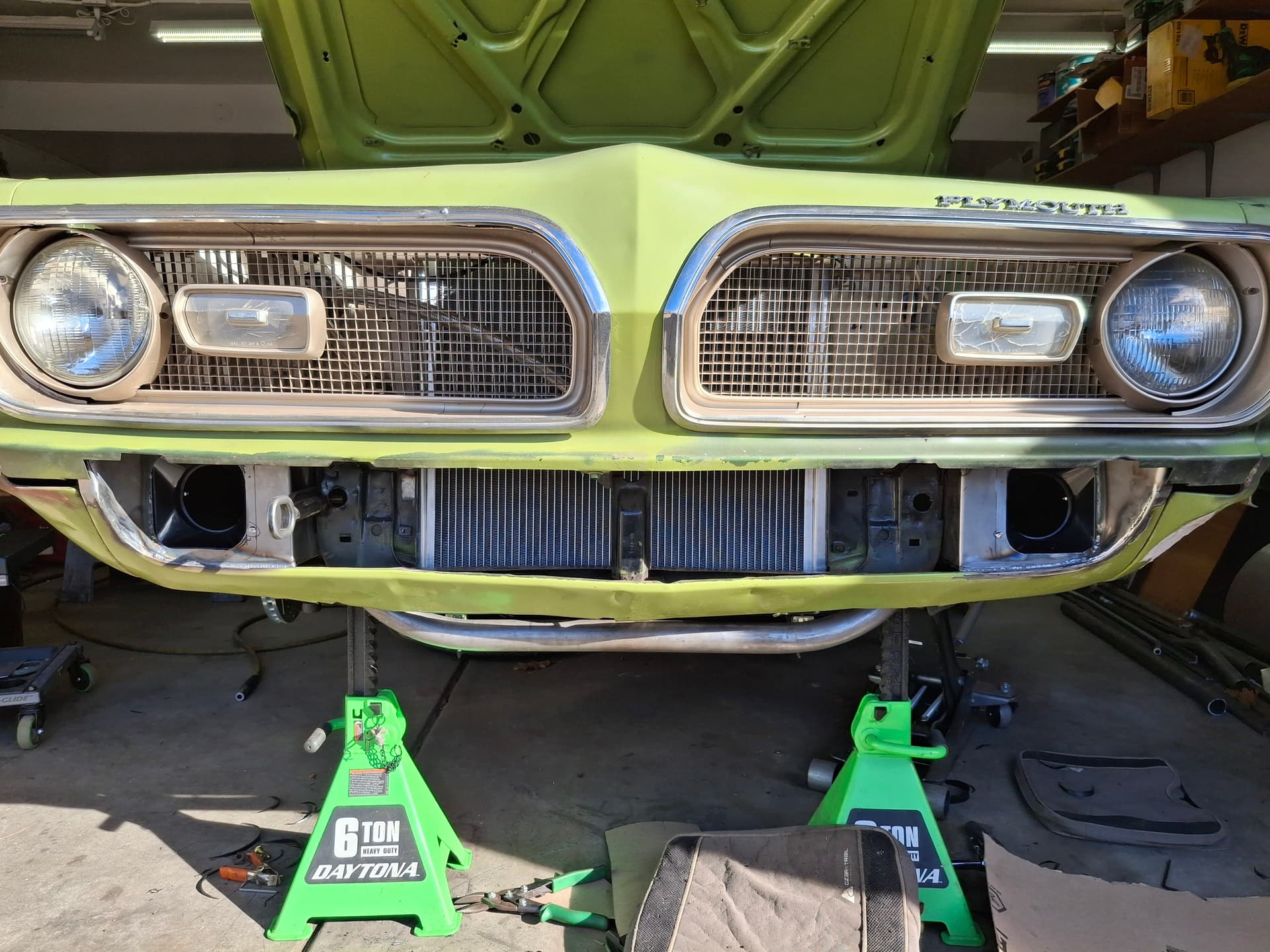
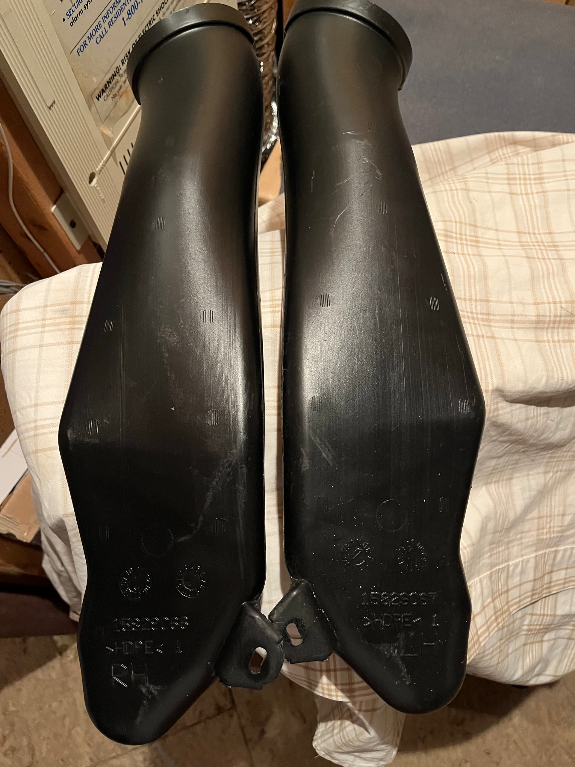
The first component I started with was the actual duct. I was going to use 4" neoprene-cloth flex duct, but my Barracuda racing friend in the Midwest Brian Garcia pointed me toward a duct from a 2005 - 2013 C6 Corvette that pinches down for tire clearance. The right and left ducts mirror each other, but apparently the left/driver side ducts have been backordered for a very long time (the dealerships I spoke to say they are made in Canada and due to tariffs are not being produced). However, a handful of right/passenger side ducts were available on ebay for $35 each, so I purchased two rights and figured I’d make them work.
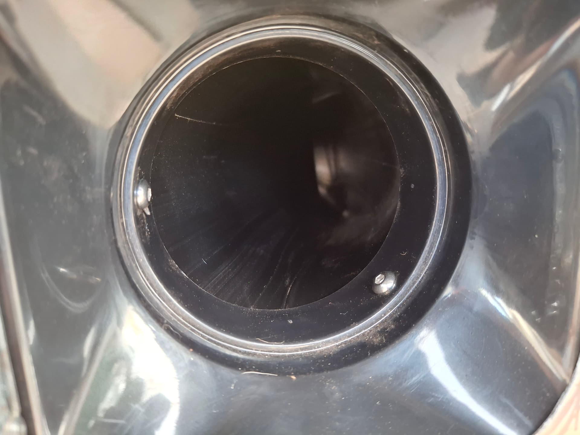
The next consideration was the intake and exhaust of the duct. The duct intake is about 4", and the duct exhaust is about 3". After I didn’t find anything on automotive performance websites that would work with the Barracuda’s valance and a 4" duct, I turned to exploring Amazon. I found ABS clothing dryer wall adapters that could work and took the chance, which turned out to be the correct choice. The 4" dryer connection would serve as the intake, and the 3" dryer connection would serve as a means to direct the exhaust airflow as needed.
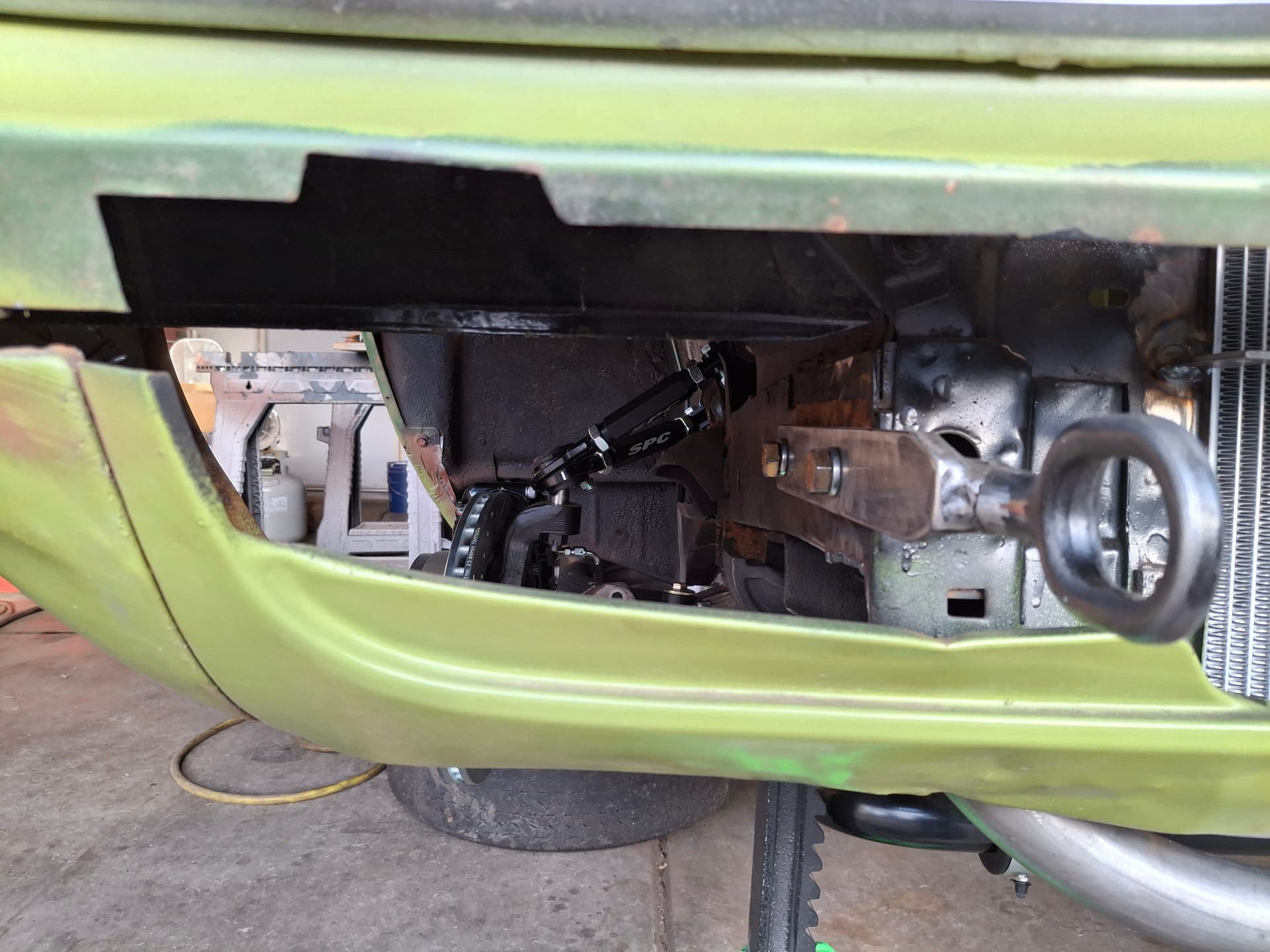
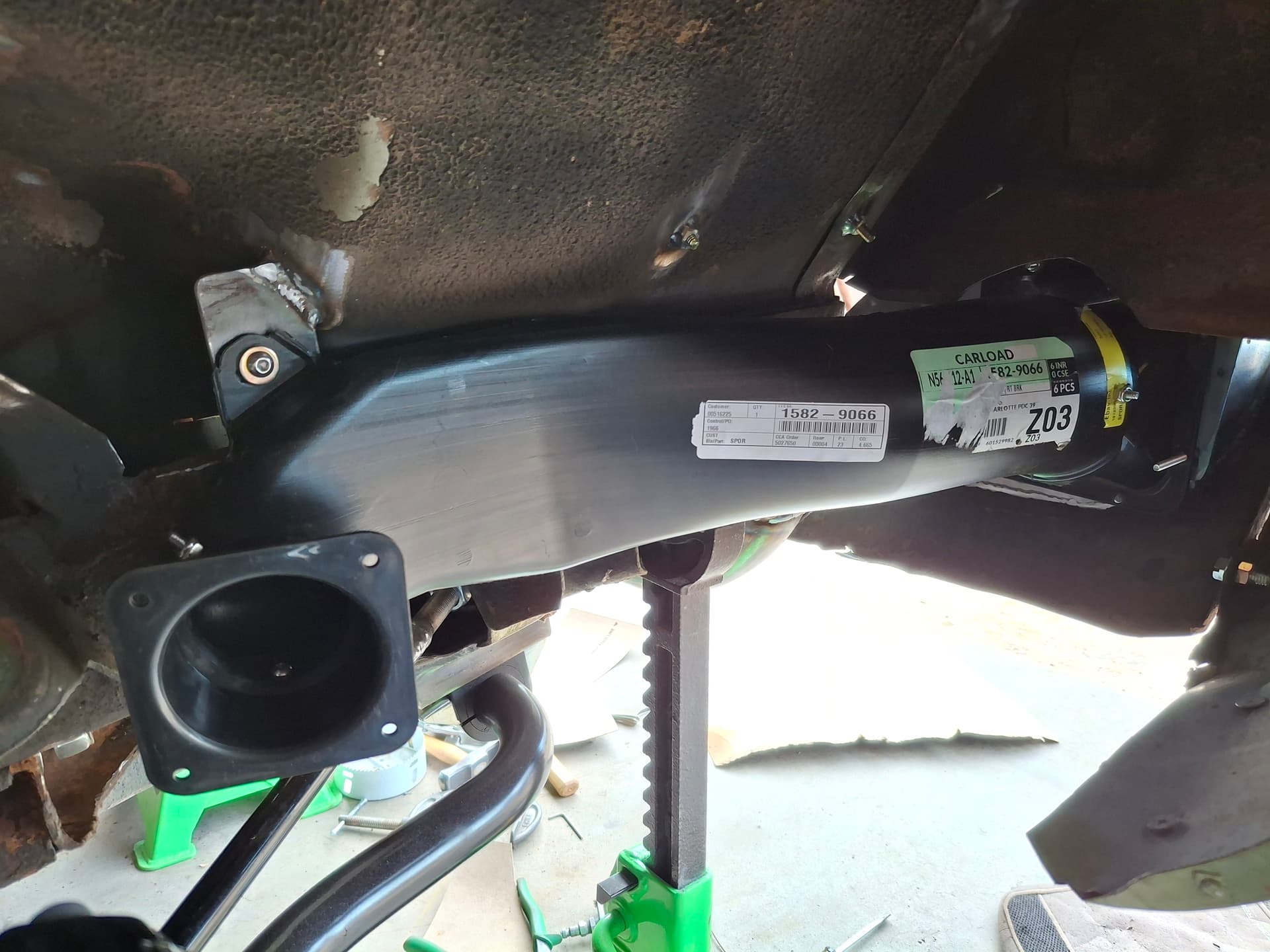
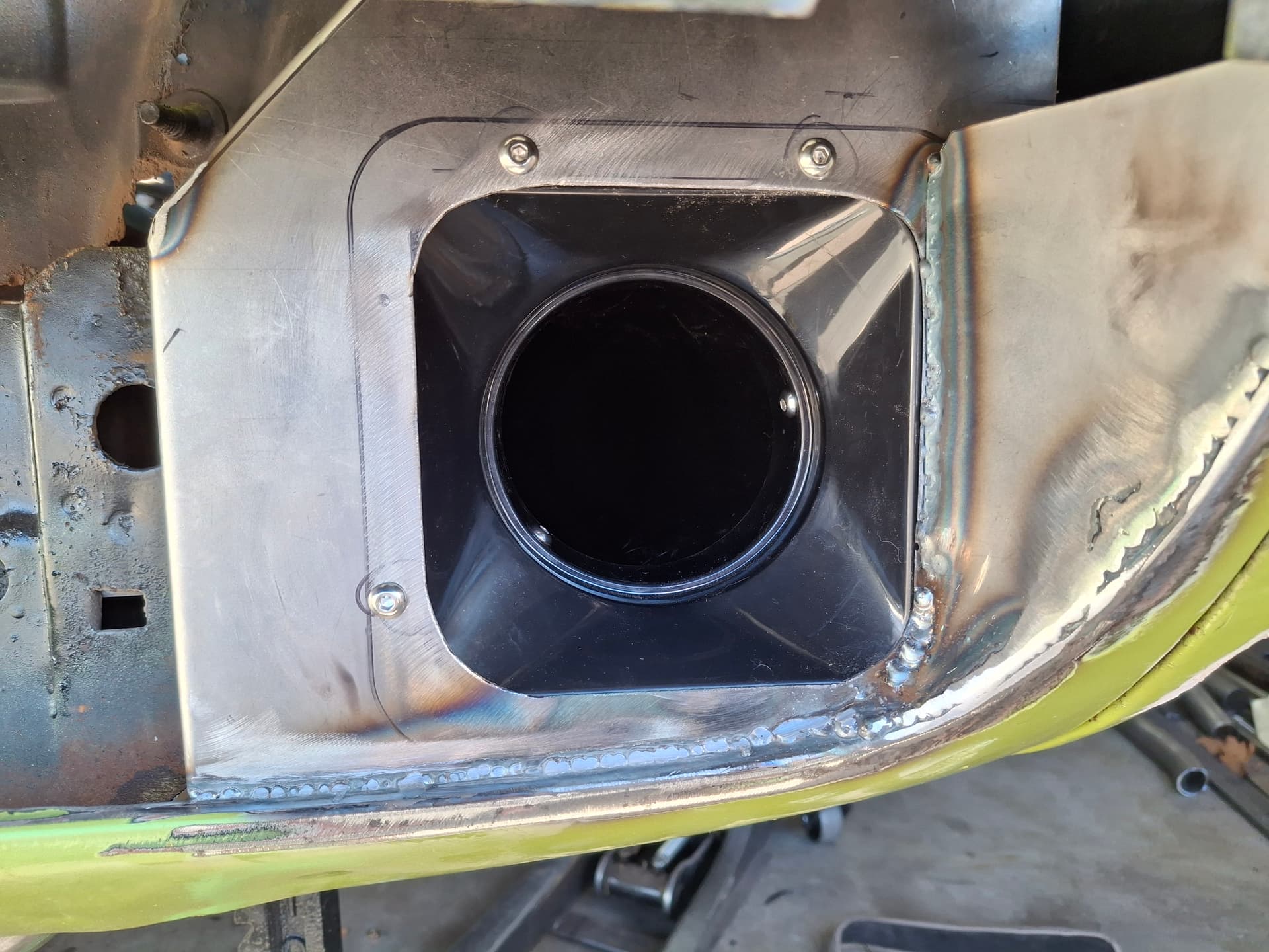
I started by cutting some of the valance opening away to make room and a clearer path for the air. I fabricated mounting panels from 18-gauge sheet metal that break back into the core support to form a shroud blocking air from escaping, forcing it into either the brake duct or the radiator. After welding those panels to the valance, I shaped sheet metal into the sides to shroud the opening. In these photos, I haven’t done the metal finishing bodywork, so the welds will get cleaned up and smoothed out before paint.
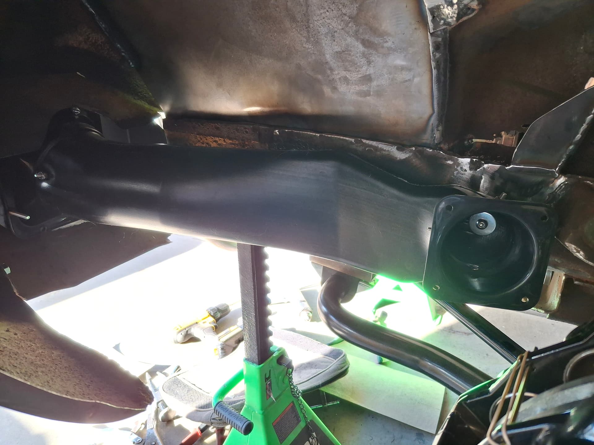
I sculpting the 4" end of the duct for a tight fit to the intake, welded on a mounting tab on the right side (the left didn’t need one), and drilled and tapped the holes. I bolted the duct to the frame rail with 1/4" machine screws and used #10 machine screws to secure the duct to the intake dryer adapter. I sculpted the 3" exhaust opening to angle the airflow toward the caliper and rotor center and secured the dryer vent connection with #10 machine screws.
While I have no idea how functional/beneficial the system will be, I assume it’s better than nothing at all.
Post Alert Pings:
@jonUU
@Sportsracer
@Datsun78
@Bob_Alder
@Rich
@Nick_H
It’s crazy the stuff we hang on to thinking we might need it someday. I have a pair (L&R) from my C6 Z06 sitting in my basement that are yours if still needed. It would appear however that you’ve managed a workaround - nicely done. ![]()
Lol, @jonUU, what are the odds? I would gladly have used those. Now that I’ve cut up the ones I bought and they’re finished, I don’t think I’ll need another set unless mine get damaged.
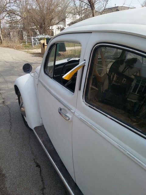
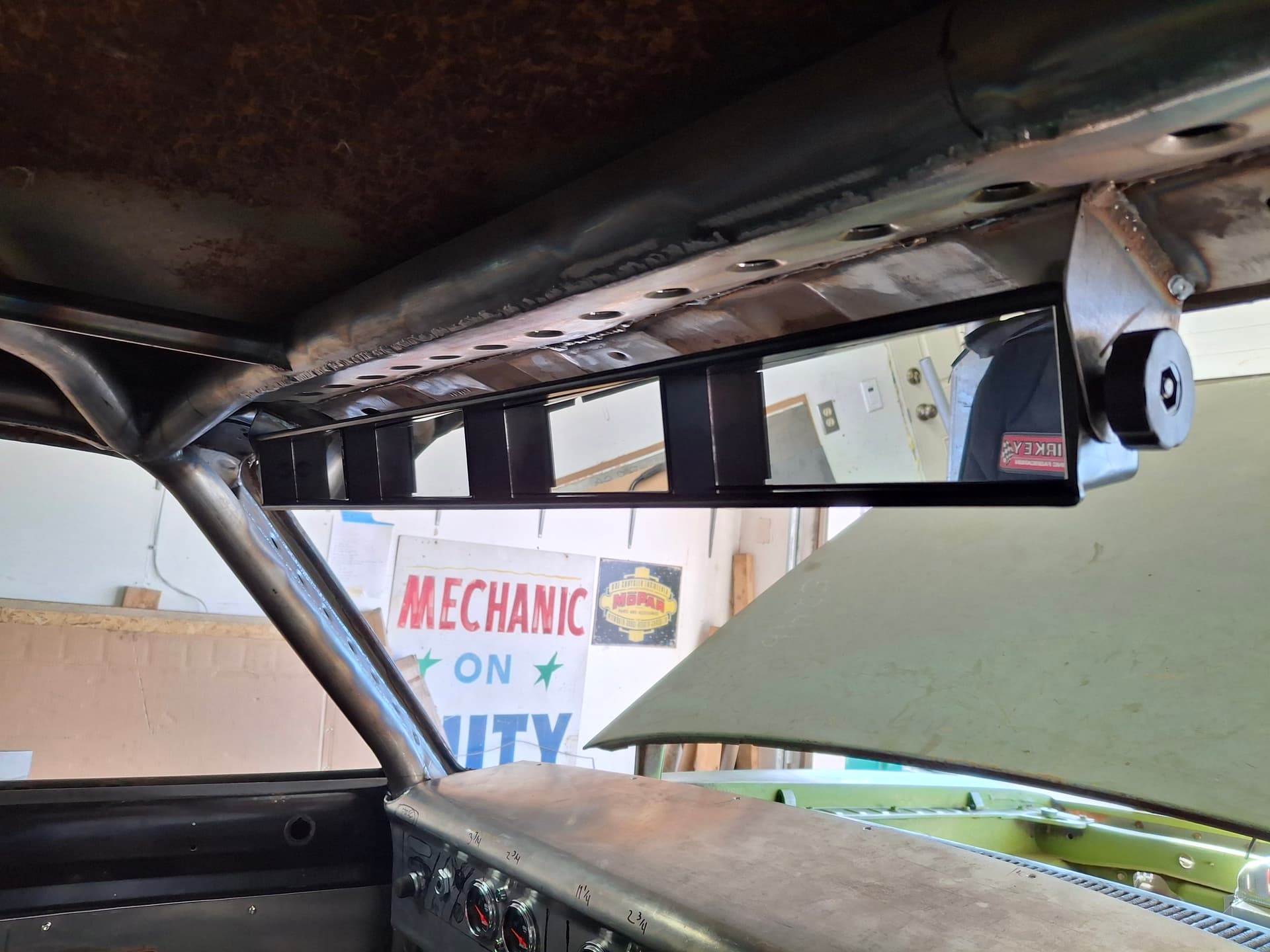
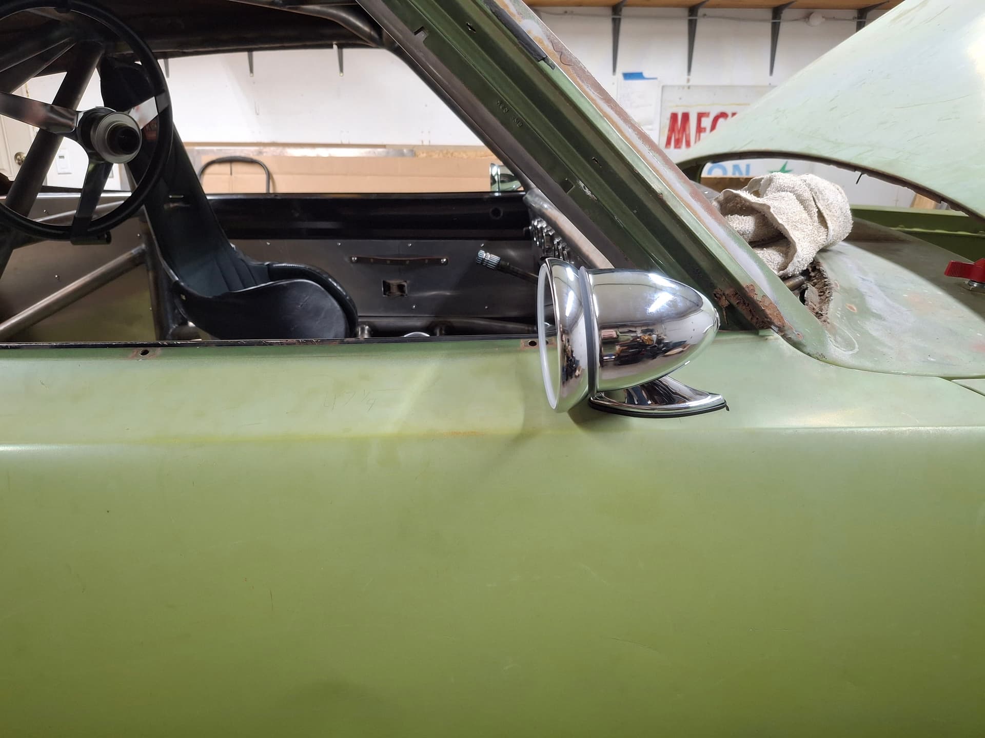
Rear-View Mirrors
I fabricated brackets for and mounted the 28" rear-view mirror. I hate the way these things look, but this is a moment of function over form since the Barracuda has some blind spots that this mirror really helps address. I experimented with different locations for the door mirrors and drilled holes for and mounted GT-style bullet mirrors.
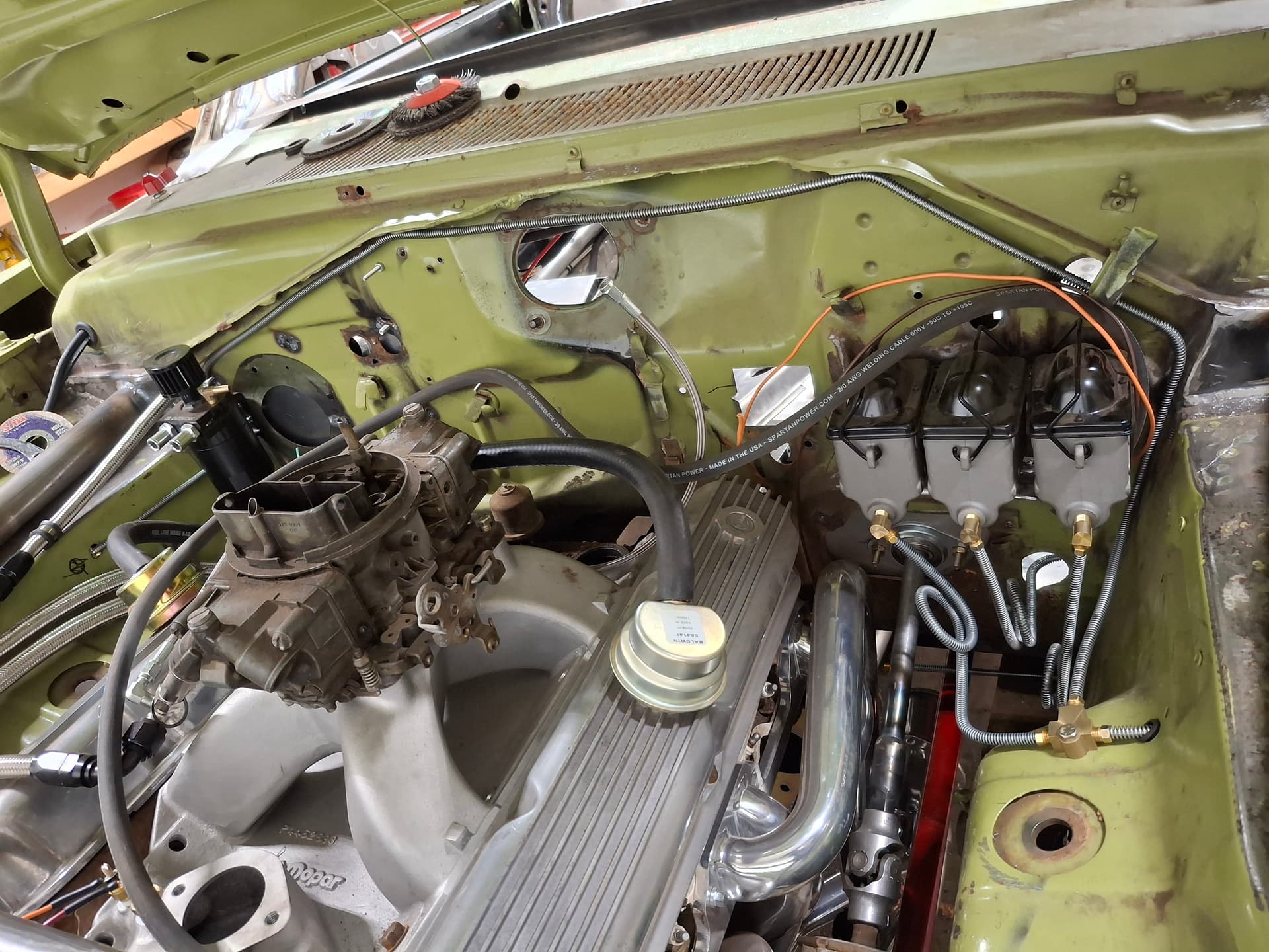
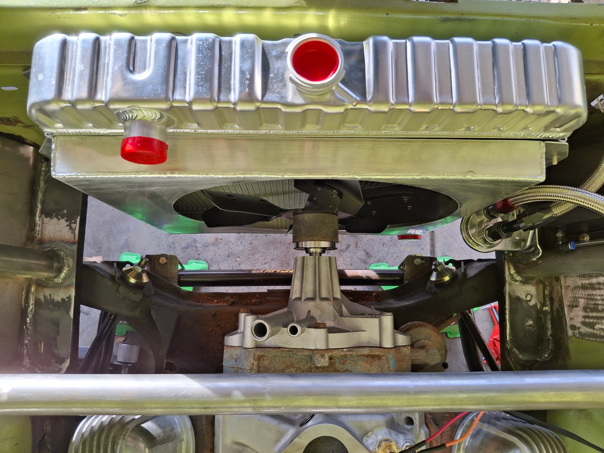
Water Pump
For some historical context, pre-1970 small block water pumps (and their replacements) are cast iron with the inlet on the left/driver side. The impeller shaft is also shorter. In 1970, Mopar switched to an aluminum pump with a longer impeller shaft and the inlet on the right/passenger side. To take advantage of the aluminum for weight saving, I mocked up a 1970 water pump and will obtain the correct crank and pump pulleys when I get that far.
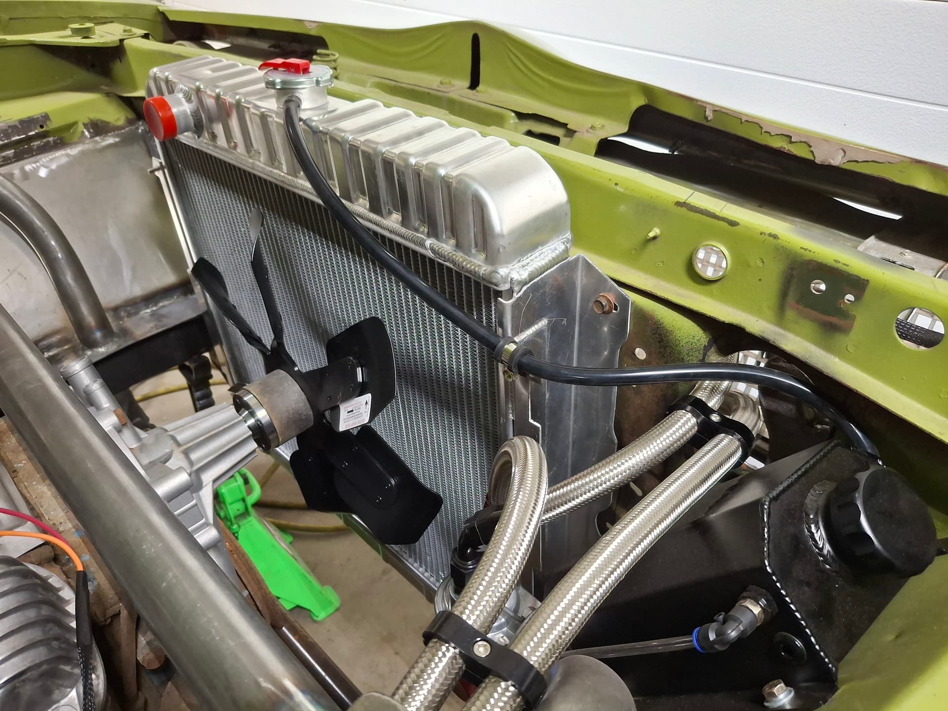
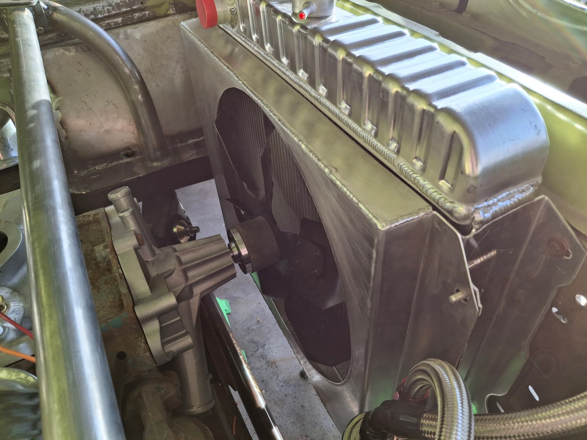
Radiator, Fan, and Shroud
The radiator is an extra-wide two-row aluminum unit designed for 1970+ (for the right/passenger exit) big block B-body Dodge/Plymouth cars with stamped tanks for that OEM look, once painted. I had to drill/elongate new holes in the radiator flange to mount it, and it bolts to the core support with 1/8"-thick rubber washers for vibration dampening and to help reduce the protentional for galvanic corrosion.
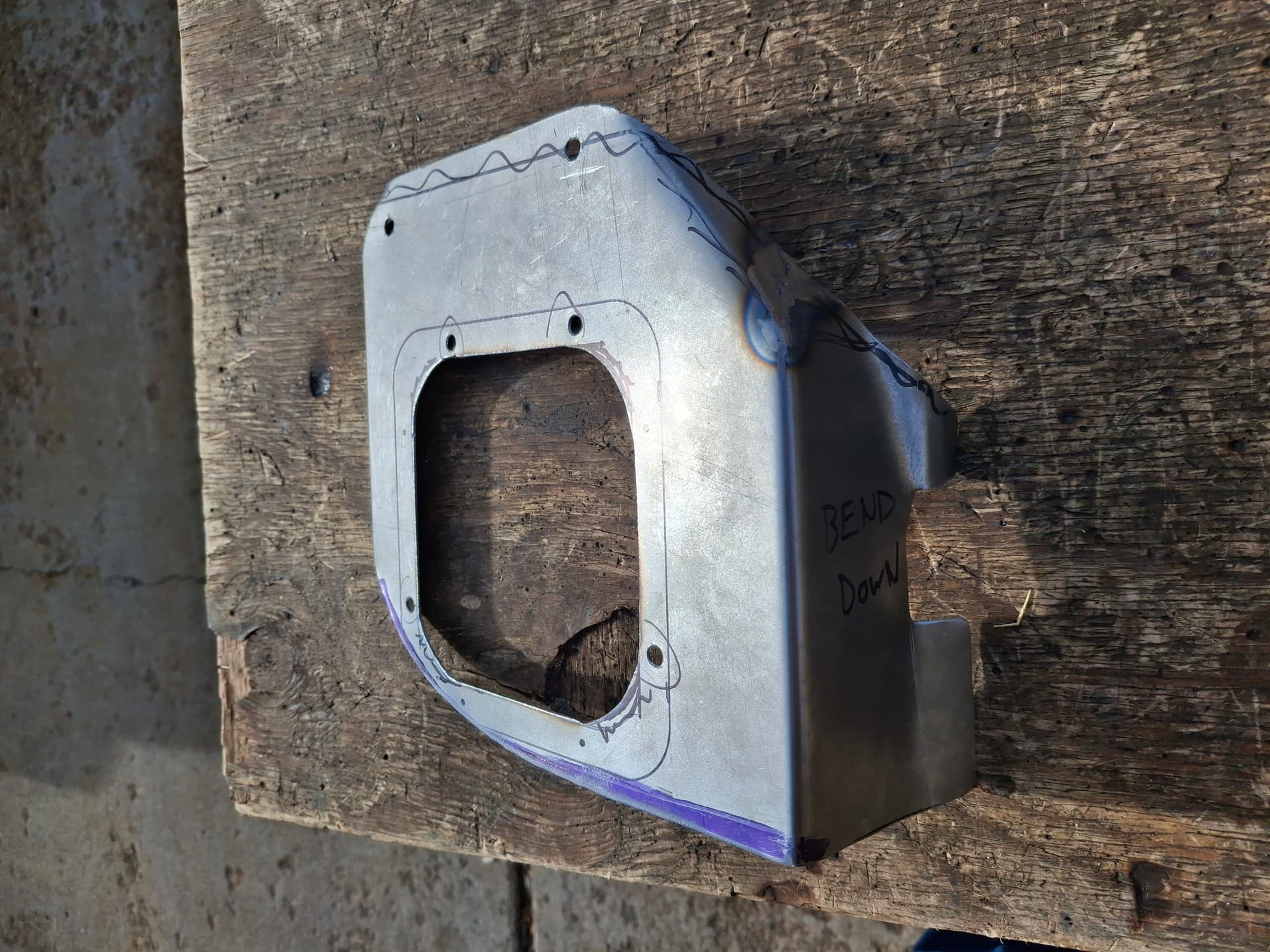
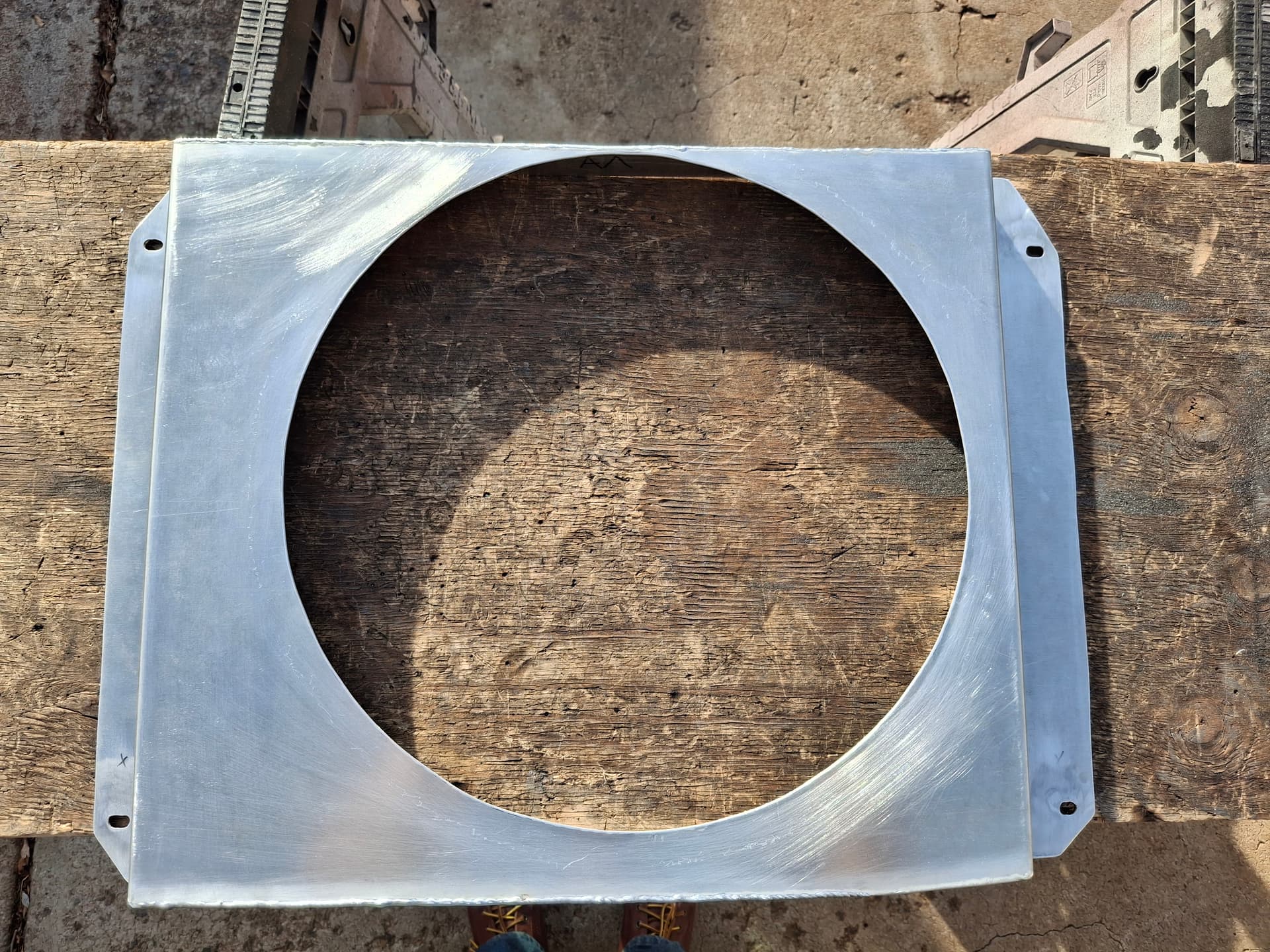
Before anyone jumps on me ![]() , I’m aware that it is highly, highly unlikely I will need a shroud at track speeds for proper cooling and that the shroud may actually harm cooling and create unnecessary drag on the car. However, I want to be ready to test a shroud if needed, and I want to have one on hand if I find that I need it on the street for those RMVR-promotion cars and coffee/cruise gatherings. For these reasons, I designed and fabricated a shroud that easily installs onto four studs welded into the radiator flange. I fabricated the shroud from aluminum sheet bent on the work bench.
, I’m aware that it is highly, highly unlikely I will need a shroud at track speeds for proper cooling and that the shroud may actually harm cooling and create unnecessary drag on the car. However, I want to be ready to test a shroud if needed, and I want to have one on hand if I find that I need it on the street for those RMVR-promotion cars and coffee/cruise gatherings. For these reasons, I designed and fabricated a shroud that easily installs onto four studs welded into the radiator flange. I fabricated the shroud from aluminum sheet bent on the work bench.
For the fan, I’m experimenting with a 15" diameter that has a steel center and six fixed (i.e. non-flex) aluminum blades for a vintage look. A 17" fan will fit without a shroud, but I’d like to reduce rotating mass and drag while keeping a vintage appearance. I have a factory steel 17" six-blade fan I’ll bring to test and tune in the event the 15" isn’t cooling enough, and I can get a 17" aluminum version of this 15" fan if I find the engine needs it.
Post Alert Pings:
@jonUU
@Sportsracer
@Datsun78
@Bob_Alder
@Rich
@Nick_H
1 Like
Hi Justin
Not digging on you but a few lessons that I learned from my v8 Miata conversion.
-Reducing the area of the air intake to the radiator is very beneficial. ( the formula is the area of the intake opening should be 1/3 the area of the total radiator surface)
- slowing the air flow through the radiator helps allow heat transfer
- The shroud may help by slowing the air flow.
- sealing the radiator edges to the body to make sure all the intake air goes through the radiator is paramount
Not saying you shouldn’t try out all the options, but I’ve “around the horn” so to speak with cooling on V8’s in small cars.
Love you build and the fabrication looks top shelf. Enjoy the journey!
Best
Tom
Thanks for the input, Tom @Sportsracer. I am planning on welding up all unnecessary holes in the core support and making the necessary ones as small as possible. I am also planning on using rubber weatherstrip of some sort atop the core support to seal against the hood as best as possible (I thought maybe the bottom seal of a garage door? if I can’t find automotive long and puffy enough).
I hadn’t heard of the 1/3 reduction of the opening you mention, so I’m curious. If that’s the case, the shroud may very well help since it’s reducing the surface area but just on the backside. This is something we can discuss and brainstorm when you visit in the new year. I appreciate your input.