Project Cuda: Building a 1969 Plymouth Barracuda Big Bore Car

Happy New Year!

Intake Manifold
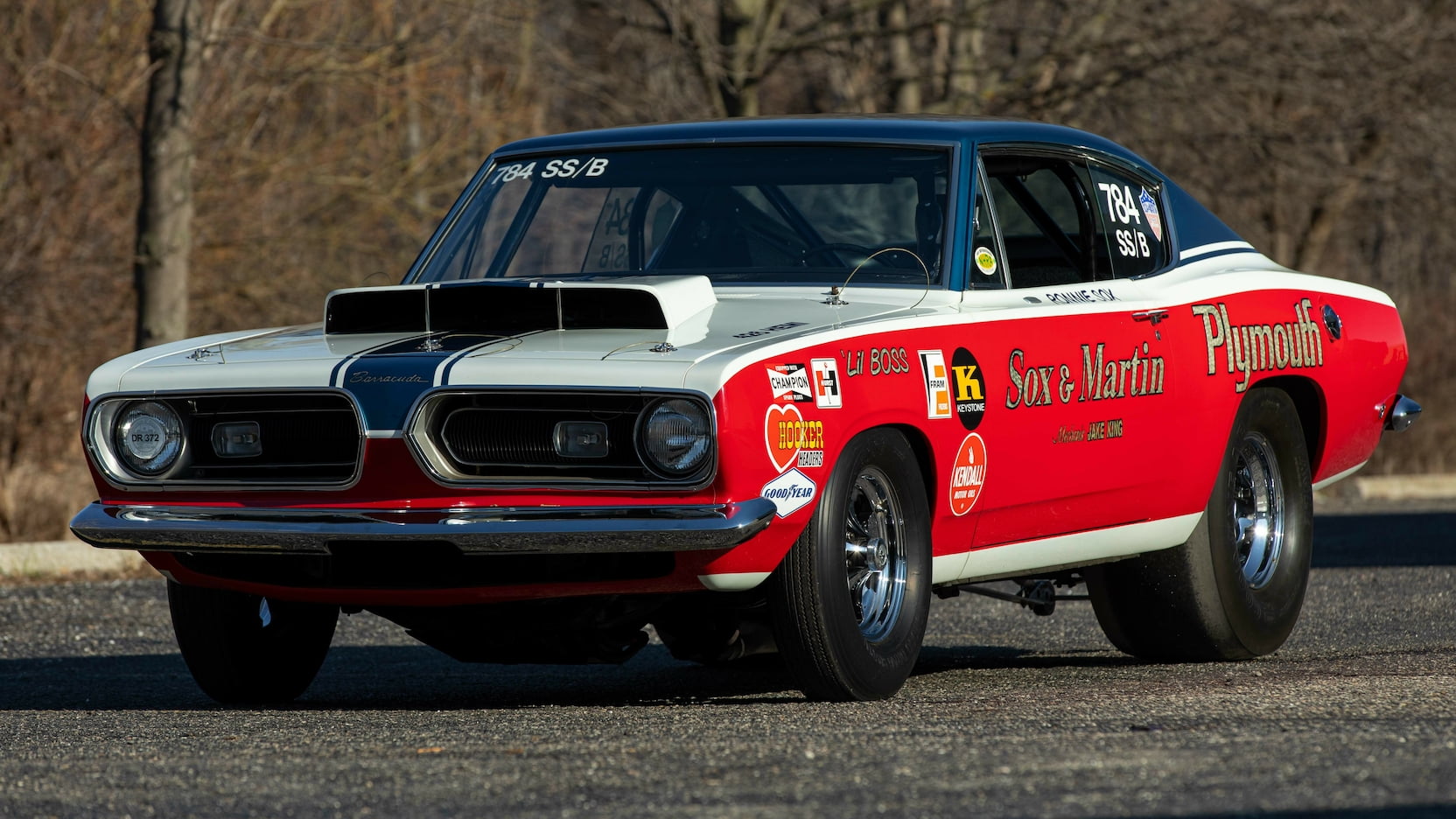
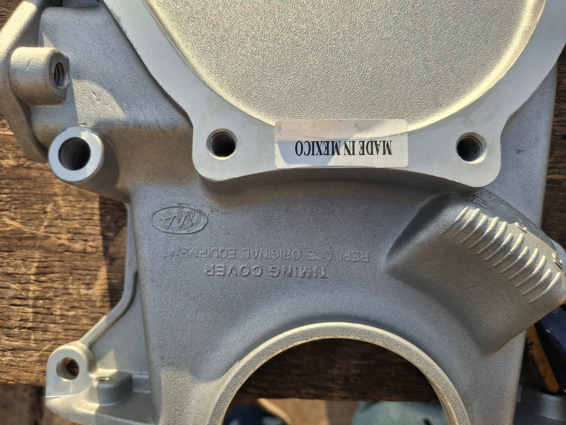
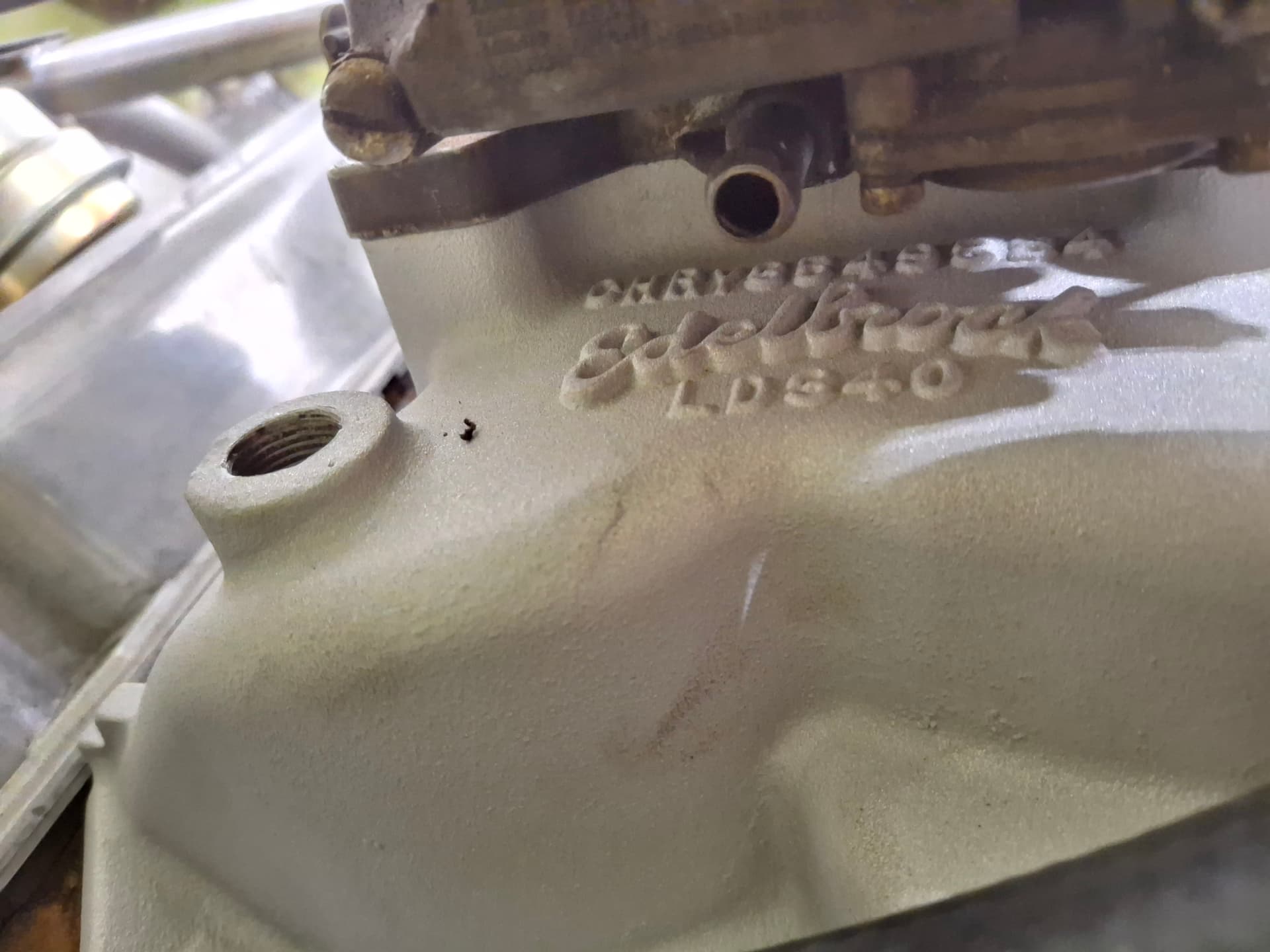
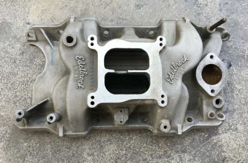
For historical context, from what I have read and been told through hot-rodding lore, in 1969 Mopar wanted to gain an edge over Chevy and Ford in the induction department for stock racing classes largely in drag racing and oval track where class rules required a factory intake manifold. At the time, Mopar’s best small-block intake was a cast-iron, single four-barrel, dual-plane designed for and used on the 340 starting in 1968. To meet the racing factory requirement, Mopar collaborated with Edelbrock to design and manufacture an aluminum, high-rise, dual-plane, large-runner intake with a cast Chrysler part number that came standard on high-performance 340 engines and optional through the dealership. Thus, the Edelbrock LD340 was born bearing the part number CHRY3549884. According to those who have both bench flowed and dyno tested dual-plane intakes, the LD340 actually outperforms the 1990’s Edelbrock Performer RPM and is bettered only by the modern Edelbrock Air Gap on 340 and higher displacements. LD340s are not impossible to find, but they are getting rare in good condition. I happen to have come across and purchased one a few years ago that has been waiting for an engine. While subjective, I think it is one of the best-looking single-carburetor intakes ever made with very cool runner shapes. The fact Chrysler worked with Edelbrock to meet racing specs and that the intake bears a factory part number just adds to the intake’s appeal. As an aside, Mopar and Edelbrock used the lessons learned from the LD340 when they created the six-pack intake used on Dan Gurney’s and Swede Savage’s 1970 T/A Barracudas and Sam Posey’s 1970 T/A Challenger. Now that would be a period-correct intake, but it would also cost me about $5,000 for the intake and carburetors.

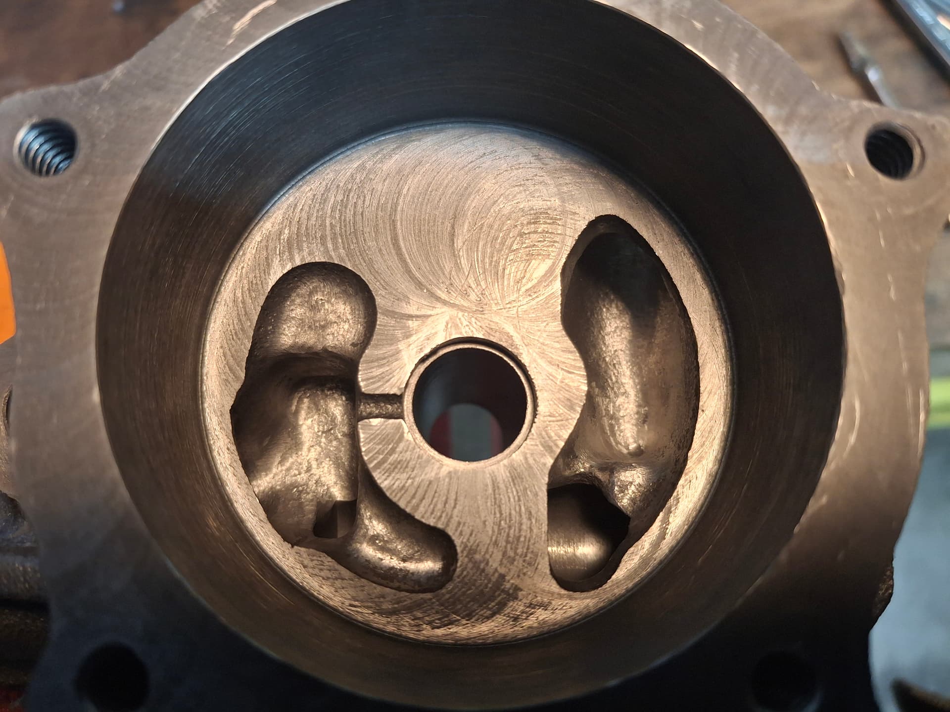
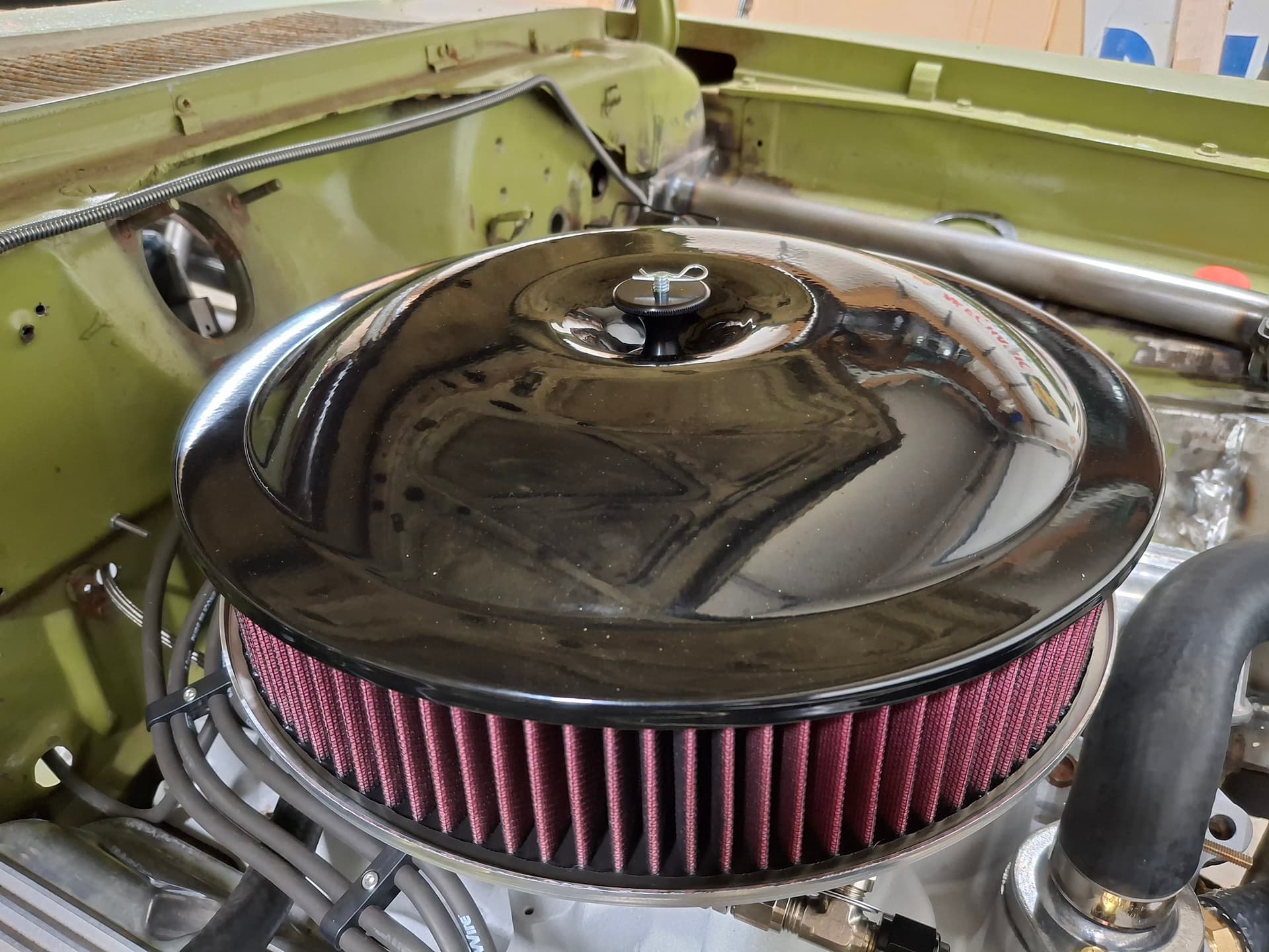
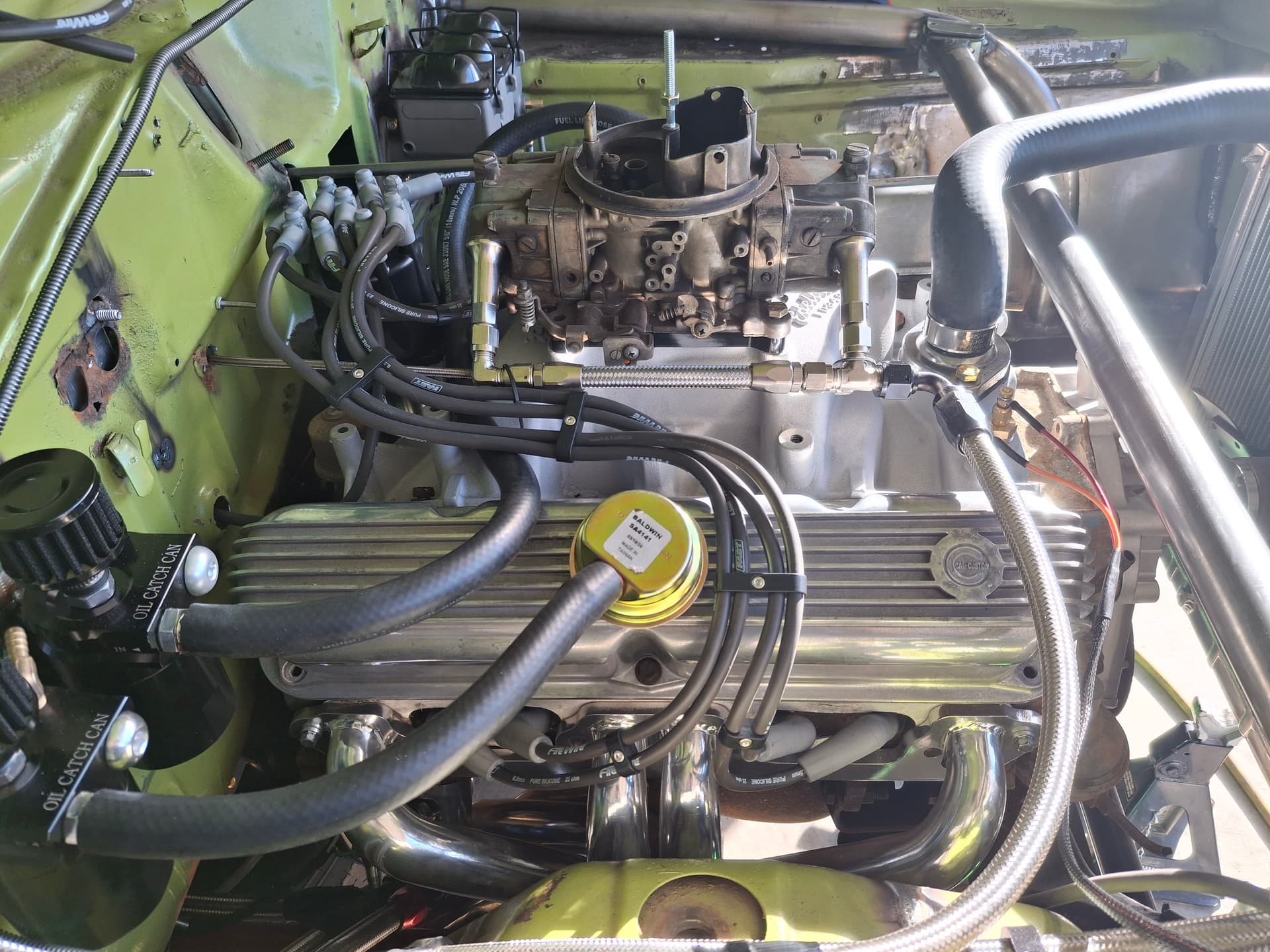
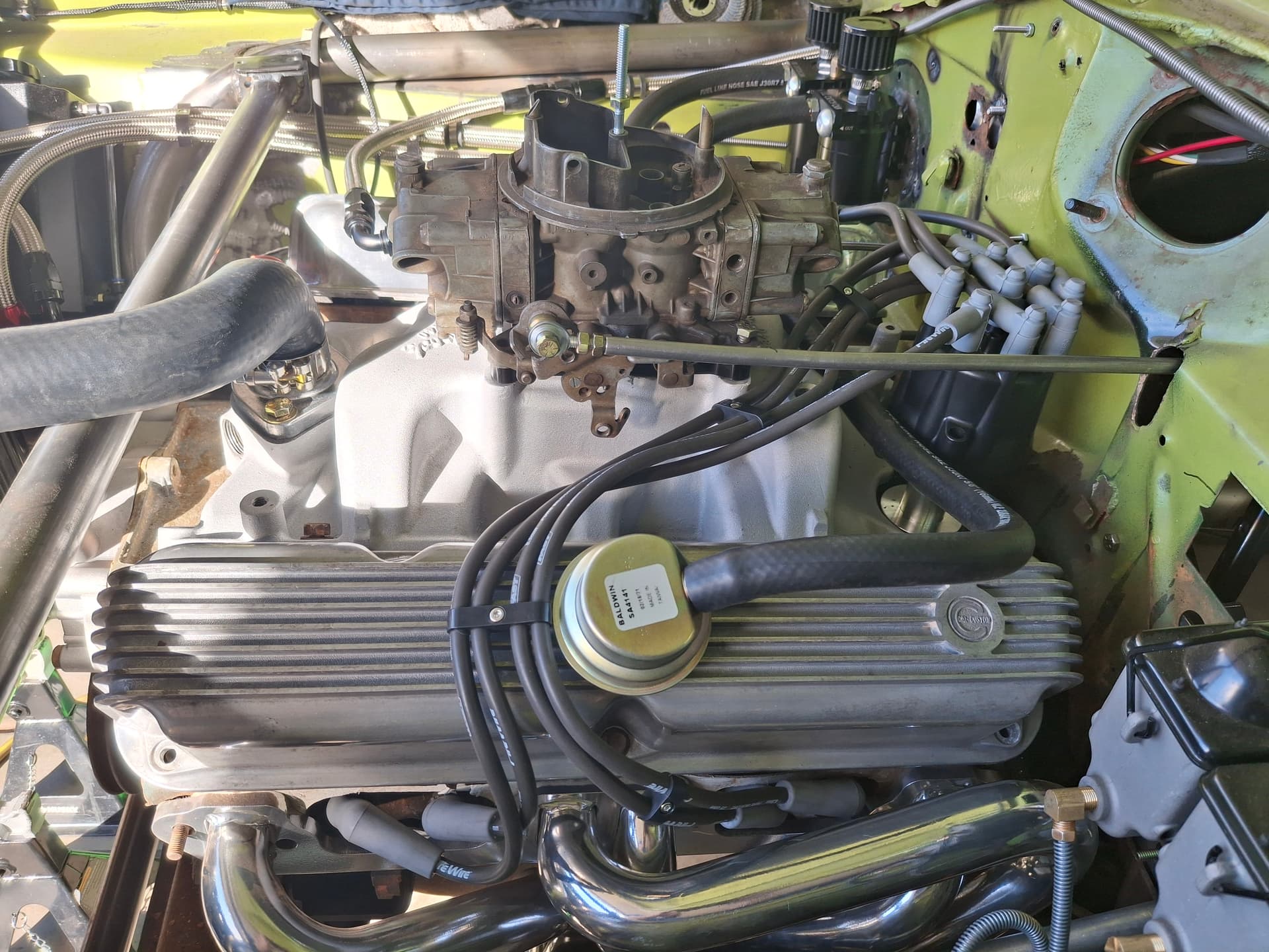
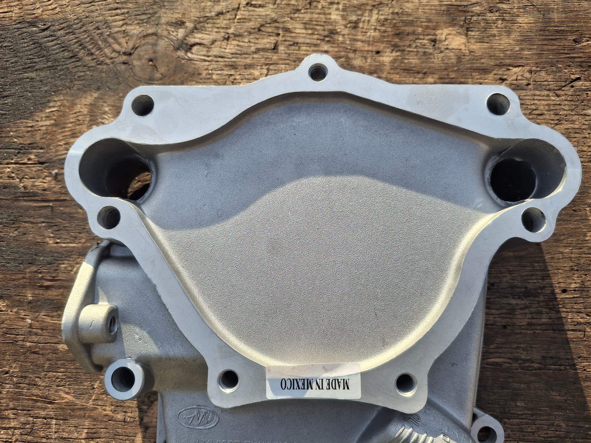
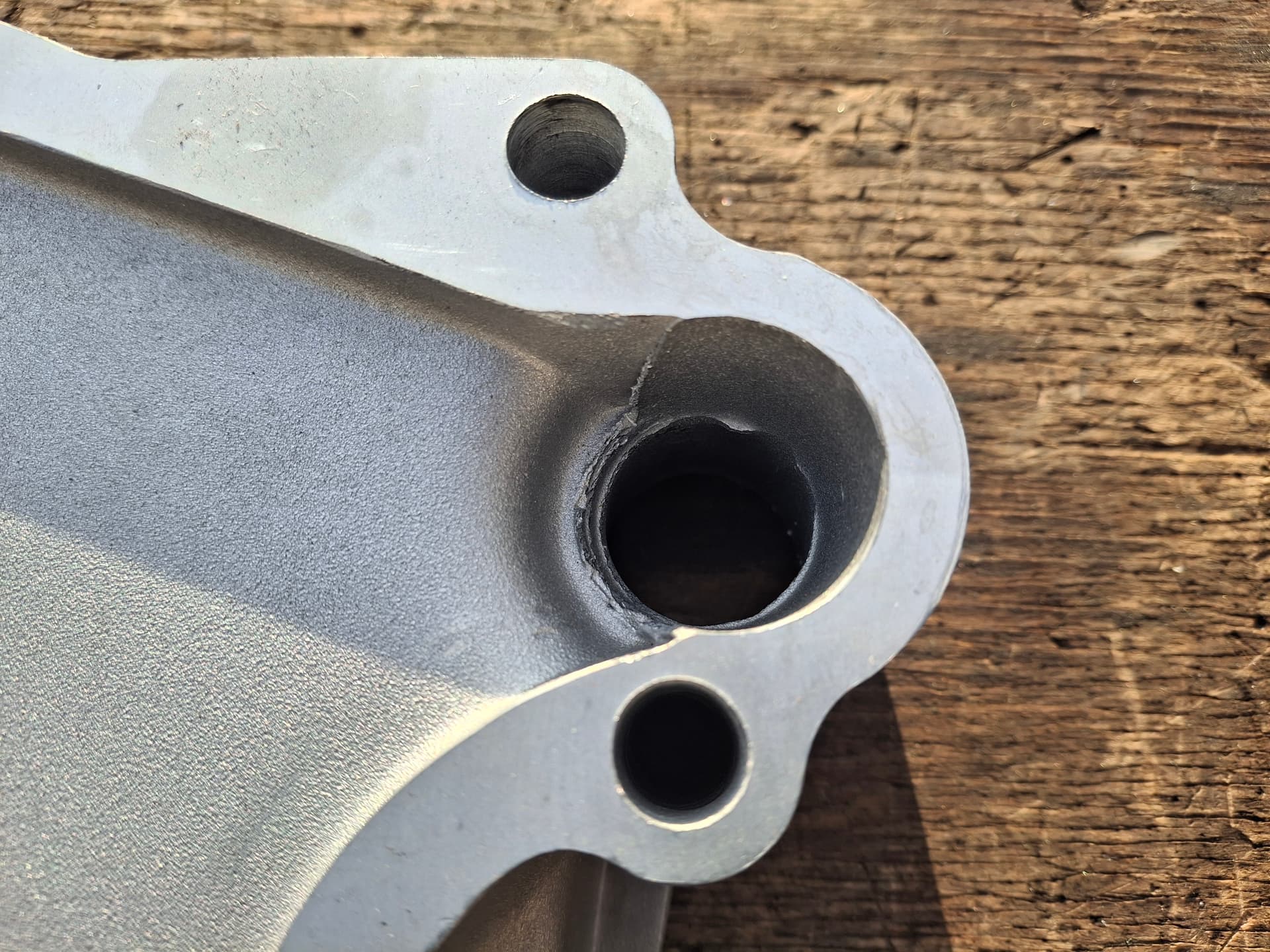
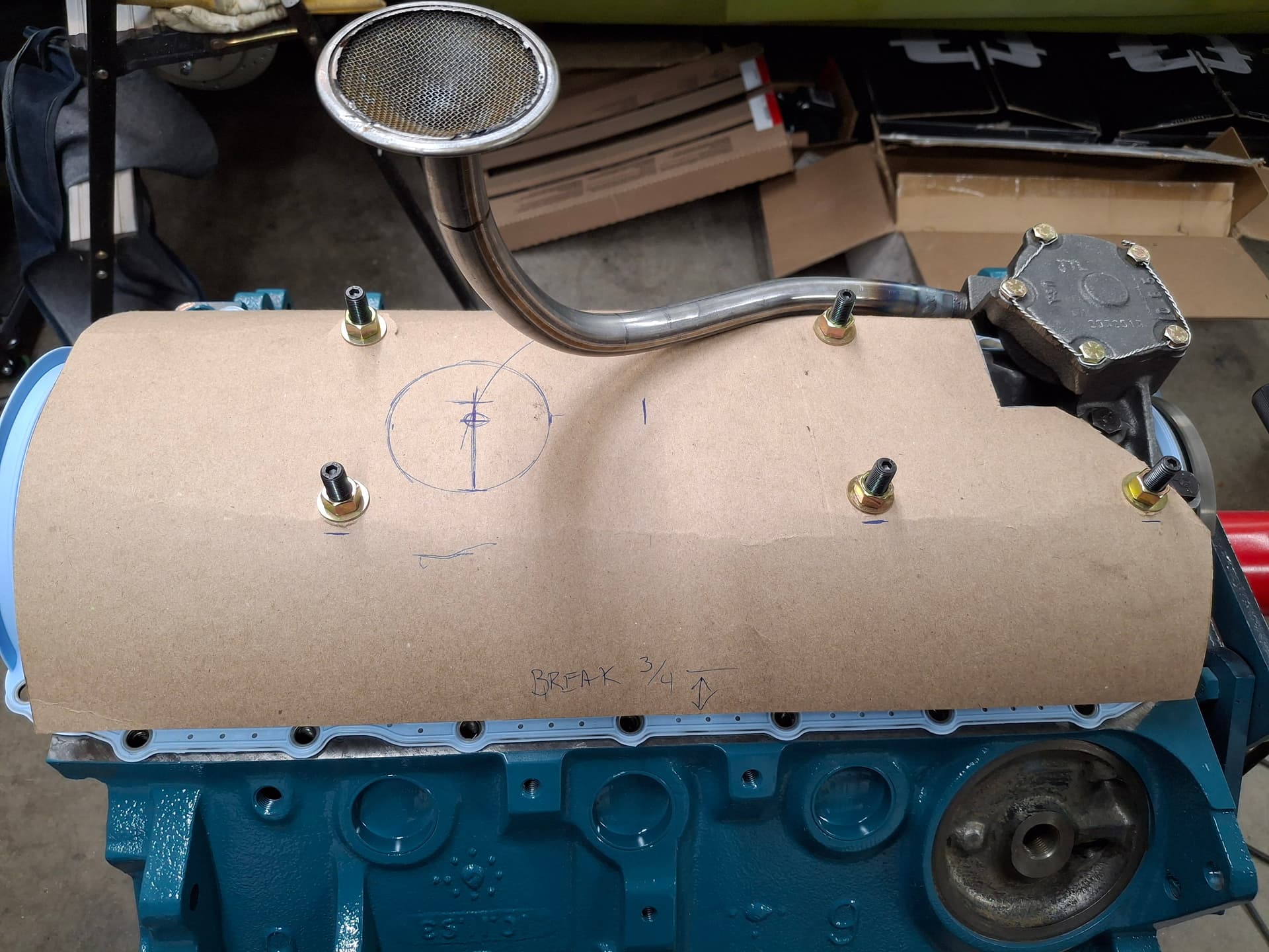
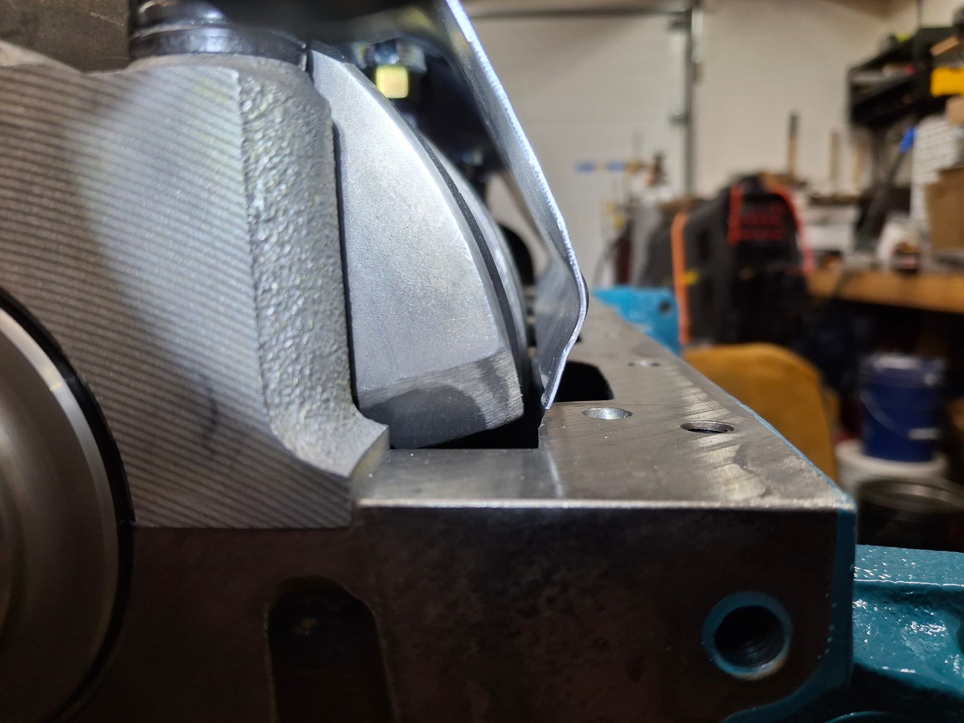
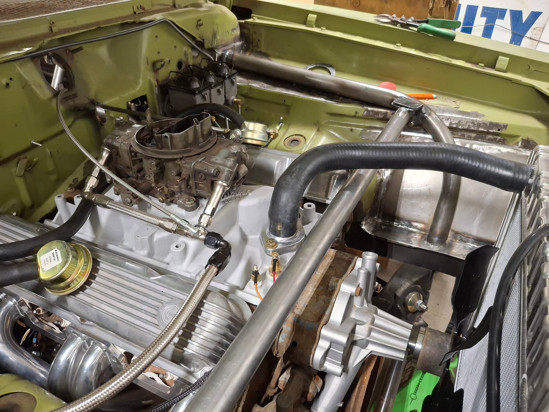
I have had too many internal debates in my head and discussions with others about which intake I should run on the Barracuda’s 364 engine. Keep in mind that the 1981 GT-1 rules do not restrict the intake, so, technically, I can run any single-carburetor intake I want that fits under the hood. On one hand, a dual plane will provide better throttle response and power under 6,000 RPM, while a single plane will provide better power above 6,000 RPM at he loss of some low/mid power and throttle response. On the other hand is period correctness. The most period-correct intake would be the LD340, which you would have seen on cars in 1969, but it’s a dual plane. The other option I have that you’ve seen in previous photos is one of the best single-plane intakes ever designed for a 340/360 small-block Mopar–the “M1” produced by Mopar Performance starting in the early 1990s. The only period-correct single-plane option is the Edelbrock Torker 340 “tarantula” that was available through Edelbrock in 1969, but it is a notoriously power-killing, garbage intake that was produced as eye candy at the expense of performance. So many variables, but I’ve decided to go with the LD340 . . . for now. I figure that the engine will spend far more time under 6,000 RPM (my shifts will be in the 6,500 - 7,000 range), I will want great throttle response, and the period-correctness is important to me. Once I have plenty of track time on this setup for some baseline lap times, I will likely install the M1 just to see how it compares. Feast your eyes on the LD340 (the plenum divider notch is an original design):

Engine Breather System
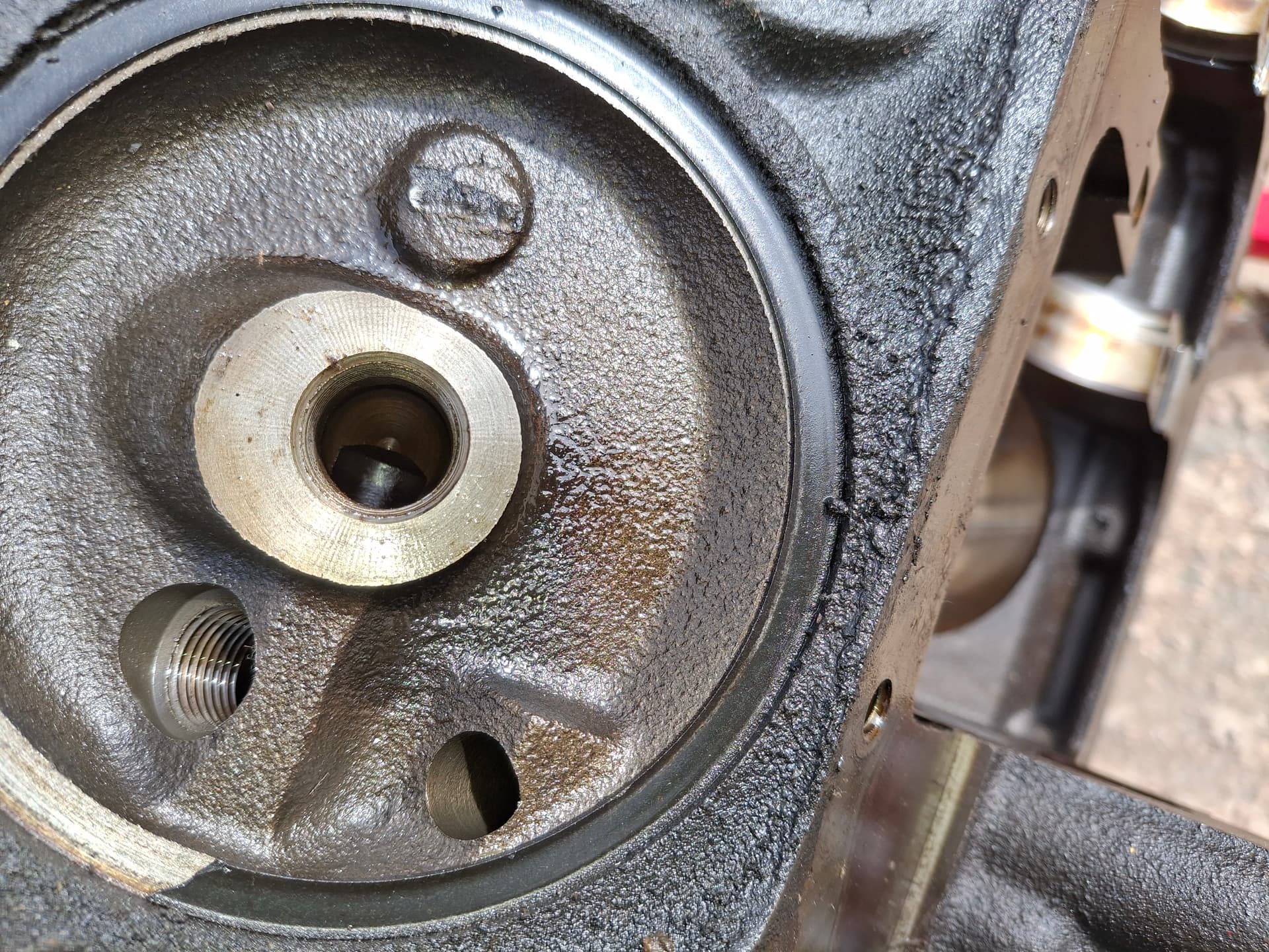
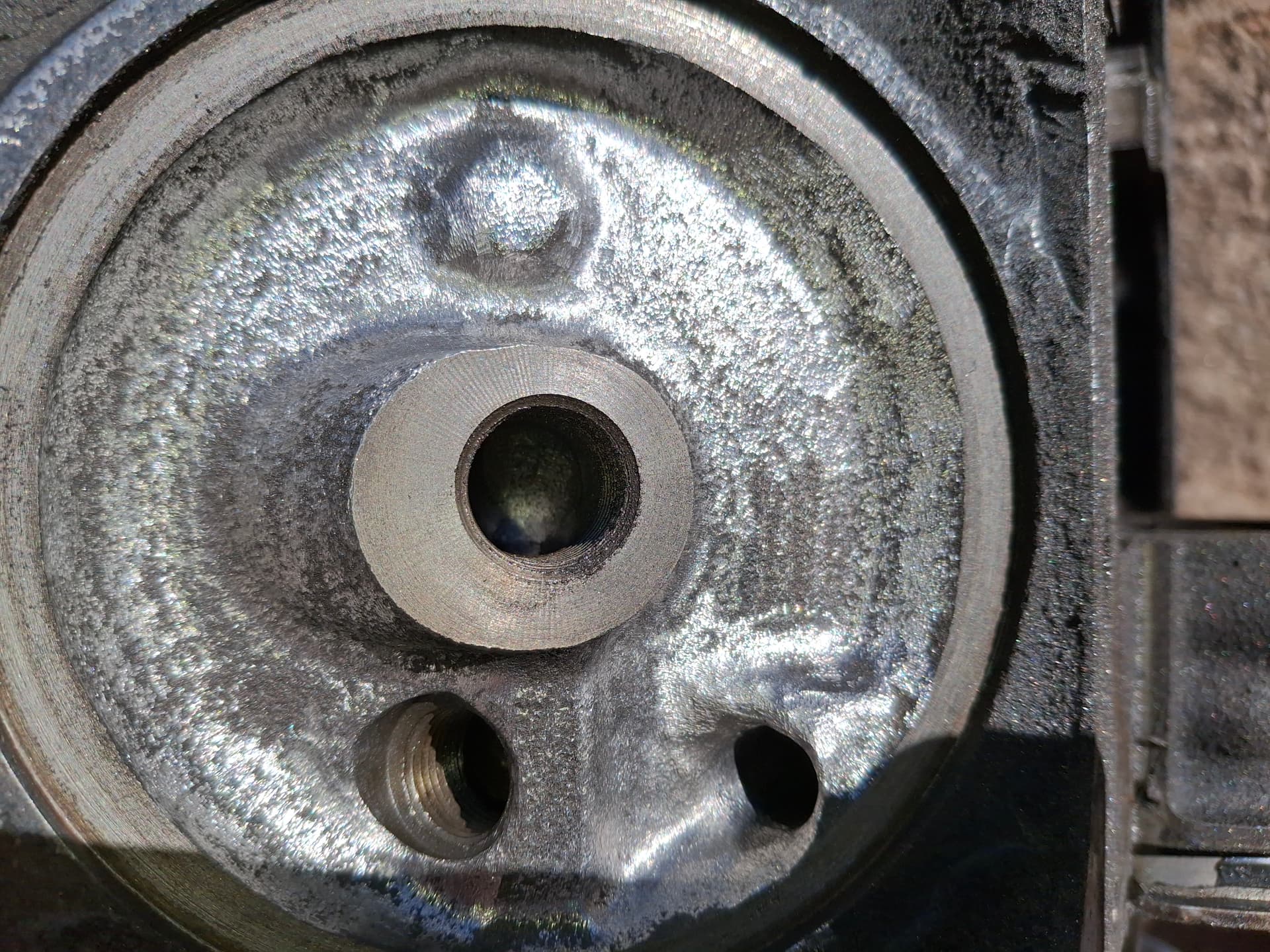
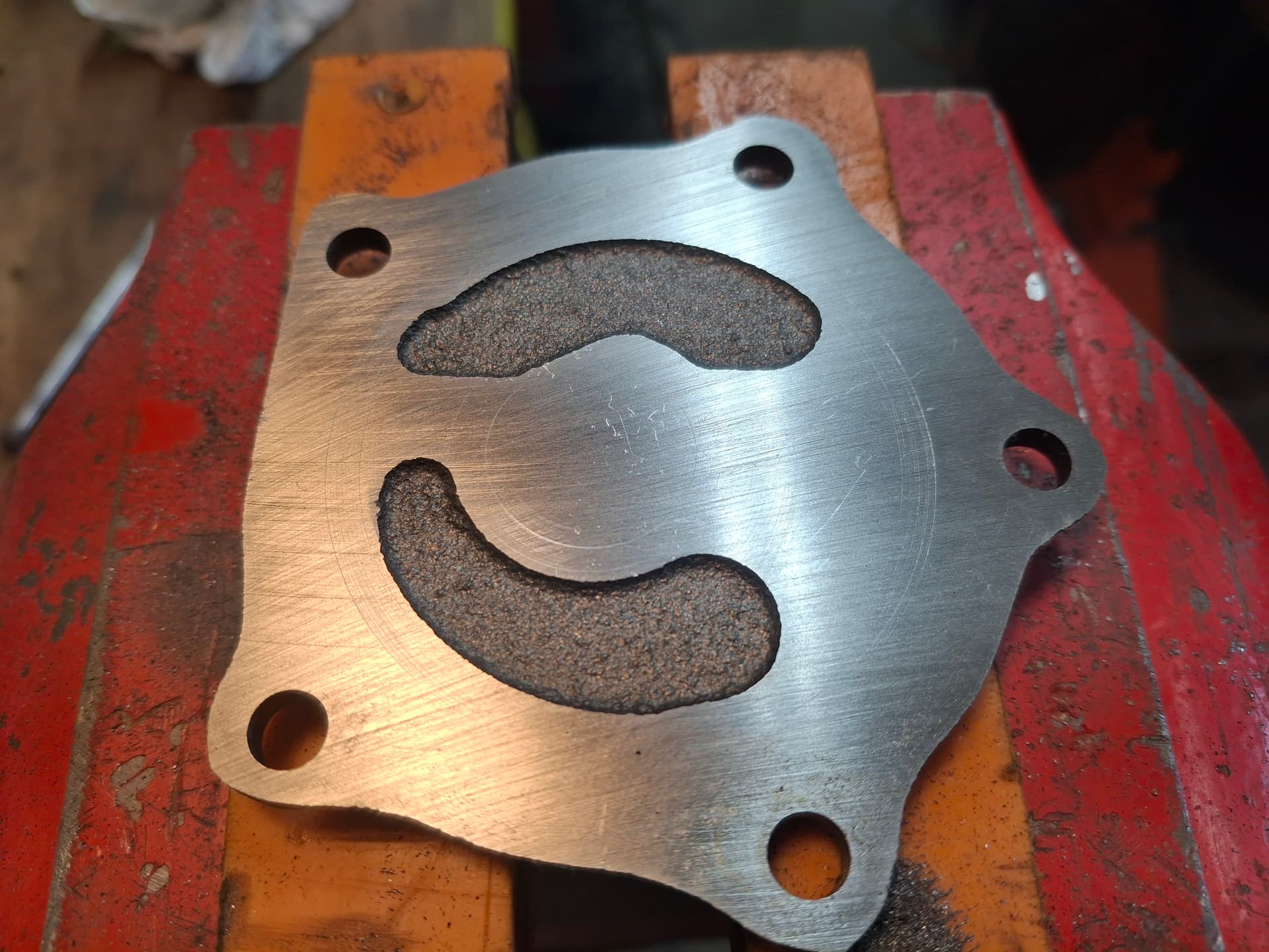
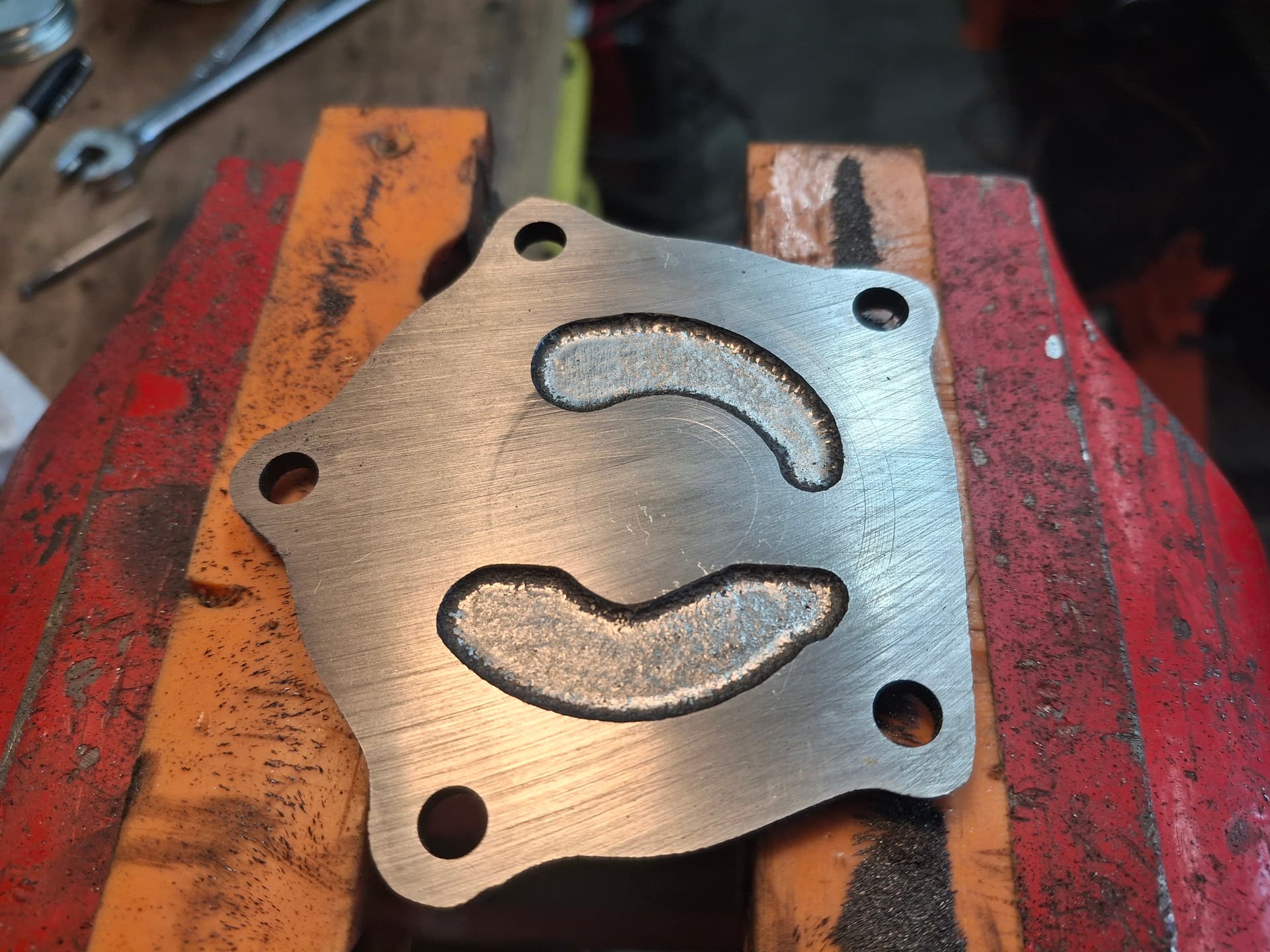
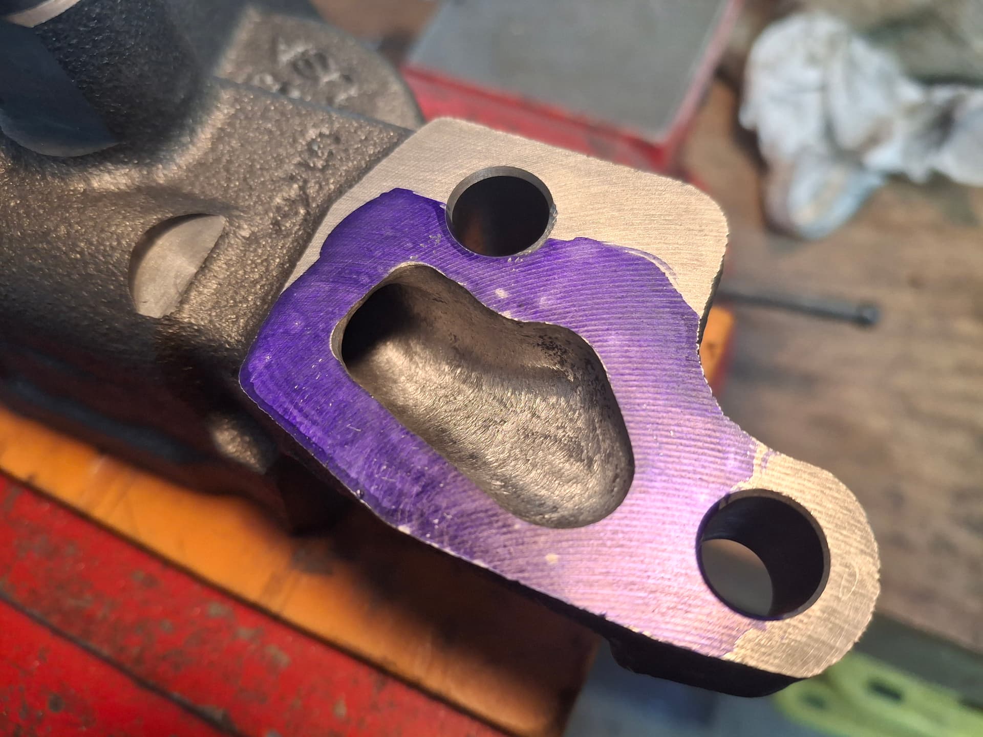
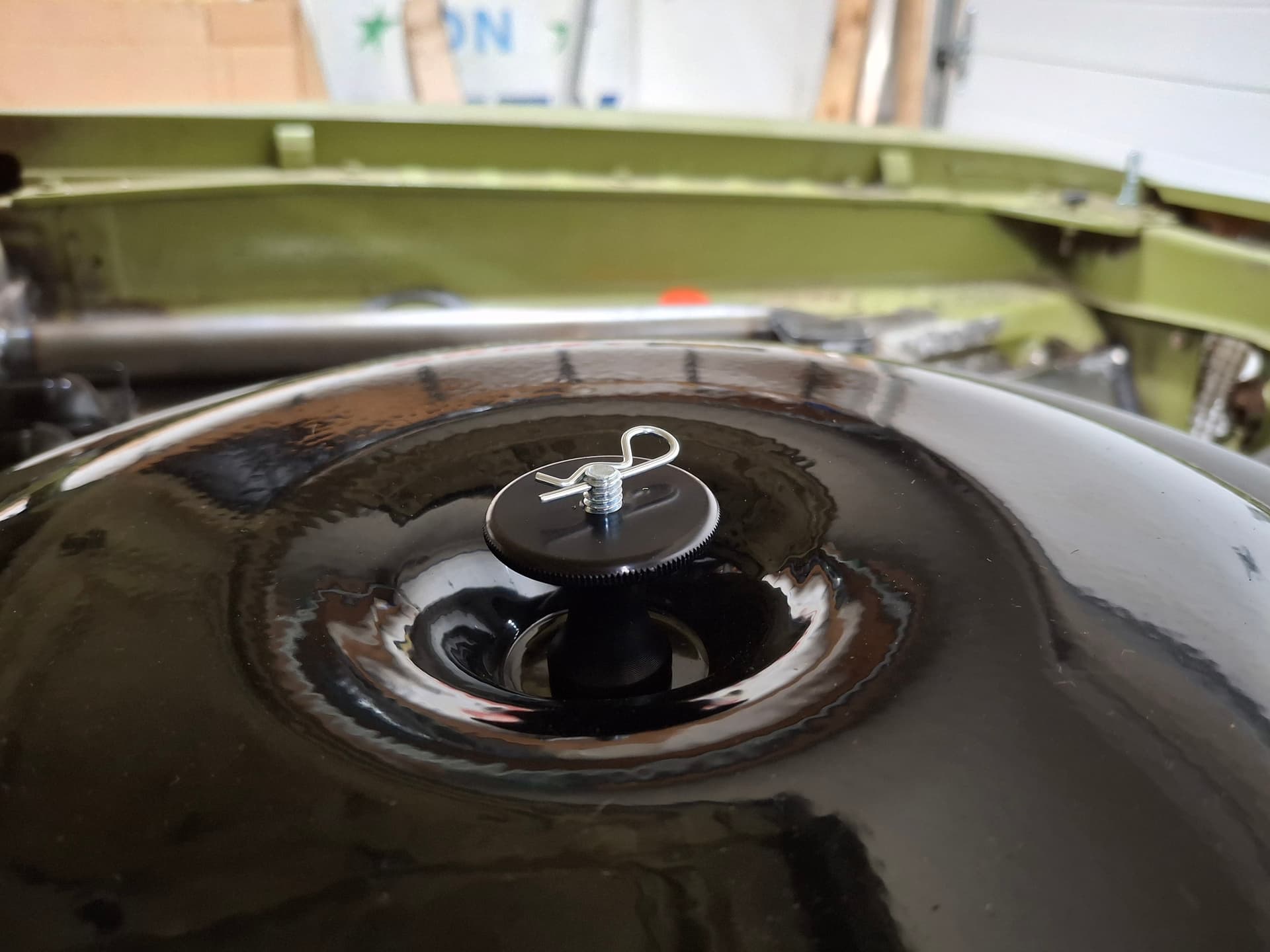
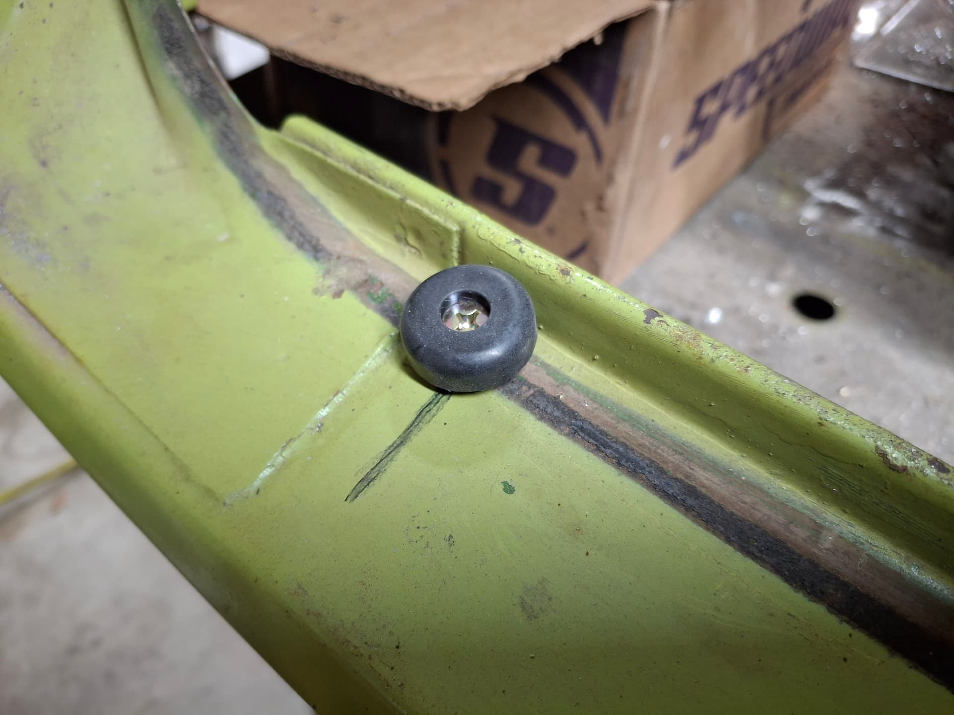
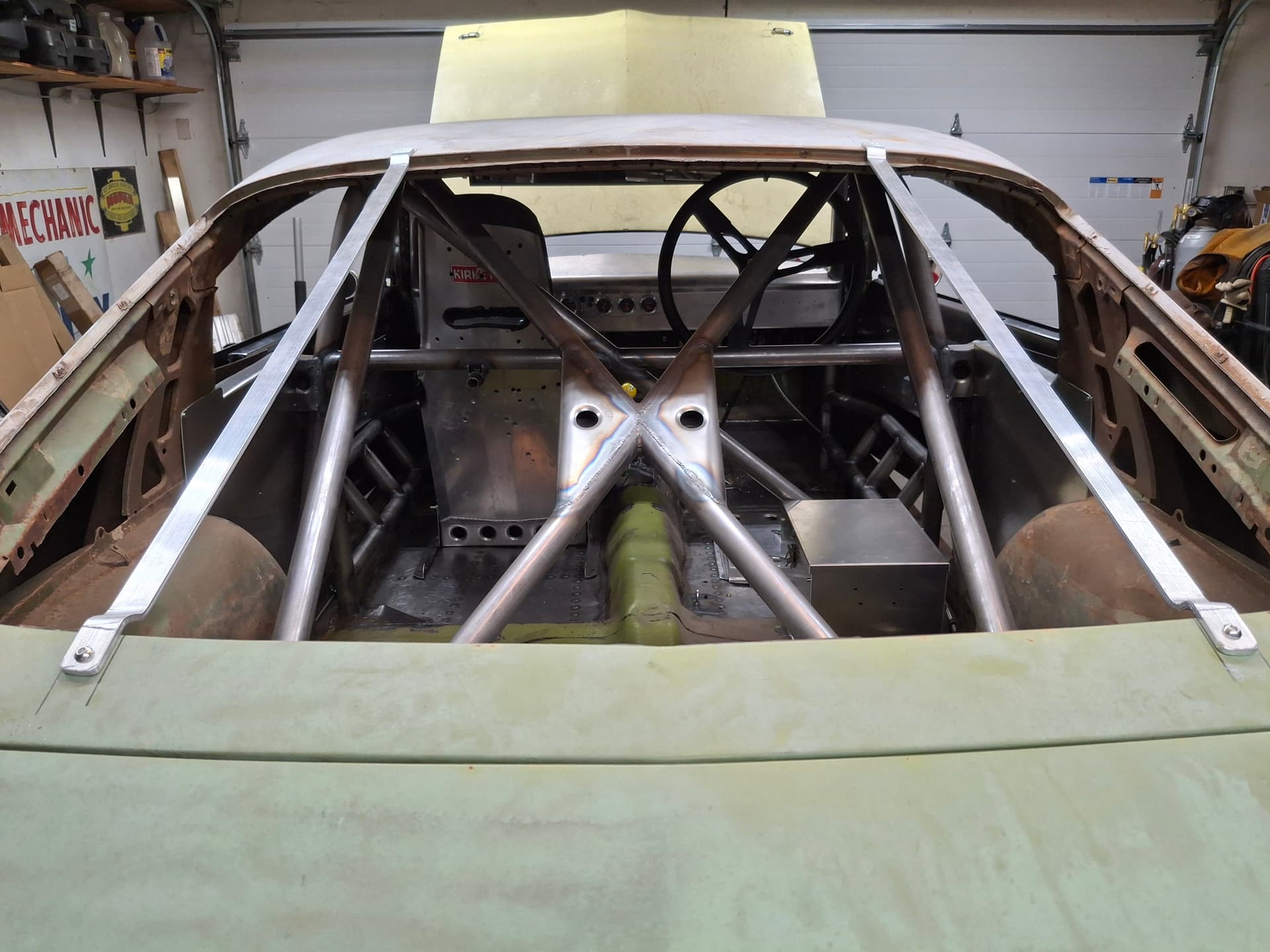
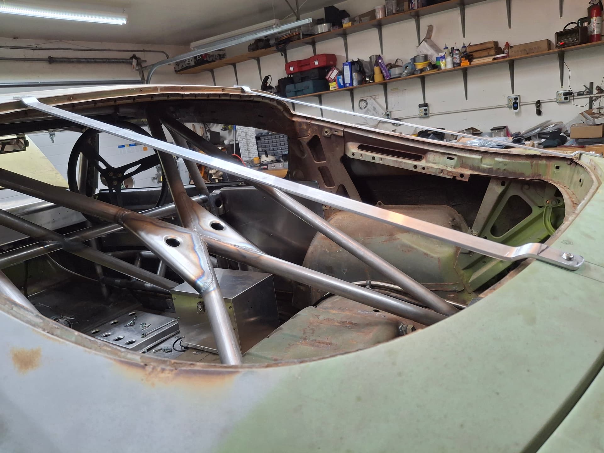
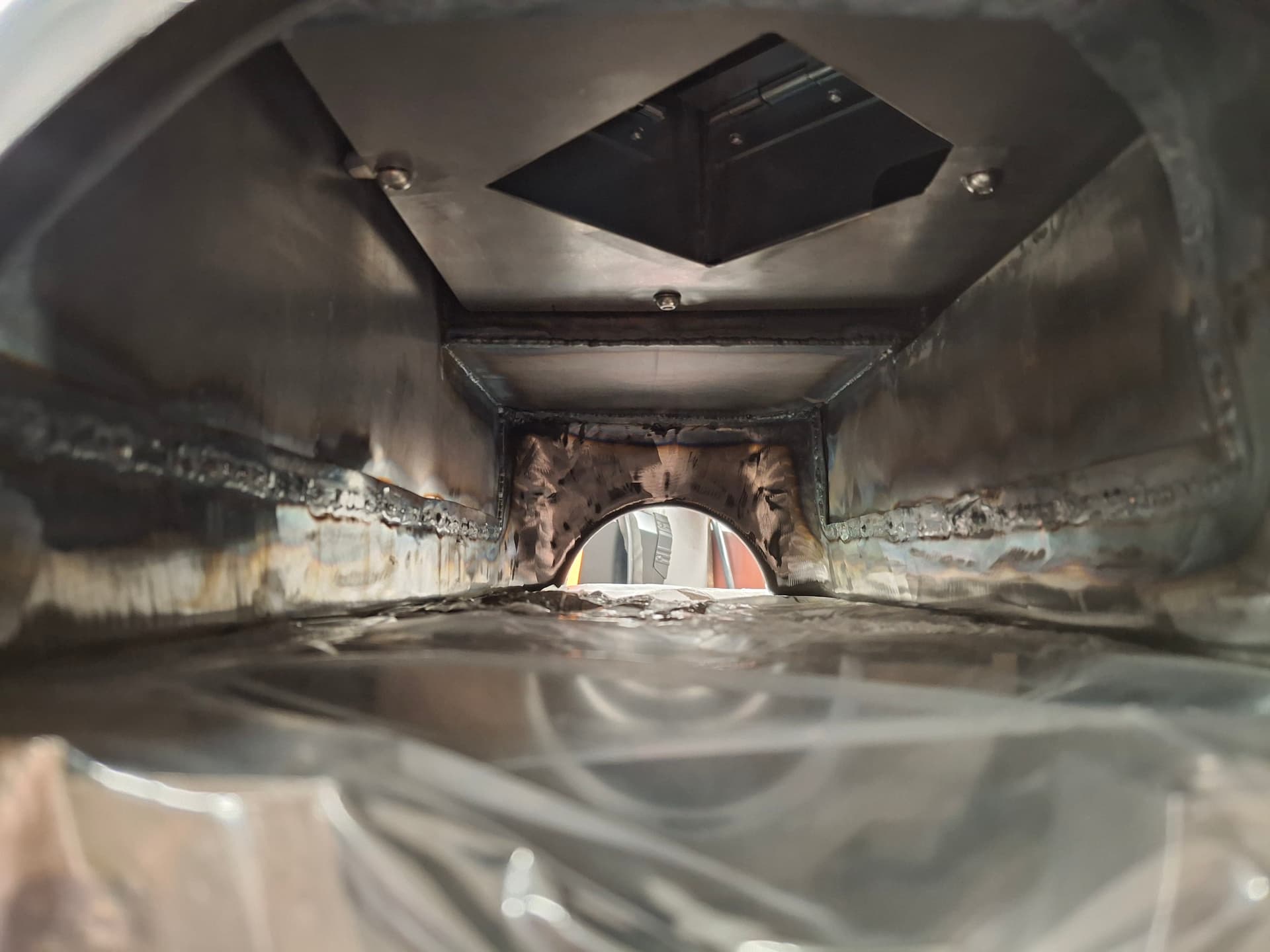
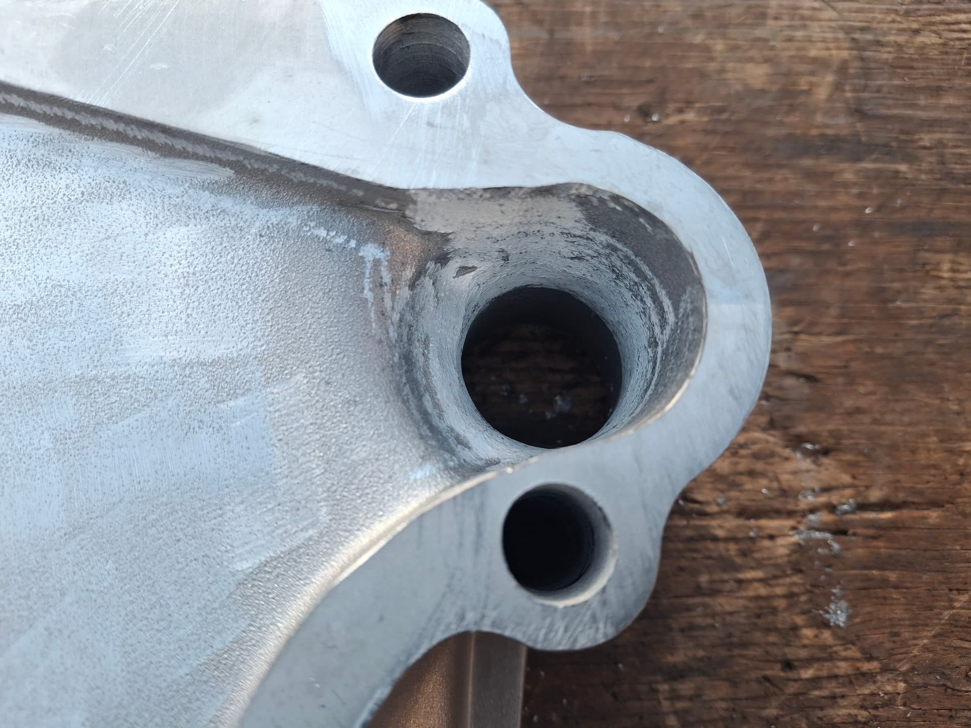
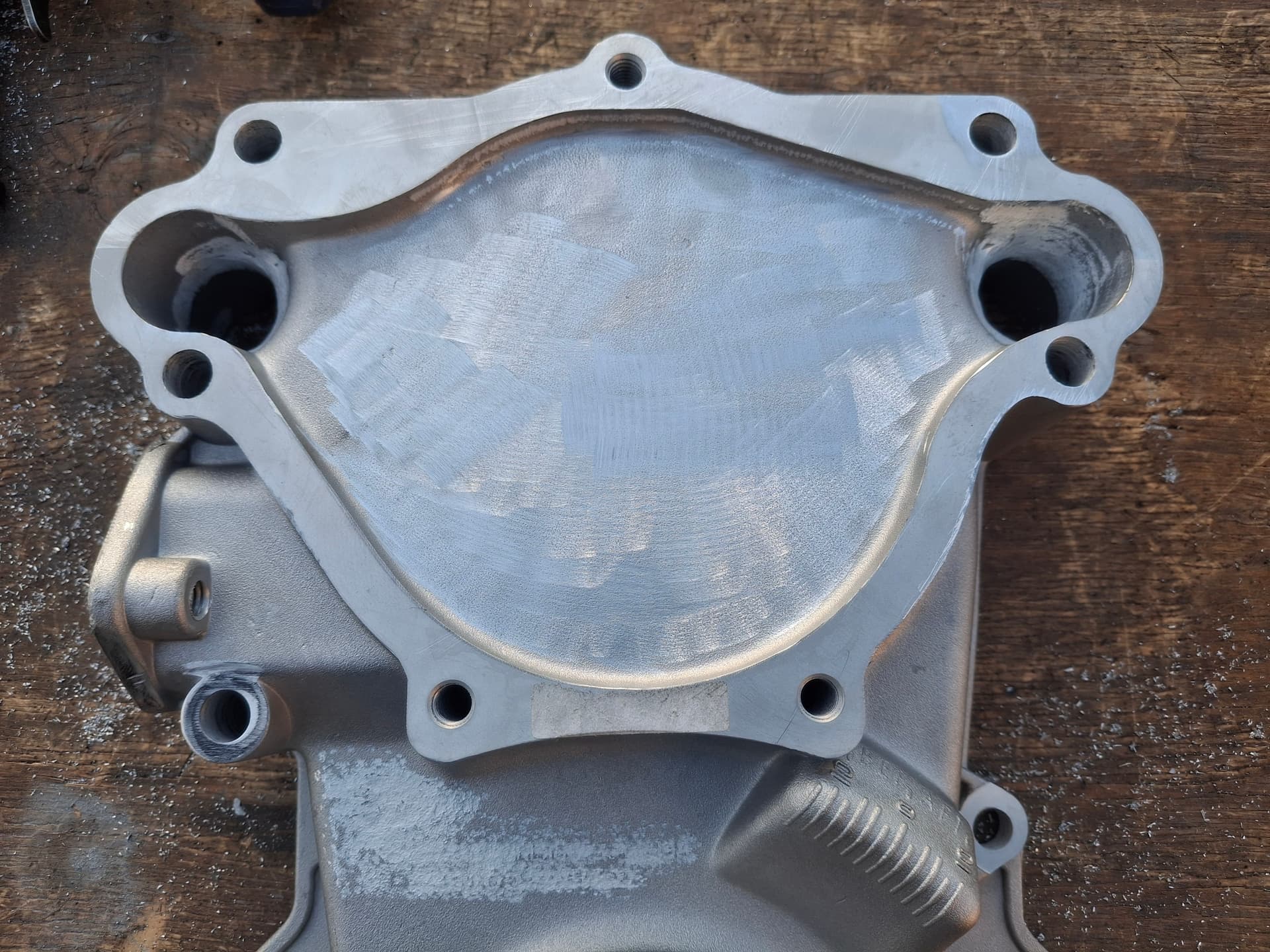
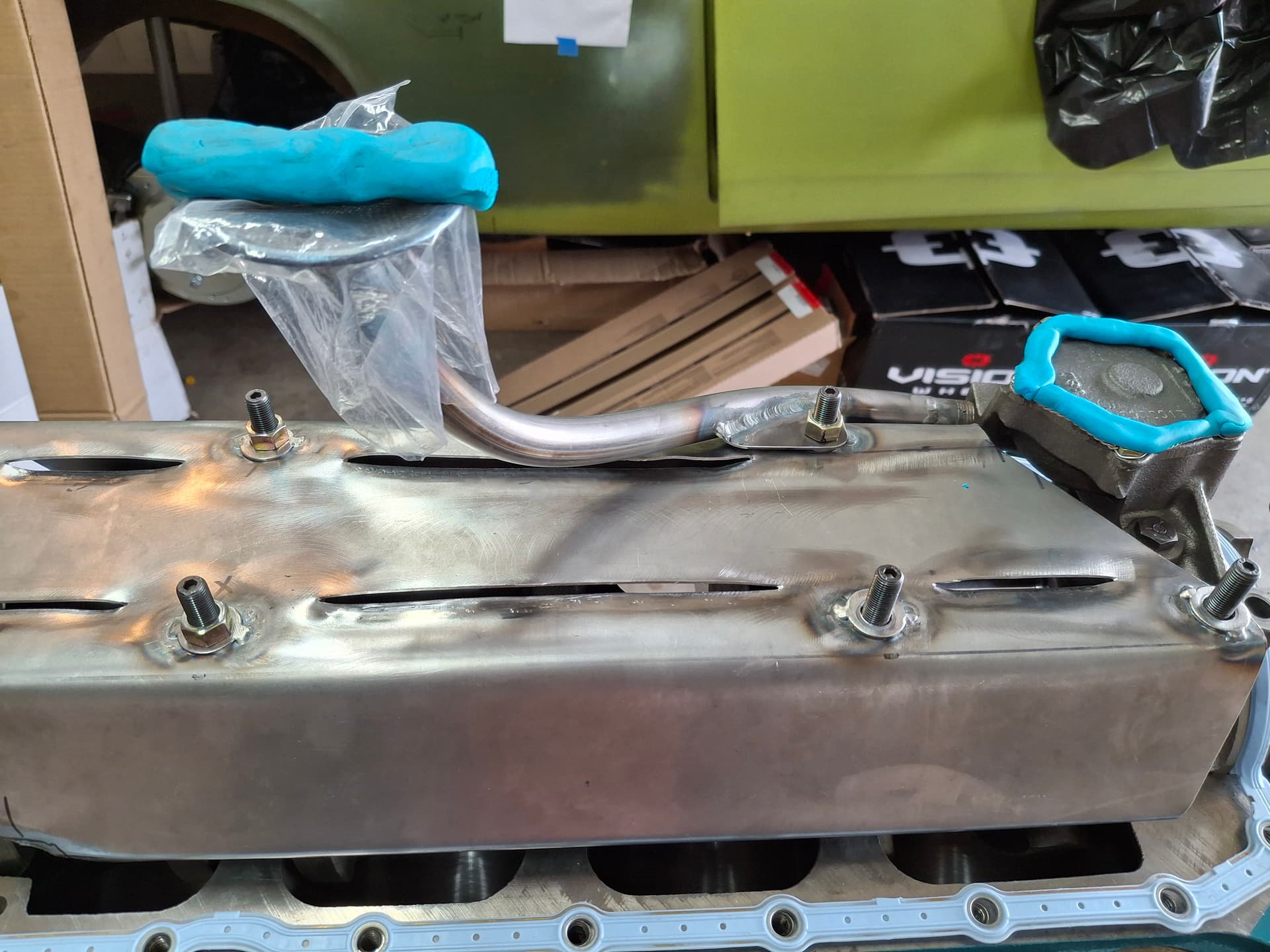
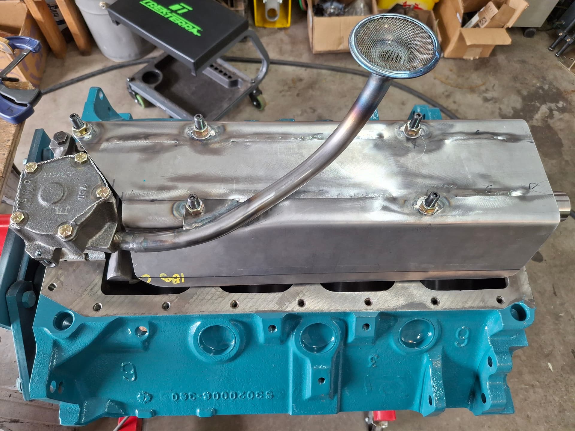
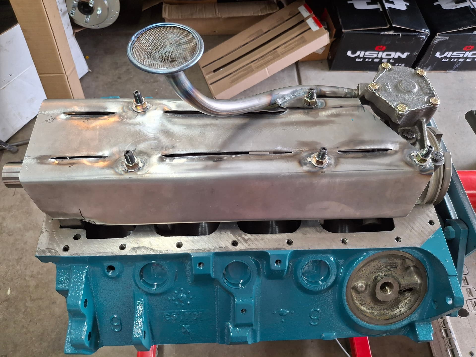
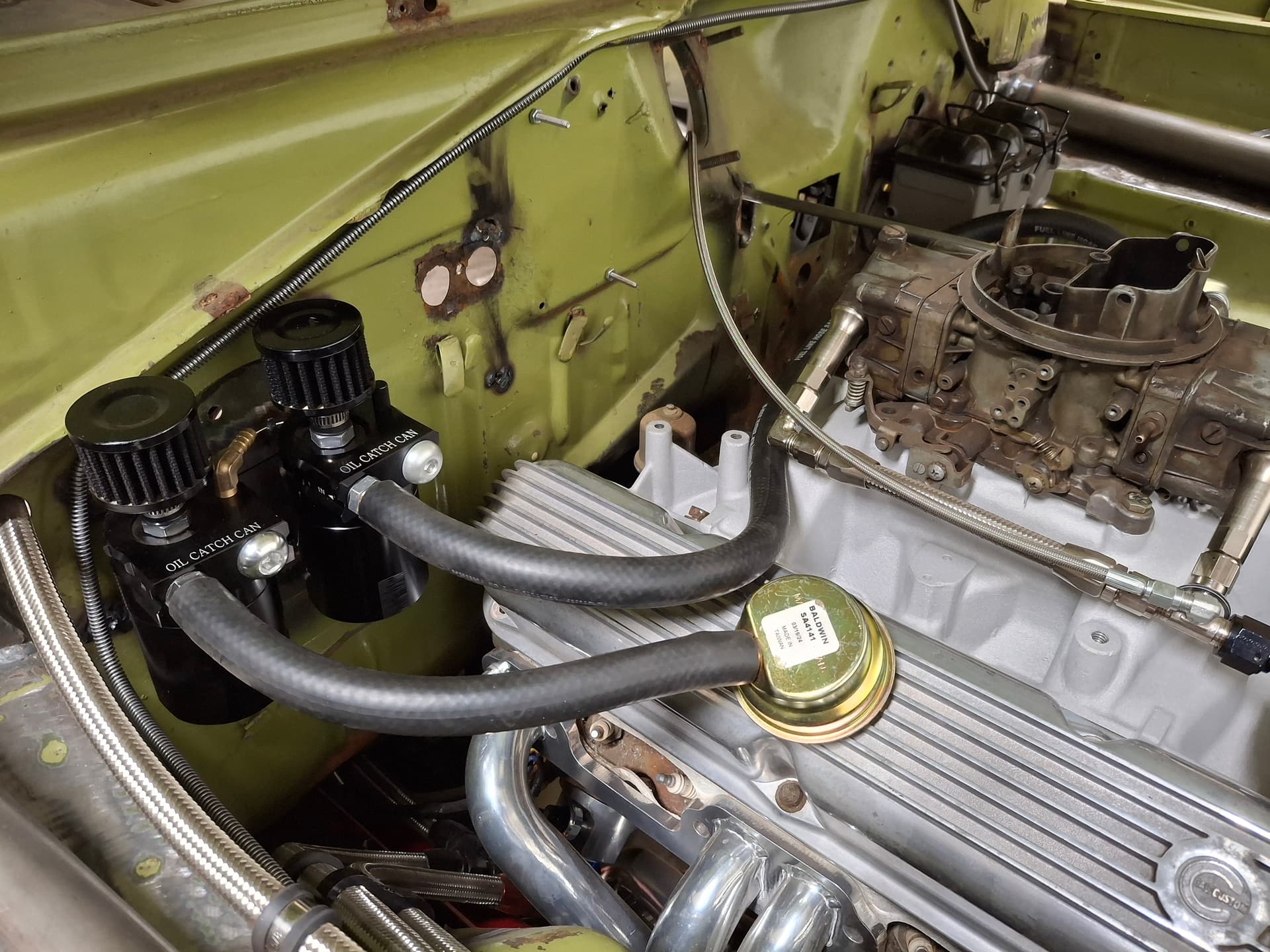
I welded up the factory heater blower-motor hole in the firewall since I’d need that space for mounting the oil catch tanks. To help the crankcase breathe and to meet RMVR’s General Rule on catch tanks, I modified and installed two aluminum catch tanks (to meet the volume requirement and provide ample breather volume) to which each valve cover connects using 5/8" hydraulic hose. I used a burr bit to modify a 1990’s Mercury grommet that was wide enough to fit the valve cover cap hole so it would accept the 1960’s style Mopar breather. The catch tanks feature an internal stainless-steel mesh filter and baffle system that condense and drop out hot oil vapors entering the tank before the air is vented to atmosphere through the cotton-gauze breather. The tanks spin off from the bottom for emptying/cleaning.

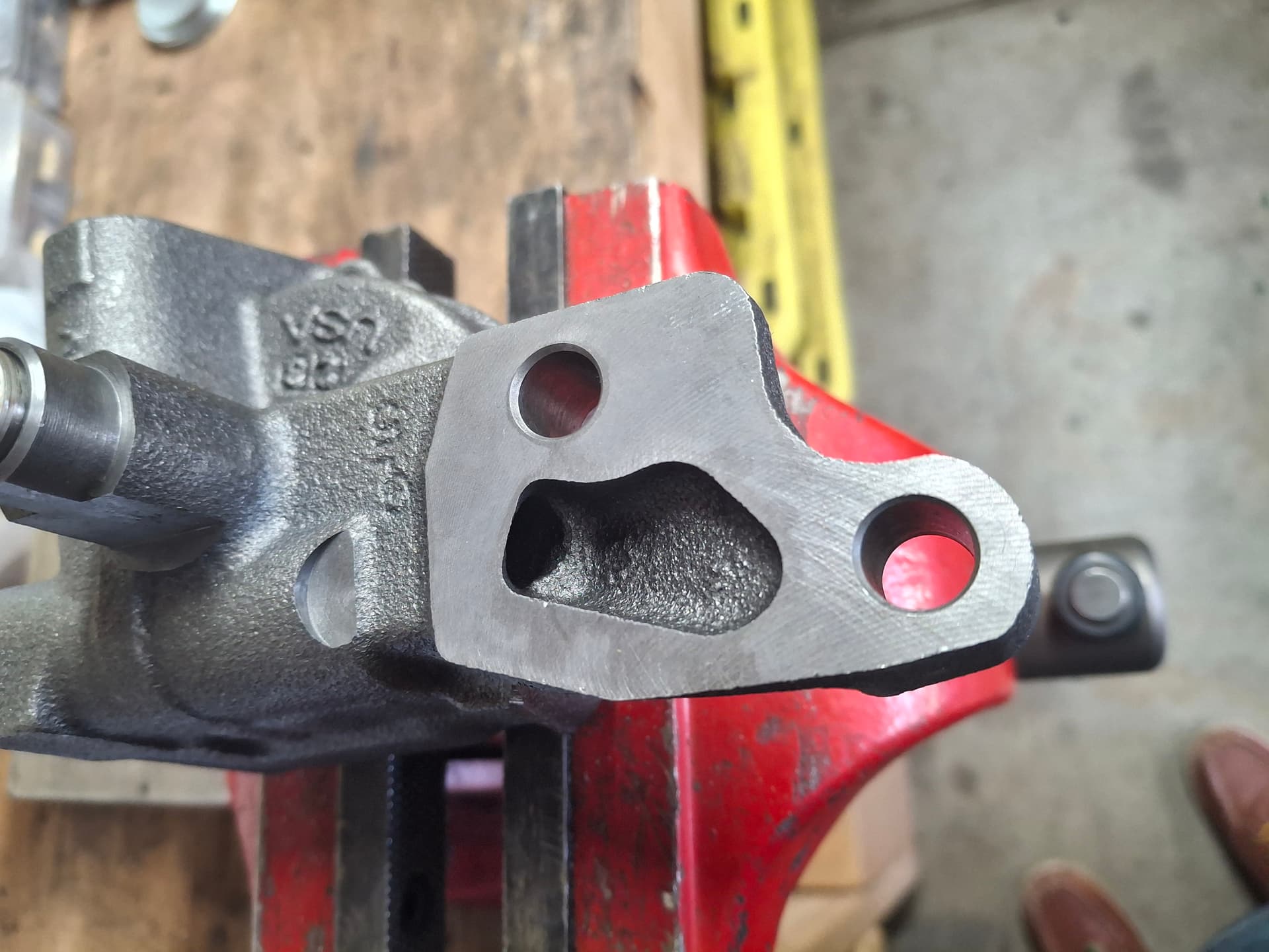
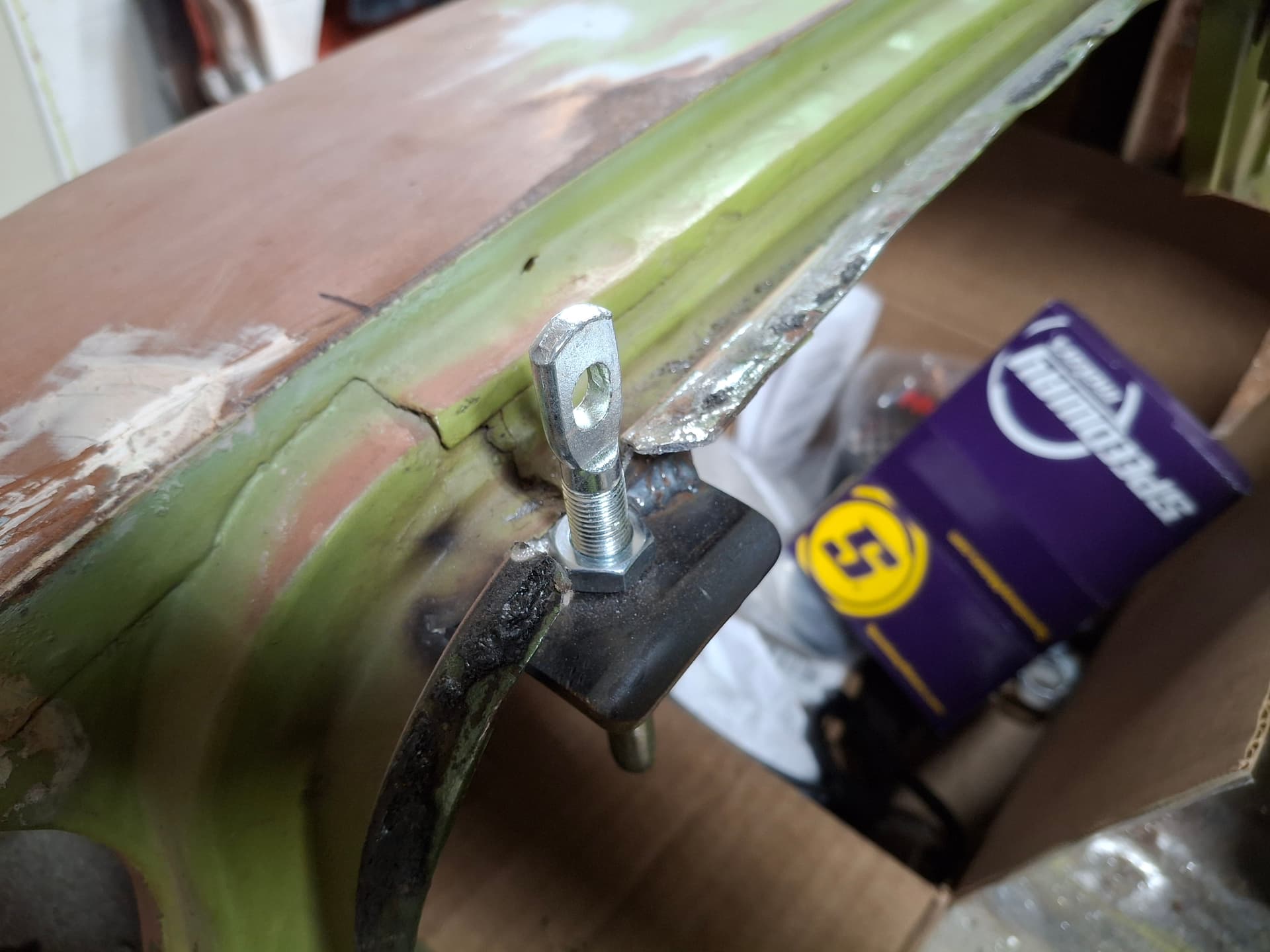
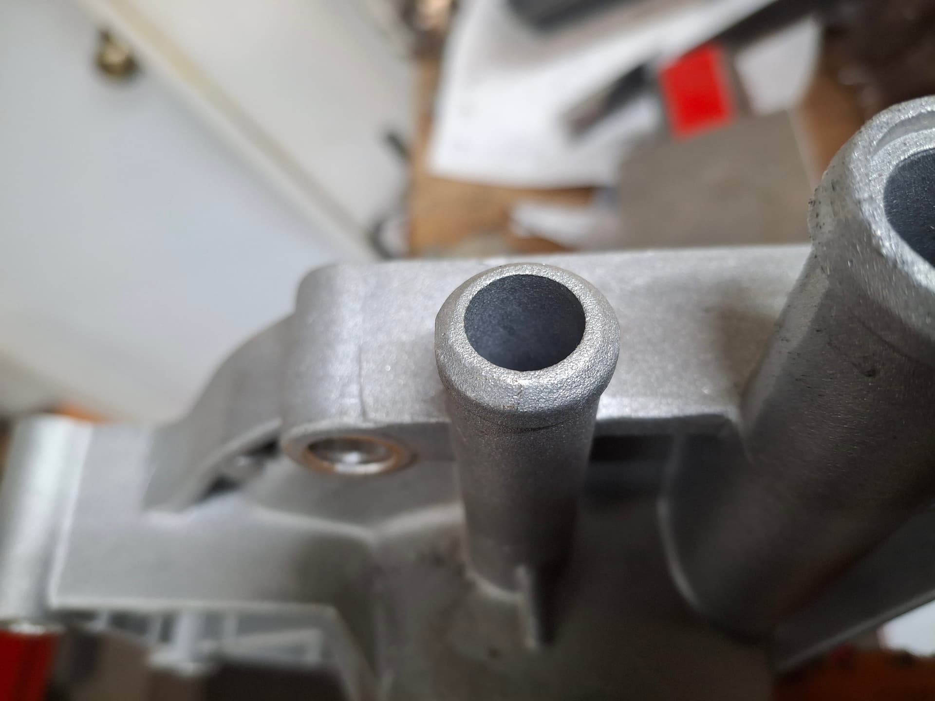
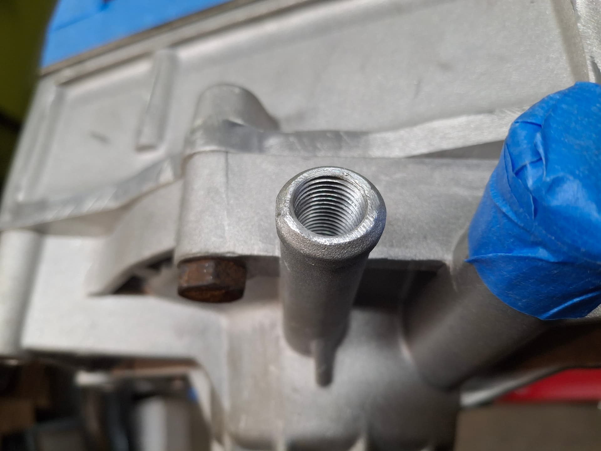
For the right catch tank, I drilled and tapped a new port to 1/8" NPT and installed a barbed elbow. I drilled and tapped an 1/8" NPT port into the transmission tail housing (not pictured yet), and the vent hose will run from the transmission port to this new port in the catch tank to vent the transmission as well.
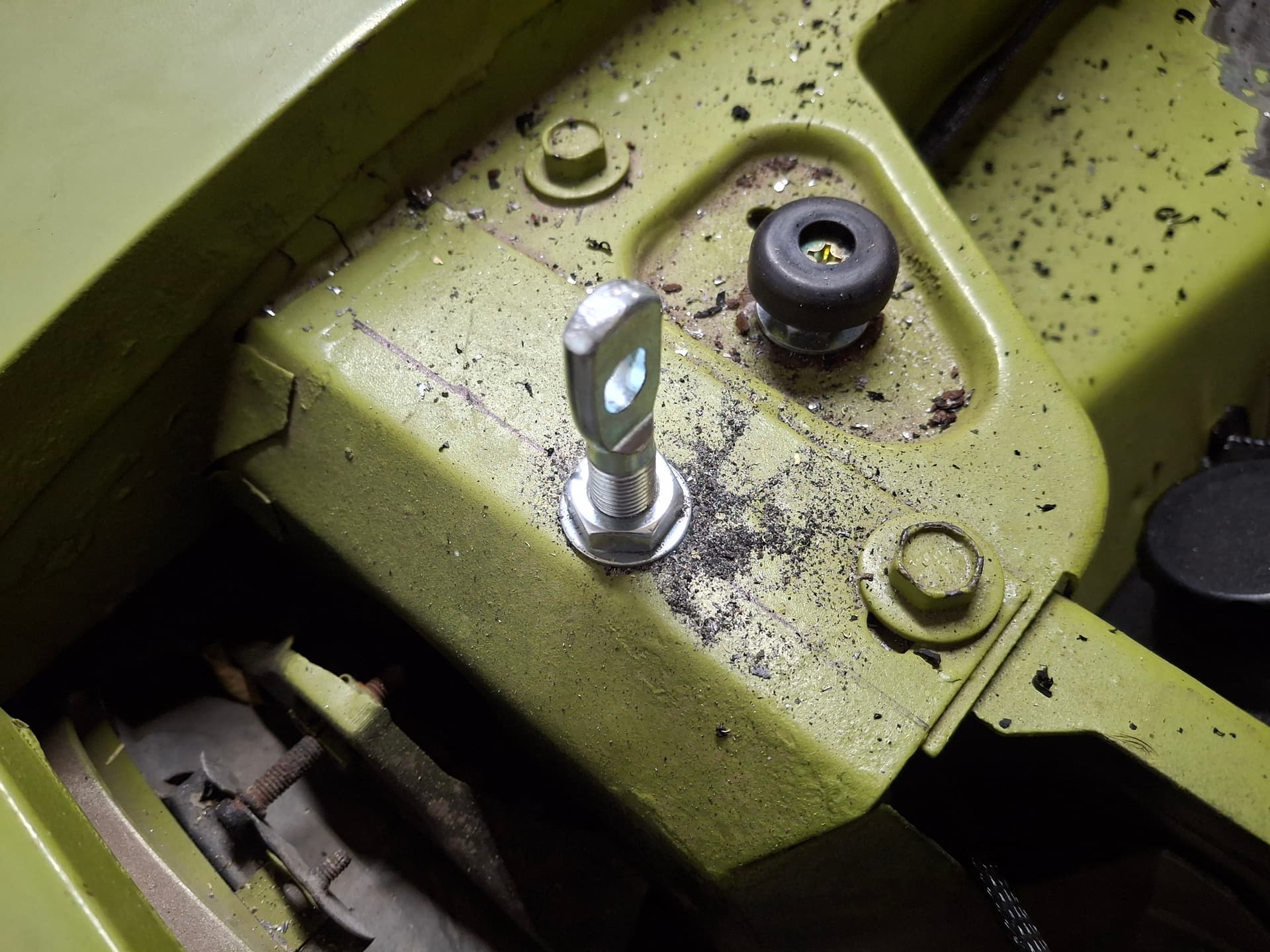
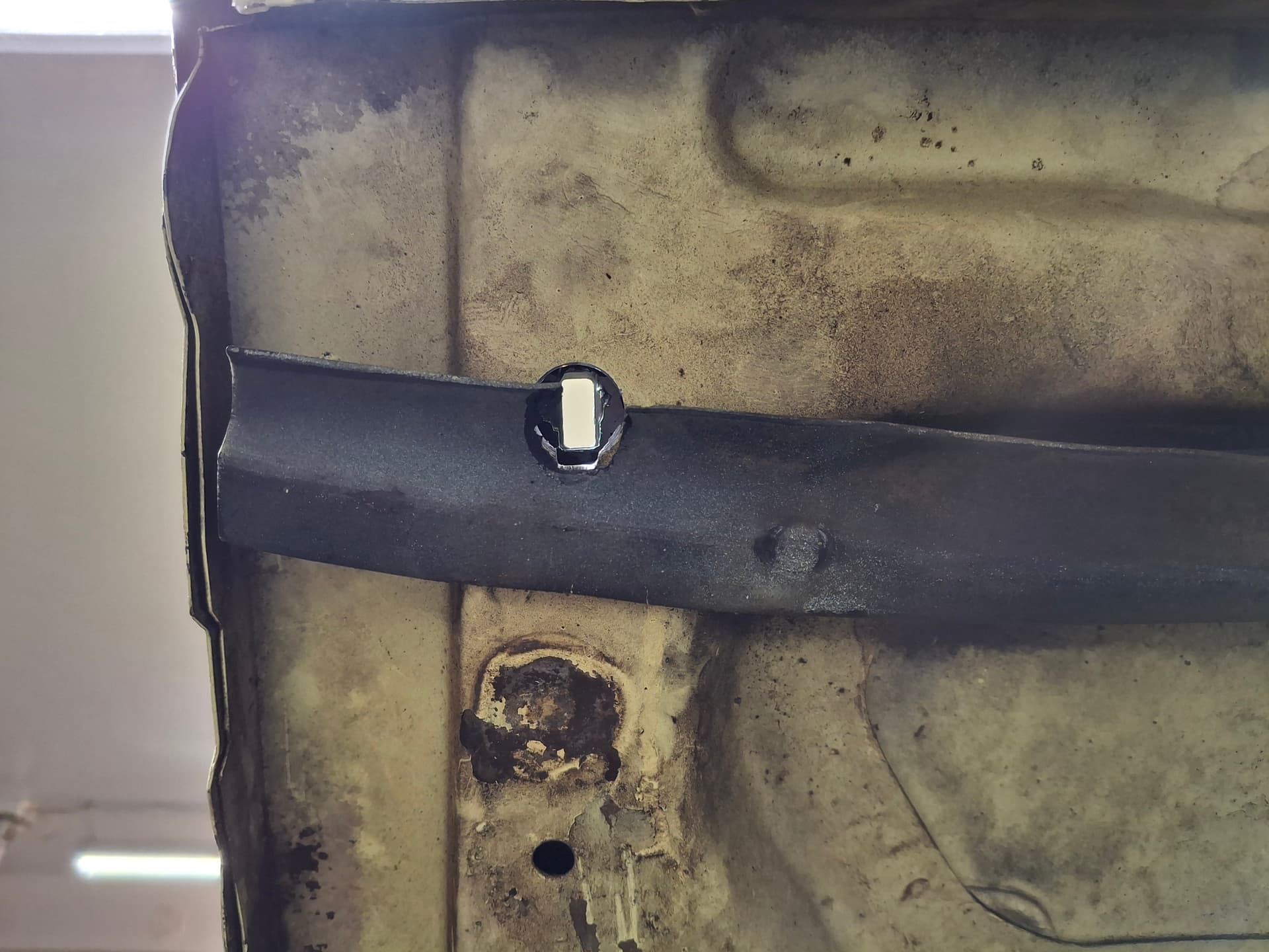
Shifter Boot
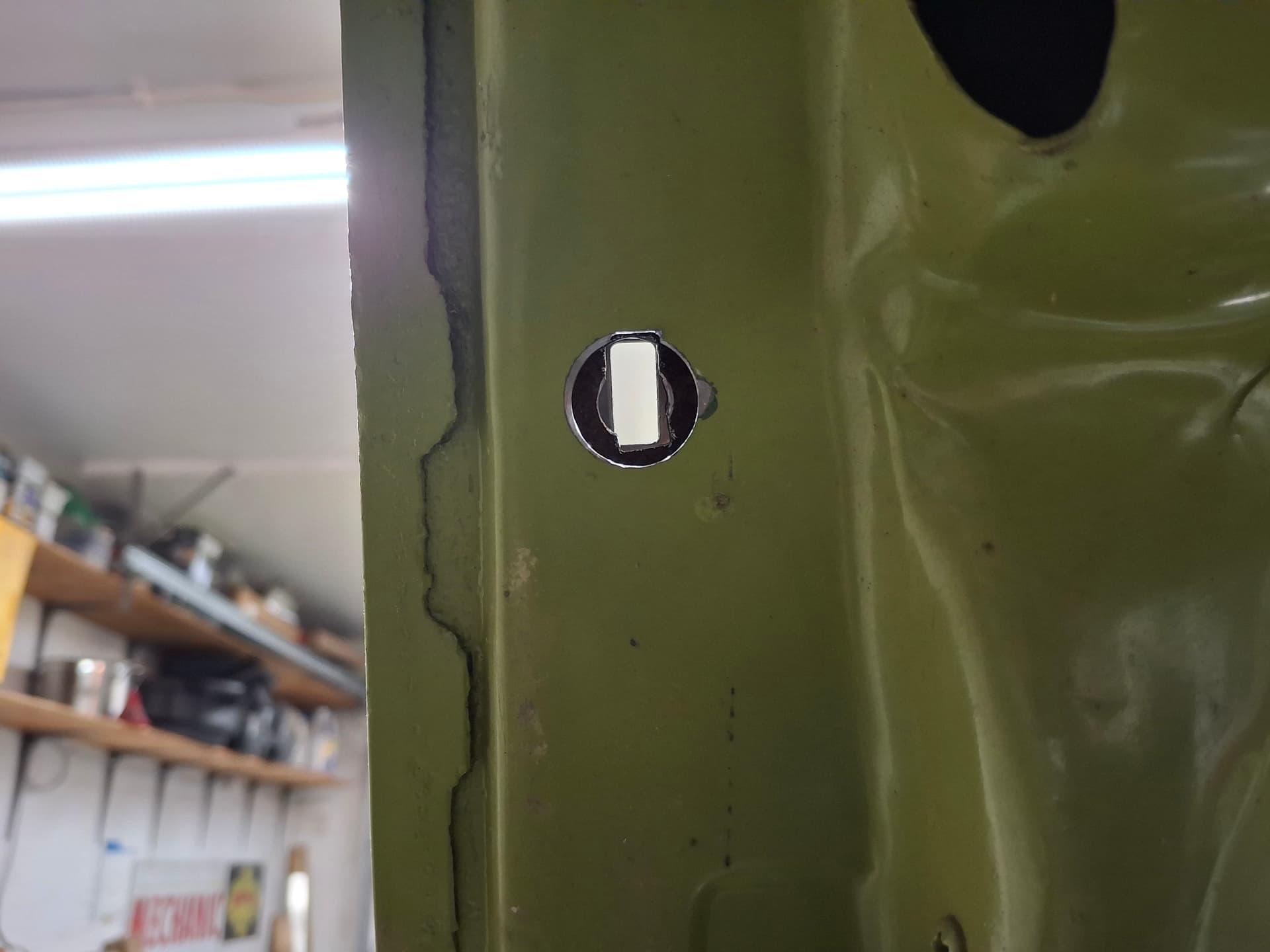
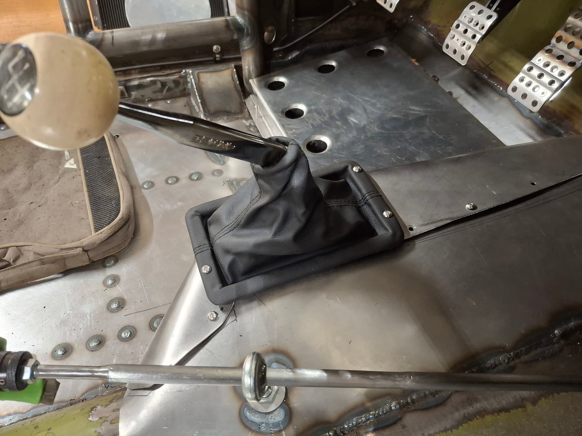
After some internet digging, I found a shifter boot that both fits over the Competition Plus shifter and works, for the most part, with the oddly shaped transmission tunnel cover. I think it is originally for a Toyota or Honda. The one corner protrudes a bit, but that can’t be helped due to the shifter body. I drilled holes through it and the tunnel cover and attached it with #10 machine screws and nylock nuts.

Dashboard Emblem
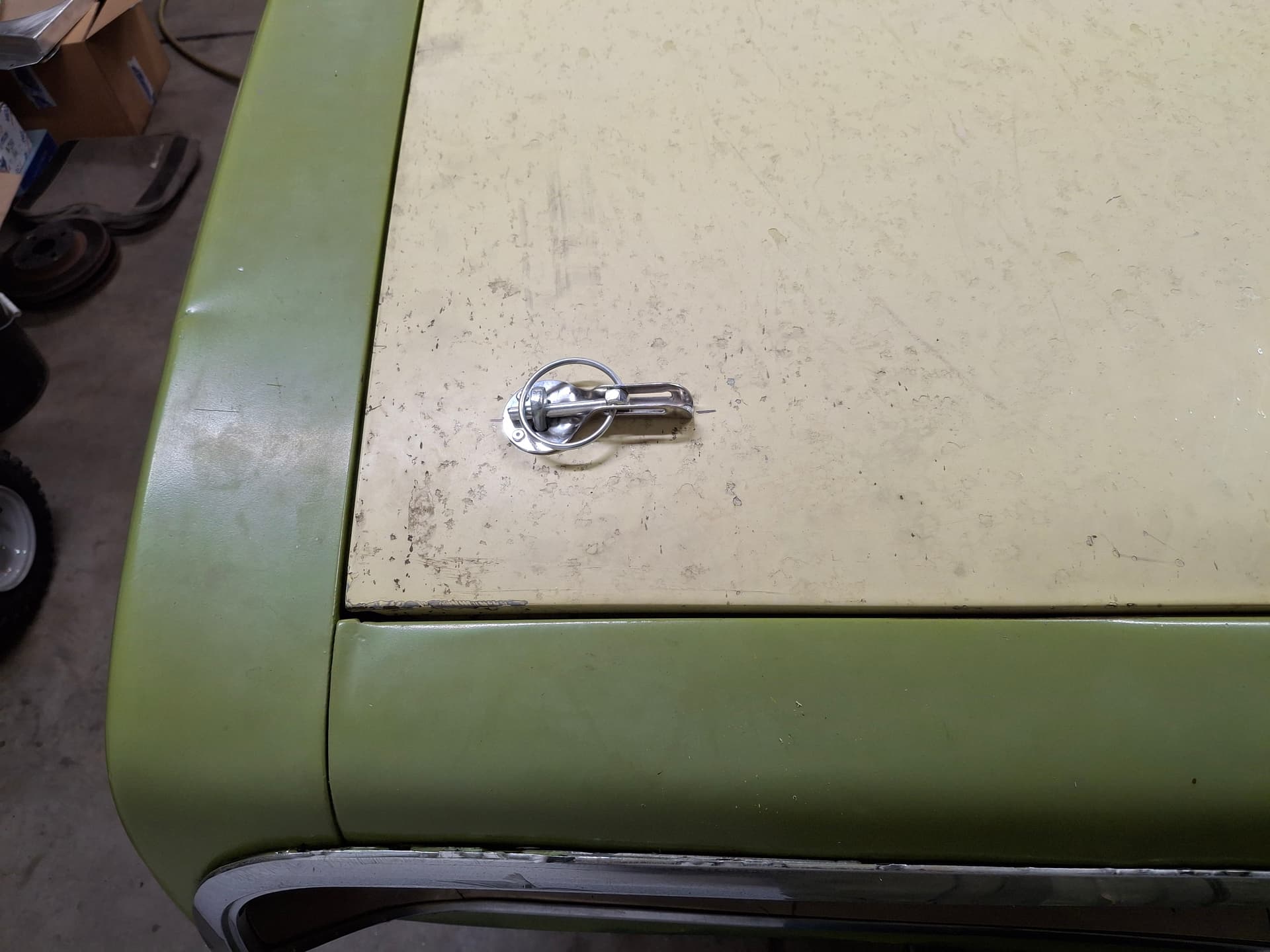
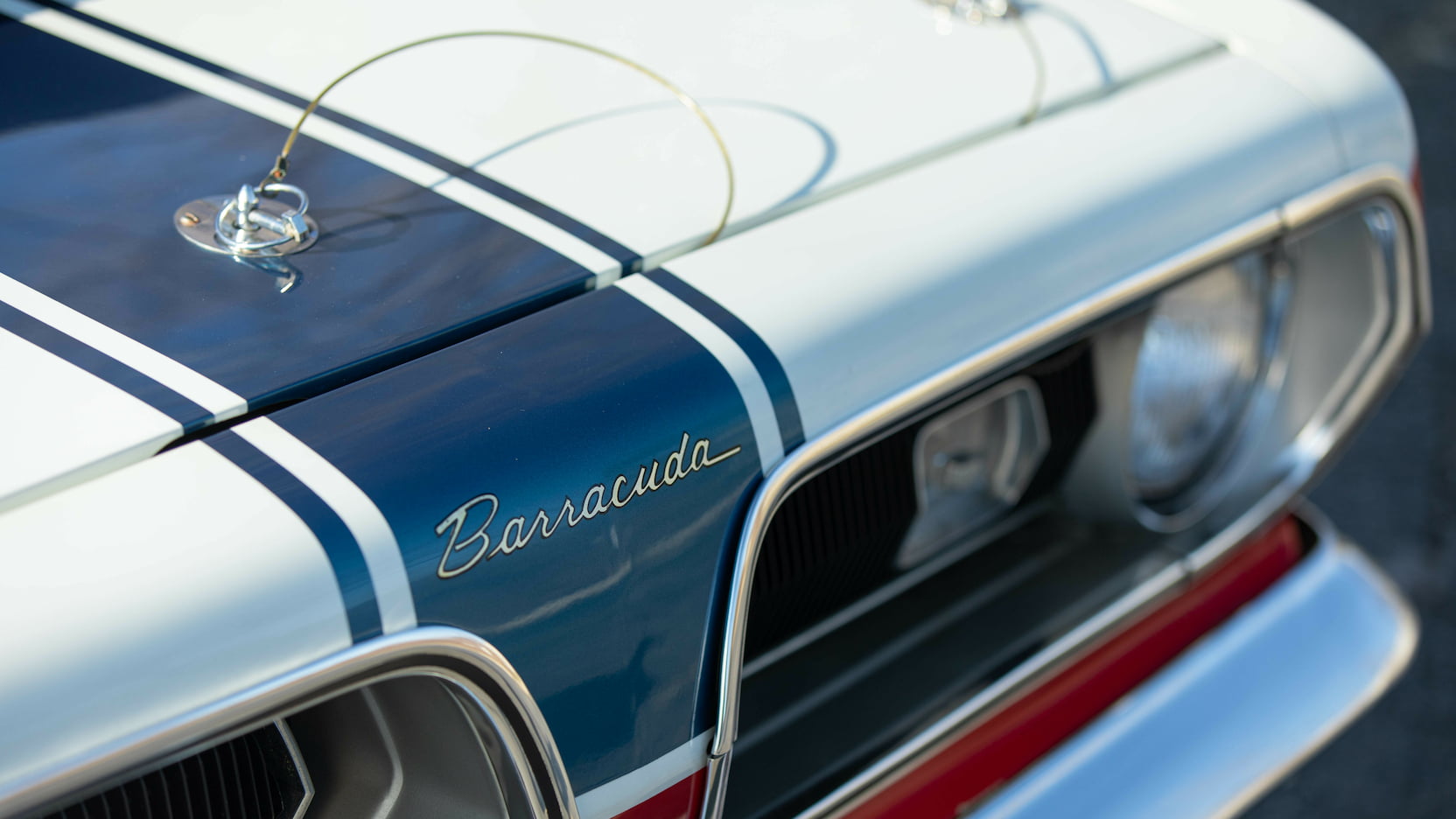
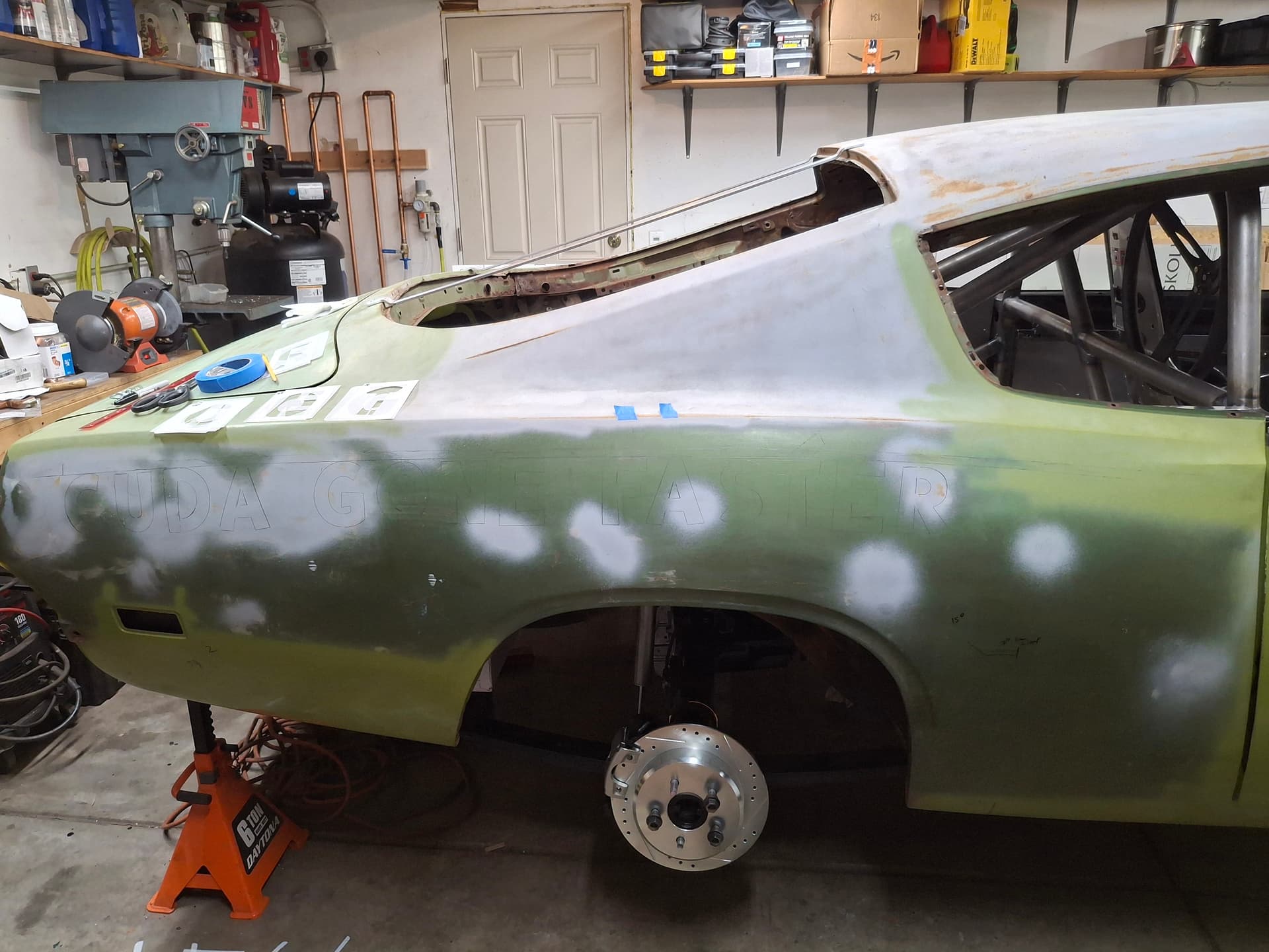
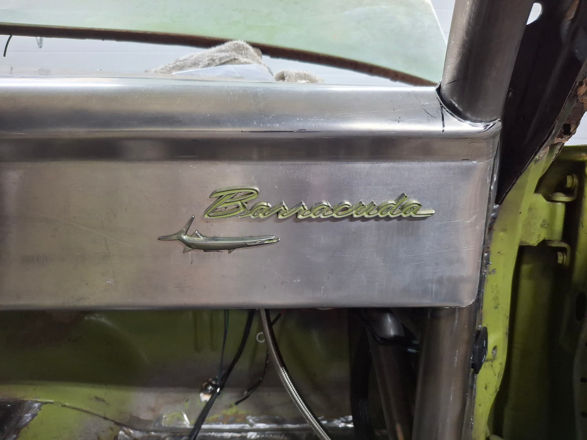
You know I’m progressing in the project when I start considering inconsequential aesthetics :joy: I removed the only remaining emblems on the right fender and repurposed them onto the dashboard to let curious lookie loos know what fish they’re messing with :joy:. Eventually, the emblem’s green overspray will get painted something different (black was factory, but maybe the white of the car against the black dash?).

Post Alert Pings:
@jonUU
@Sportsracer
@Datsun78
@Bob_Alder
@Rich
@Nick_H

1 Like

"So many variables, but I’ve decided to go with the LD340 . . . for now. "

You’re such a Cuda nerd!

Justin
Looking good buddy, love the fender emblem on the dash!
That intake manifold style was very popular in the 70’s, my 1970 Boss 302 had a very similar setup. That’s is until I installed a Tecalemit/ Jackson constant pressure fuel injection on it. The carb was a much better set up for the street.

Tom

@Bob_Alder, that’s the nicest thing you’ve ever said to me :joy:

Happy New Year to both you and Tom @Sportsracer.

Engine Disassembly and Oiling Modifications

I neglected to post this work I did back in October, so here ya go. I brought the engine out of mothballs where it’s been for about seven years since I pulled it from a truck in a pick-a-part. The only thing I’m using from it is the block, so everything else went into either the sell or scrap pile. I removed all the oil gallery plugs, cooling expansion plugs, camshaft bearings, and distributor/oil pump driveshaft bushing.

Before I delivered it for machining, I did some work on the oiling system. All the sharp turns in the oil galleries I could reach with my long burr bits got eased.

I removed all the casting flash from the lifter valley to increase the speed of oil drain-back and to remove stress risers (I also removed casting flash from outside the block to remove stress risers too). I ground the two main front drain-back holes down as far as I could and ramped them to where oil doesn’t have to pool as high in the lifter valley before draining into the timing cover down into the pan.

I smoothed the oil-filter well and rounded the sharp turn down in the oil-filter exhaust port where the filtered oil enters the main oil gallery.

I scribed a new oil-pump gasket onto the rear main cap and ported the cap to match the gasket and to smooth the overall shape.

The small-block Mopar’s crankshaft thrust journal (on bearing #3) isn’t direct oiled but relies on oil seeping out of the main bearing. With a manual transmission with high-pressure clutches, the lack of direct oiling on the rear thrust journal can become an issue and lead to wiping out the journal and/or bearing due to friction. To address the issue, I installed the new main bearings and cap on #3 and drilled a 3/64" hole through the rear of the bearing and through the block web into the main bearing’s oil gallery. I beveled the hole to remove the raised edge. Now, the rear thrust bearing receives constant direct oiling.

After I finished all my machining, I sprayed the engine with my go-to degreaser for such things: Walmart brand oven cleaner of all things. I mixed up a highly concentrated gallon of hot water and my second-favorite degreaser: original Pine Sol of all things. Believe it or not, both of these cleaners eat heavy grease better than anything else I’ve tried. Using long engine riffle brushes, I scrubbed out all the oil galleries with the Pine Sol solution. I ran thread chasers through all the threaded bosses/ports. I used rat-tail files to clean out all the cylinder head coolant ports in the deck. I used a razor blade and 120-grit sand paper to clean up the coolant expansion plug bores. I took scrub brushes and attacked both the inside and outside of the block. After I scrubbed everything well, I hit the block, coolant passages, and oil galleries with a pressure washer until they were clean. Lastly, I dried everything with compressed air and spent a lot of time blowing out the coolant passages of any remaining chunks. Even though the machinist will do a thorough cleaning, I always like to do this pre-machining cleaning to help ensure the block is as clean as possible. Call my crazy, but I actually scrub the oil galleries, cylinder walls, and block again with Dawn dish soap after I get it back from the machinist before assembling so that I know for a fact it is clean.

I drove up to Fort Collins and handed off the block, new forged crankshaft, new forged connecting rods, new forged pistons, new piston rings, and new main and head studs to our very own Pete Christensen back in late October. Pete is going to clean the block (bake and shot I believe) punch out the cylinders 0.030" along with a torque-plate hone, check line bore with the new main studs and line bore if necessary, and balance the rotating assembly. Once he has the block bored, I’m going to install the crank and corner pistons to measure deck height, and Pete will then deck the block to zero-deck depending on those measurements. Once all the machine work is completed, I’ll bring everything back to my house and assemble the engine.

Post Alert Pings:
@jonUU
@Sportsracer
@Datsun78
@Bob_Alder
@Rich
@Nick_H

1 Like

Oil Pump Porting and Blueprinting
After four months on backorder, my Melling M72 high-volume oil pump arrived. I disassembled it and blueprinted all the parts, confirming tolerances were within spec and making adjustments as needed. I used burr bits and stones to port the intake, chambers, exhaust, and cover to remove all the rough casting and machining and to smooth everything. I gasket-matched the exhaust flange that bolts to the rear main cap, which I also gasket-matched previously. After I cleaned everything, I filed down a 1/16" thick washer to use as a spacer in the pressure-relief spring to bump the oil pressure slightly, which should be a bump of about 5 psi above 1,500 RPM from my experience. Rather than using the factory bolts with their thin heads, I drilled 1/16" holes in grade 8 bolts, applied red thread locker, torqued down the cover, and installed 0.032" safety wire as a precaution; it’s likely unnecessary, but it can’t hurt.

Air Cleaner and Carburetor Spacer
To see how much carburetor spacer I can get away with for hood clearance, I installed a 1" phenolic spacer. I fitted an aluminum dropped air cleaner base, a Speedway Motors 14" x 3" washable cotton-gauze filter, and an aluminum powder coated dropped air cleaner lid. I used a long aluminum nut due to the recess in the lid, and I drilled a safety hole through the 1/4" stud and fitted a hitch pin for good measure in case the nut backs off. I applied four balls of Play-Doh to the air cleaner that told me I have a comfortable 3/4" of hood clearance at the tightest spot, which is fine with solid motor mounts.

Hood and Deck Lid Latches
I decided to ditch the deck lid center latch and key and go with pins. All the factory latch hardware went in the “sell” pile. I welded tabs onto the interior opening and cut out the weatherstrip ledge to make room for the nuts. After laying out the holes on the exterior, I drilled and tapped the tabs to the pin’s 7/16"-20. Hand filing contoured the openings in the deck lid, and I pop-riveted on the latch plates. I drilled through the bottom of the deck-lid opening and installed 5/16" adjustable rubber stoppers where I dialed in the closing height in conjunction with the latch pins for a snug fit without rattling. I repeated this process on the hood only drilling through the core support to locate the pins. The only part of the factory latch system I retained on the hood was the spring that pops up the hood about 1" once I release the pins to where I can get my hands under it to lift it. I’m retaining the factory hood hinges and springs since I don’t want to have to fool with a prop rod and the springs are a lighter coil-type.

Rear Window Straps
Spec requires at least two 1" x 1/8" rear window straps. With such a large window with the possibility of wind deflection, I bumped up to 1" x 3/16" aluminum strap. I experimented with placement for the best view from the driver’s seat. I annealed the aluminum with a torch and bent “Z"s in the straps so that they will rest flat against what will soon be the polycarbonate rear window. The straps are secured to the body with 1/4” bolts and nylock nuts. Eventually, they’ll get painted, likely either the off-white of the car or the gray of the interior.

Post Alert Pings:
@jonUU
@Sportsracer
@Datsun78
@Bob_Alder
@Rich
@Nick_H

1 Like

Distributor and Spark Plug Wires
I mocked up the MSD Pro-Billet distributor and built the spark plug wires. I went with low-resistance 25 ohms per foot FAST 8.5 mm wires. Eventually, the wires closest to the headers will get heat-protective sheathing. I drilled a new hole in the firewall and ran the coil wire from the distributor down to the coil.

Roll Cage Padding
I installed high-density cage padding on the driver and passenger front hoop sides and across the roof diagonal.

Post Alert Pings:
@jonUU
@Sportsracer
@Datsun78
@Bob_Alder
@Rich
@Nick_H

Experimenting with the Livery
To give you an idea of where I’m headed, my vintage race car paint aesthetic is heavily influenced by WWII aviation nose art, 1940’s - 1960’s Champ/Indy cars, and 1960’s drag cars. My grandfather on my mother’s side was a B17 ground-crew chief for Douglas Aircraft stationed in India during the war, and he helped build and served as a mechanic on a 1948 Indy 500 car, “The City of Tacoma” that placed sixth. While my grandfather passed shortly before I was born, my childhood memories include looking through old Indy 500 programs and WWII aviation books and watching films. My mother and father were 1960’s hot rodders and drag raced at their local strip in Southern California, so I was surrounded by drag racing as a child and young adult. In particular, I was drawn to 1960’s Factory Lightweight and Factory Experimental altered-wheelbase cars and the beautiful paint jobs with fun names like “Chevy II Much,” “Rambuncious,” “Scootin’ Cuda,” “Hemi under Glass,” “Star Dust,” “Melrose Missile,” “California Flash,” “Daddy Warbucks,” “Mr. 5 and 50,” “Seaton’s Shaker,” “Blairs Speed Shop,” Landy’s Dodge," and many others.

So here I am planning the livery for the Barracuda, and I can’t help but feel my roots. My current plan is to paint the exterior off-white “International Harvester White” by way of Tractor Supply. The car will have a racing stripe design borrowed from the “Sox and Martin” Barracuda, and I’m 90% set on burgundy-ish “International Harvester Red” for the stripes, again, by way of Tractor Supply, although 10% of me is still kicking around dark green. The interior will likely be primarily light gray with black dashboard and upper door panel accents.

Now for the lettering/numbering. I really want to use engine-turned gold leaf with black outlined striping. The rub is that I’ve never done gilding let alone engine-turned the leaf after applying it, nor have I outlined letters or lettered by hand brush. You’ll be learning along with me. I’ve purchased the necessary gilding, engine-turning, and striping tools/materials, watched/read as many youtube videos/articles as I can find, and spoken to the gilding size manufacturer for tips (“size” is the leaf adhesive if you’re curious). I’m confident I’ll get the hang of it good enough for my own race car. What better way to learn and experiment with the livery than to start on the current paint that will eventually get blasted off anyway when I do the final livery? I dug through hundreds of letter stencils available online and found one that looks like a font similar to those used on 1960s cars that has a little more character to it than block letters.

For the numbers, I was extremely, pleasantly surprised when the most recent numbers purge of unused cars freed up my childhood hero’s number: #14 used by Bill Vukovich. The number was also used by A.J. Foyt, so that’s cool too. I am not one to have heroes, but I always admired Vuky since he was also a California boy who started with very little and worked with what he had to make his life better. I’d be proud to be the RMVR caretaker of his number. I found photos of Vuky’s 1954 Indy car (he won that year), figured out the scale via ruler, and hand-drew the larger number onto sheets of mylar for a stencil. The number body will receive engine-turned gold leaf and a brushed black outline–at least that’s what I hope my hands and brain can do.

I just can’t leave the car unnamed after I put so much spirit into building it from the ground up. I’ve spent a year playing with a dozen different names and have chosen “Cuda Gone Faster.” Either the Barracuda will have gone faster than others on track, or if I stink on track, the Barracuda could have gone faster if someone else were driving it. :joy: It’s the ultimate hedge. I also think it will give the children at RAKC a smile, so why not? These letters will get engine-turned gold leaf and black outlining like the numbers. If you’re curious, the other top names I came up with include “Shifty Fish,” “Hook and Cook,” “Bait and Shift,” “Something Fishy,” and “Cuda Been a Hemi.” I still really like Shifty Fish, though, and it would certainly be easier to letter. Which one do you prefer, out of my curiosity, and none isn’t an option?

I placed the '81 GT-1 class at the bottom of the quarter panel, and these will likely get brushed black.

I placed my name and responsibilities atop the door so I don’t forget them, and these will get brushed black.

Sox and Martin racing stripes I intend on borrowing:


Bill Vukovich’s 1954 car number I duplicated:


Laying out the door numbers:


Laying out my name atop the door:

Laying out the class identifier:


Laying out the car name:


Post Alert Pings:
@jonUU
@Sportsracer
@Datsun78
@Bob_Alder
@Rich
@Nick_H

1 Like

Justin
Nice bio and family racing history, really enjoyed it! I’m happy to see your attempting your own lettering and graphics. I too dabble with doing my own paint, sometimes it comes out great and I feel like wow I’ve learned a new skill! Then the next time it looks like a 4 year old’s rattle can experiment😩

As far as your name ideas I think your choice is amazing. For me though I like “Cuda been a hemi”.

Keep having fun!
Best
Tom

Great post. Keep 'em coming.

It’s hard to keep the garage somewhat comfortably warm in this cold, but I’ve been picking at things like replacing standard nuts with nyloc nuts, installing star washers where applicable, etc. My next focus is to remove the dash to finish securing all the wires, install grommets where needed, refurbish the front turn signals and tail lights with new sockets, and test the electrical system.

Rear Brakes
I installed the rear brake pads and tightened all the rear brake lines from the calipers up to the master cylinder. For rear pads, I’m going to experiment with Wagner semi-metallic heavy duty police interceptor pads and see how I like them and how they hold up.

Battery Terminal Connections
I finished the last of the electrical wiring, which was inside the battery box. I mounted a mega-fuse holder to the box, modified the fuse holder’s cover to fit around the larger 2/0 cables, cut the cables to length, and crimped on the ends. Some terminal boots finished the setup. I’m waiting on buying the Optima 34 RedTop (AGM 800 CCA) battery until I’m ready for a neighborhood driving test, and I have another flooded acid battery I’ll use to test the electrical system.

Engine Pulleys (yeah, a long post for engine pulleys of all things)
Oh, the things I write about when I should be sleeping. Oh, how I miss building a small block Chevy! While hard for me to believe, there is but one company that reproduces stamped steel Mopar crank and water pump pullies, and they aren’t cheap at $200 for a pair. Billet aluminum pullies can be had for about the same price, but they aren’t vintage, and they wear out quicker.

To make matters more complicated, along with the water pump redesign in 1970 came a pulley redesign. Most combinations of pre and post pulleys don’t align. To make matters even more twisted, you have different pullies for different accessory combinations. What’s worse is that some engine packages used an under-driven low-flow pump pulley (larger diameter pulley than the crank), some used 1:1 pulleys, and some used overdriven high-flow pulleys (smaller diameter pump pulley than the crank). Someone along the way has cataloged all this mess with a table showing all the different pulleys, their stamped part numbers, their diameters, their depths, and their belt widths, right? Nope.

The most popular advice you get online is “find a parts car at the salvage yard and grab the matching pulleys,” which is a dead giveaway that I’m speaking to someone who was building cars in the 1990s and not now. That was great advice for 1990 when salvage yards were full of old Mopars with small blocks and single-belt alternator/fan pulleys, but good luck finding such a Mopar in Colorado salvage yards today. Those I have found are of the 1980’s variety loaded with accessories with three or even four belts . . . read gigantic, heavy, power-robbing pulleys. The easiest option would be to plug in my card number and see $200 evaporate to receive two new pullies on the doorstep a week later, but I’m, apparently, not that smart.

My issue is that I’m using a 1970 aluminum water pump (versus the pre-1970 iron pump), but the handful of single-belt pulleys I have are off pre-1970 engines. I cobbled them together trying to find a fit, but I couldn’t get close enough even with considerable shimming. Online Mopar forums and ebay are ripe with double and triple belt pullies at $50 each, but post-1969 singles are scarce and fetch what new ones cost. Then, I stumbled upon an ebay listing after my weekly tradition of looking at a few hundred that was so vague it wasn’t showing up well in my searches. It was for a single-belt pump pulley off a 1973 Dodge D100 with a 360 for $50 shipped. I held out hope, clicked on the seller’s other items, and searched them until I found the matching single-belt crank pulley off the same truck for another $50. For $100 and months of searching, I was the proud owner of a pair of matching pulleys. The one uncertainty is that the pump pulley is an under-driven setup (3/8" larger diameter than the crank pulley), but I actually think slowing the coolant flow might be beneficial for heat transfer at track RPM. Testing will tell, and irony might have the last laugh as I buy $200 worth of new pulleys to fix an overheating issue :joy:

The 1970 alternator brackets were a much easier find–$15 new for chrome ones from Jegs. Those brackets, along with the pulleys, will get sandblasted and painted.

I obtained a new SFI-rated elastomer harmonic damper, pulled the old one off my mock-up engine, and pressed on the new unit. Here was yet another obstacle since many aftermarket SFI dampers are too wide to where the crank and pump pulleys don’t align. The hot rod gods gave me a break here with the pulleys aligning dead on by eye. Actually running will tell the truth, but shimming would require but very thin sheet metal if needed rather than thick plate. To finish the mock-up, I temporarily installed an old alternator to grab the belt length and finish the wiring. I’m in the final stage of purchasing an unused 90 amp (the smallest made) one-wire Chrysler alternator from a Mopar forum member for $80 (new ones cost $200). Another one of those time-consuming tasks checked off the list.

Post Alert Pings:
@jonUU
@Sportsracer
@Datsun78
@Bob_Alder
@Rich
@Nick_H

1 Like

Justin
The devil’s always in the details! I think your penchant for originality is awesome, sadly most won’t appreciate it. Also the quest in finding some of this stuff is part of the “fun”.

In restoring my Bobsy I had fabricate just about everything as there never were any “off the shelf” parts. Thankfully the son of the original manufacturer is around (has the original blueprints) and actively participating in race car maintenance/restorations. He is an incredibly helpful person who is happy to talk about his dad’s cars.

Hope you stayed warm during this past weeks’ cold weather. I tried to get out to the shop but with the heater running full blast and the wood stove roaring the floor remained at 28 degrees, so after 4 hours my feet were numb and I retreated to the house.

Best
Tom

1 Like

Engine Machining
I spent two days up at Pete Christensen’s shop helping finish the block machining and balancing the rotating assembly. Prior to my arrival, Pete bored and torque-plate honed the block to 0.030" over and align honed the mains since I’m converting to studs.

When I showed up Friday morning, we cleaned the block, mocked up a piston-rod assembly, and measured piston-to-deck height on the four corners, finding that both banks were twisted. We got the block situated in the mill and decked it to take out the twists and even up the quench across all cylinder as best we could. With the head gasket thickness, I’ll end up with a nice, tight 0.036" - 0.037" quench to make things go pop.

We turned our attention to balancing the rotating assembly. I will spare you the details because I, and likely Pete, will have nightmares about it for some time, but the new SCAT forged crank for hammered out in Satan’s forge, was very heavy compared to the bobweight, and required a ton of drilling and grinding taking many hours and curse words to balance. Our patience and willpower, though worn, paid off Saturday evening when we balanced it to within 0.5 grams. The perfectionists in both of us debated going further, concluded breathing on the thing would create 0.5 grams, and decided not to tempt fate and called it finished. I never balanced a rotating assembly before and question if I ever want to again :slight_smile:

After another block cleaning, we installed the cam bearings but found that the cam caught on the #2 bearing. I forgot to bring a used camshaft to convert into a reamer, it was late in the evening and I had a 1.5 hour drive home, so I decided to take care of the cam bearings at home. We loaded up, and I headed home. It was a delight working with Pete, I learned some new skills and gained some pro tips, and I had the satisfaction of being involved in machining the block and rotating assembly.

Now back home, I cut grooves into a used cam and reamed and polished the bearings to find that #2 and #4 required some light shaving. I also noticed that I missed a big step drilled into one of the main oil galleries, so I smoothed that with a burr bit. I sanded the coolant freeze-plug holes clean. I also noticed some areas in the lifter valley and in the distributor well that had remaining crud baked on. With the shavings from the cam bearings and oil gallery, dust from sanding the plug holes, and the remaining crud, I decided to hit the crud with picks and wire brushes, scrub all the galleries and block again with soap, and blow everything dry followed by WD-40 on the cylinder bores, lifter bores, and mains to completed the final cleaning.

In preparation for painting the block before assembly, I installed the brass expansion plugs because I like the look of them painted. While I was at it, I installed a new expansion plug in the main oil gallery under the rear main cap that directs the unfiltered oil from the oil pump into the filter. If left out, the oil never gets filtered.

Next on the agenda is to spend the next couple days cleaning the garage in preparation for engine assembly. The head gaskets are on their way from Jegs since I held off on ordering them until I knew where the pistons would end up after decking the block (0.004" proud of the block if you’re curious). Our own Nick Hill is interested in being involved in the engine assembly, so we’ve planned to work on it on weekends until it’s done or he gets tired of me. If anyone wants to swing by for a visit while we’re building, let me know. I’ve got beer, ice tea, coffee, and two basset hounds at the ready.

Align Honing

Honing the Cylinders

Decking the Block

Balancing the Devil’s Crankshaft

Reaming the Camshaft Bearings

Final Block Wash

Installed Main Oil Gallery Plug

Installed Freeze Plugs

Post Alert:
@jonUU
@Sportsracer
@Datsun78
@Bob_Alder
@Rich
@Nick_H

1 Like

No hack job here. Nicely done and documented Justin. We’re fortunate to know a guy like Pete who will take the time to indulge our obsessions!

1 Like

Justin send me your address via my email. I’d like to stop by to see the car and visit.

Tom

1 Like

Thanks, @jonUU. I don’t know where you find these images, but they’re spot on!

Yes, Pete is my kind of machinist, and I’m lucky to know him. He and I share perfectionism, and machine work and engine building are a few of those rarer areas in life were my perfectionism won’t get me into trouble.

Oil Pan Continued

I had enough time this evening to get the factory oil pan cut, trimmed up, bolted to the block, and the new pan welded. I had a heck of a struggle TIG welding whatever alloy the stock pan is made from. It just didn’t want to flow well, and I don’t like the aesthetics of the welds even though they are strong and shouldn’t have leaks; I’ll test that tomorrow and get a measurement on how many quarts this puppy holds. If I had to guess, I’d say eight quarts without getting too high to be drawn up by windage. Whatever it holds, that’s all I can get due to clearances. Luckily, I didn’t have issues with impurities causing blow-outs and craters. I’ve constantly had that issue when I TIG the Barracuda body sheet metal. I suspect the body metal has a high carbon content.

I’m waiting on the 1/2" NPT bung to weld in for the pan drain plug and a 3/8" NPT bung to weld in for the oil temp sending unit. It looks like I’ll be able to use the factory dipstick tube location in the block and just need to drill a hole through the trap-door baffle for the stick to clear.

Aside from those parts, I need to mock up the crankshaft in the block so I can fabricate the oil scraper and get that welded to the side of the pan. Then there’s fabricating the windage tray that bolts to the main studs.

Post Alert:
@jonUU
@Sportsracer
@Datsun78
@Bob_Alder
@Rich
@Nick_H

1 Like

Timing Cover Prep
It’s easier to shoot the block with the timing cover and water pump installed, so I prepped the new cover and pump along with masking the block.

The replacement timing cover (the original was rotted through in the pump chamber) had significant casting flash in the intake and exhaust ports, so I cleaned those up with a burr bit and knocked down some of the rough casting in the chamber with a flap disk.

The cover also had ridiculous upside-down text cast into it “Timing Cover Replace Original Equipment.” While it would likely never be seen with the harmonic damper, it drove me nuts, so I ground it off too.

Water Pump Prep
The new water pump has a large nipple for the thermostat bypass hose, which I’m retaining, but it also has a nipple for one of the heater hoses. I debated just welding up that nipple but decided to drill it out and tap it to 1/4" NPT to receive a pipe plug.

Engine Block Prep and Paint
After cleaning off any WD-40 with lacquer thinner from my coating of the cylinder walls, I plugged any holes (dipstick, oil ports, etc.), temporarily bolted on the timing cover and water pump, masked off the block, and blew it off with air. The block, timing cover, and pump got two coats of high-temp engine enamel primer followed by six coats of high-temp engine enamel in “Chrysler Green,” which in layman’s terms is turquoise. For those curious, 1969 was a unique year in small-block Mopar paint colors because it was a transition year from Chrysler Green to both Chrysler Orange and Chrysler Blue. Some plants used up Chrysler Green while other plants used Chrysler Orange with some accounts of Chrysler Blue. Chrysler Orange doesn’t appeal to me because it is more yellow than, say, Chevrolet Orange, and I don’t like Chrysler Blue for a 1960’s engine. I’ve always liked Chrysler Green, and I think it will look the best against the off-white body paint.

My task for the rest of Saturday is to finish deep-cleaning the garage in preparation for Nick Hill and I starting on the engine assembly on Sunday.

Post Alert:
@jonUU
@Sportsracer
@Datsun78
@Bob_Alder
@Rich
@Nick_H

Engine Assembly
Nick Hill came over last weekend, and we started on the engine build. Along with some garage cleaning, parts cleaning, and our traditional lunch routine, we got the crank main journals and the main bearings miked, but my dial indicator was doing odd things I didn’t trust. I purchased a new Mitutoyo dial indicator and redid our measurements and came up with .003" main clearance–just the slightest over 0.001" per inch of journal diameter–so I’m happy.

The rods, on the other hand, aren’t ideal. The rod journals on the crank are all exact, and the rod bores without bearing installed are true circles within spec. However, once the bearings are installed and the caps torqued to spec, the bores elongate. I get 0.002" clearance measuring at 2:00-8:00 and 11:00-5:00, which is where I want to be for 0.001" per inch of diameter. However, I get 0.003" clearance measuring at 12:00-6:00. I can’t tighten up the 0.003" with an oversized bearing half since the rest of the rod will be under 0.002" clearance. My 1970 Plymouth manual states that high-performance 340s were allowed 0.001" out of round, so I’m within that spec. I ran the issue past Pete who said, while it’s not ideal, it’s safe and I should run with it. I might call King Bearings to get their take because maybe I got a set of faulty bearings that are too long and are distorting to much during crush. That’s all for now on the engine assembly until this weekend when Nick’s back in the garage.

Windage Tray and Oil Pump Pickup
I hadn’t fabricated the windage tray and oil pump pickup tube yet, so I’ve been working on those in the evenings. I started with a cardstock template and then fabricated the tray from 18 gauge steel. Rather than fabricating a scribed crank scraper (that may be an upgrade project in the future), I built an angled scraper into the side of the windage tray that will peel most of the oil off and direct it back into the pan. Similarly, I cut and hand-bent louvers into the tray both for drainage and to serve as additional scrapers. The dipstick tube required some clearancing on the tray, but all is good.

For the oil pump pickup tube, I cannibalized the a pickup tube I had from a 1990’s Dodge Ram to use the threaded end and the inlet housing/screen. I bent up new 3/4" x 0.0625" tubing with a manual electrical conduit bender, which was not fun and I should have probably heated the tubing with a torch. The windage tray required massaging for the tube to clear, but I was able to get a nice sweeping bend with a straight shot down into the hinged pan sump well. After multiple mock-ups, I dialed in the pickup to where it rests 7/16" off the pan floor with the pan gasket crushed.

One thing I don’t like now that all is done is the screen on the pickup. The screen had been fine the entire time, but the welding heat may have distorted it to where once I was finished I noticed one side of the screen could be pulled down easily with a finger and pop out of the crimped edge. I crimped it in the vice, but the screen is still loose. I’m worried that with high-RPM, high-volume track duty the screen could potentially become dislodged. I ordered a piece of perforated stainless-steel sheet with 1/16" holes, and I’m going to remove the screen and weld on the perforated sheet, which will tighten my pan clearance to a little over 3/8", which is fine. The 5/8" ID tube has a surface area of 0.307" and a 1/16" hole 0.00307", so it requires 100 holes to match the tube capacity. For the area of the mesh needed, there are at least 200 holes from my counting, so there shouldn’t be an issue going from the screen to perforated sheet.

Post Alert:
@jonUU
@Sportsracer
@Datsun78
@Bob_Alder
@Rich
@Nick_H