Project Cuda: Building a 1969 Plymouth Barracuda Big Bore Car

Engine Assembly Continued

Cleaning and blueprinting parts continues, and I came across one issue so far. While cleaning the new top-shelf Howards Cams RaceMax mechanical roller lifters, I was perplexed to find that one of the pairs had a lifter riveted on backwards, which misaligns the two lifters (see the circled photo). I emailed a photo to Howards and asked if they’d send a replacement, and the manager responded that he was dumfounded and has never seen that happen in thirty years working there. A replacement is on the way, but the issue doesn’t instill confidence in me for their quality control.

I wanted to mock up the billet Howards cam, thrust plate, and sprocket to measure endplay. The factory engine uses an eccentric bolted to the front of the sprocket that drives the mechanical fuel pump, but I’m running an electric pump and can ditch the heavier eccentric and special heavy cup washer to shave some rotating mass. One option would be to figure out a way to get the camshaft into someone’s lathe with a large enough throat diameter without damaging the cam and machine off the snout, but that’s a big risk for an expensive cam. Instead, I built a spacer from three hardened machine washers, filed notches into them to index on the woodruff key, and tack-welded them together to form the spacer.

I’m making good progress on cleaning the remaining parts for assembly in the ultrasonic bath and my trusty 5-gallon buckets, although I still need to disassemble the new heads and get those cleaned.

On Saturday, Tom (@Sportsracer) came over and joined Nick (@Nick_H) and me for coffee and donuts, to check out the project, and for a chat (thanks again for the donuts and visit, Tom). After Tom left, Nick and I got to work on the engine. We had to further massage that pesky #2 cam bearing a little more to get the bump stick installed, but we got it done and the cam spinning nicely by hand. From there, we focused on blueprinting the ring-to-piston clearances and file fitting the rings. Our plan for this coming weekend is to get the rotating assembly installed, degree the camshaft, and, if time allows, mock up a cylinder head to get a measurement on push rod length so I can get the custom push rods ordered from Smith Brothers Push Rods.

Post Alert:
@jonUU
@Sportsracer
@Datsun78
@Bob_Alder
@Rich
@Nick_H

Oil Pan
I spent my holiday off work finishing the oil pan. I cut a hole in the baffle for the dipstick, welded in a 3/8" NPT bung for the temp sending unit, and welded in a 1/2" NPT bung for the drain. I tapped the drain threads deeper to sink the plug further and drilled it for a hitch pin as a failsafe in the unlikely event the drain plug backs out versus having to safety wire the plug after every oil change. I was overdue for a visit to Team Terrific, and @Bob_Alder was kind enough to let me blast the pan, engine pulleys, and alternator brackets in his blast cabinet today followed by lunch.

I washed the pan and then filled it with water to both measure the capacity and check for leaks. I was very happy to find no leaks and that the pan holds a voluminous eight quarts before the oil hits the baffle. With the accumulator, cooler, filter, and hoses, I suspect the entire system will hold 14 - 16 quarts. Typing that out made me cringe a bit thinking of the cost of oil changes :joy:

Post Alert:
@jonUU
@Sportsracer
@Datsun78
@Bob_Alder
@Rich
@Nick_H

Yeah but will you really ever have to change it?:grinning_face:. With that much oil it should last all season!
But if it ever springs a leak you’ll oil down the whole track and spin on your own oil….
the next lap.

I couldn’t resist, sorry

So good to see your build Saturday, very nice work. Took your advice, have a log book coming, thanks

Tom

Lol, @Sportsracer. Thanks!

Cylinder Heads and Valvetrain
I explained in a previous post, I think, that the 1970/1971 factory Plymouth T/A cylinder heads are unicorns and crazy expensive to buy and rebuild if a pair is caught in the wild, so the next closest match currently available are aluminum heads made by Trick Flow. While I’d love a set of factory T/A heads for the vintage spirit, I bough a set of Trick Flow heads and am not going to complain about the weight saving advantage, titanium retainers, and 580 lb. open-pressure valve springs set up for my mechanical roller camshaft. Man, these are sweet heads with a nice CNC port job.

As crazy as it may sound to peen the heck out of brand new heads, I did some aesthetic work to the milled ends with a pneumatic scaler to bring back more of a cast look and deemphasize the milled logo, which I really dislike on heads. I wish they would just leave the rough casting alone, but I think my efforts once the heads are painted will look better. Since I removed the serial numbers lightly stamped into the ends, I used dies to stamp those numbers into an area of the side and to label them Right and Left to keep track of the port-matching work I’ll be doing shortly.

I unboxed and cleaned the new Harland Sharp roller rocker arms, billet shafts, and hold-downs/studs. While the photos of the mockup don’t show it well, I’m not impressed with the anodizing on the rocker arms at all. The red anodizing started discoloring and literally bleeding off after only five minutes in a mineral-spirit ultrasonic bath heated to 100°. When I pulled the lifters and dried them with air and paper towels, the towels and my gloves turned red, and some of the rockers are now discolored a lighter pink now. I surmise that after seasons of hot oil blasting them they will likely end up bare aluminum, which is what I wish they just left them as in this case. That’s crazy for these high-end parts, but it tracks with what I’ve been experiencing with this build when it comes to USA-made or machined parts with their quality issues.

I replaced the valve springs on cylinder #1 with tester springs, which was a beast even with my large “C” style compressor tool with that kind of spring pressure. I Mocked up the rocker-arm assembly to prepare for measuring push rod length, measuring valve-to-piston clearance, and checking retainer-to-rocker clearance, which Nick and I will be doing this weekend.

They sure are some pretty parts.

Post Alert:
@jonUU
@Sportsracer
@Datsun78
@Bob_Alder
@Rich
@Nick_H

1 Like

Cylinder Head Porting
It’s a shame, and possibly a sham, that when you buy top-shelf cylinder heads that are advertised as CNC ported and ready to run that they in fact have some rather significant issues. Don’t get me wrong, I understand that people like me wanting to get every bit of performance out of something will need to do some modifications, but after Nick and I got the heads disassembled I was able to inspect them carefully. I found a number of issues that from online searches appear to be “normal” for the heads.

  1. The fly cut for the valve seats was not touched up by hand to remove a nasty, sharp ridge around the valves. On the intake, this ridge would have been terrible for the mixture flow entering, especially at low to mid lift, since it would smack straight into the ridge as it moved around the valve head. The exhaust would be less problematic but would still create turbulence. Both ridges would certainly have been hot spots for pre-detonation with those long, sharp edges.

  2. The intake runner/pocket had multiple very abrupt peaks where the mill worked one way from the chamber side and the other way from the intake manifold side and around the valve guide. Trick Flow simply left all these peaks rather than smoothing them, and they would certainly have created turbulence. The two peaks around the valve guide were particularly nasty and would have sent the airflow in completely different directions than the intended runner/pocket shape.

  3. Similar to the intake, the exhaust runner/pocket had abrupt peaks from the mill, and the aluminum around the valve guide was left with a sharp ledge where exhaust would have created turbulence. While the mill ripples in the intake runner/port are advantageous in atomizing the air-fuel mixture, Trick Flow left very deep ripples in the exhaust, particularly on the short turn where these heads see very high velocity. Aside from thick carbon build up, this rough of a surface would create unwanted turbulence in the exhaust.

Combustion Chamber Improvement

To address the chambers, I modified and dropped in two junk valves to protect the valve seats. I used a 3/16" ball burr to knock down the bulk of the ridges, followed by a 1/8" egg-shaped stone, and finished with a 300-grit abrasive buff to polish my work.

Intake Porting
I used a combination of ball and egg burrs to smooth out the intake runner/pocket, leaving the burr’s rough surface to help keep the surface uniform to promote atomization.

Exhaust Porting
The exhaust took the most work to correct the CNC transitions, the ledge at the valve guide, and to remove the ripples. For the rough work, I used a combination of ball and egg burr bits. From there, I worked with tapered sanding drums to polish everything I could reach, being extremely careful not to nick the valve seats.

Oil Modification
While I admit I doubt my work with these oiling modifications makes much of a difference, they seem logical to me. The cylinder head oil drain-back occurs through the push-rod holes and a dedicated drain hole for a total of twelve holes per head. Trick Flow simply drilled these holes and left sharp edges, so I beveled the edges with a burr bit and countersink drill bit to promote quicker drain-back.

Cooling Modification
As with the oil modification, I’m not sure just how beneficial this modification is, but I noticed a large casting nub in the coolant passage that connects to the intake manifold. These two ports per head must have immense velocity since the coolant from the entire block shrinks down into these four ports (two per head) to return to the radiator. To clear up the restriction, I knocked down the nubs with a burr bit.

Exterior Peening
To bring back the sand-cast finish Trick Flow milled off, I outlined the exhaust gaskets and went to town using the pneumatic scaler. The photo doesn’t capture the texture well, but it looks great and should look like a sand-cast surface when painted.

From here, I’ll be working on porting the intake manifold, mocking up the heads and intake on the block to index the gaskets, and port-matching the heads and intake.

Post Alert:
@jonUU
@Sportsracer
@Datsun78
@Bob_Alder
@Rich
@Nick_H

Golly, Justin. With so much time spent in photgraphing and documenting, how do you find time to actually work on the build. :grinning_face_with_smiling_eyes:

Hey Justin
Devil is always in the details. All those little things will add up. While for most people this stuff is way over their head as far as WHY. But for gearheads this stuff is what it’s all about.

Here’s a pic for you


A look down the intake of a Cosworth BDG.

Enjoy the journey. (I know you are)
Best
Tom

You’re telling me, @Bob_Alder! All in the fun of it.

Yes, there’s always something that needs finessing, right? I love this stuff and for so long couldn’t afford it, so I’m having a great time.

That’s a good looking port in the Cosworth. It looks like a long runner, so that must have some nice ram-induction dynamics to it.

Lookie what arrived from AED Competition Carburetors! It’s a fully customized, highly modified, blueprinted 750 CFM carburetor built from a Holley HP 4150 set up for my exact engine build for road racing at our elevation. Absolutely amazing beast complete with custom metering blocks, four-corner idle adjustment, float stabilization, air bleeds, and more.

The backstory here is that I had collected three good Holley 4150 750 CFM carburetors to build a good one. However, after talking to my experienced buddy who runs dirt modified cars and multiple big-bore road racers, the consensus is that you can’t get a factory Holley 4150 to perform well on big-cam, high-RPM V8s without major modifications including a HP body, different metering blocks, etc. After I priced out all the parts I would need to purchased just to build the carburetor, hiring out a custom carburetor was only a few hundred bucks more. Multiple people recommended AED as an experience builder, and I reached out and ended up having one of the most pleasant experiences in ordering parts when John Dickey, the company president, worked with me over multiple emails and phone calls to get me where I’d like to be. They flowed the carburetor at our elevation to jet and tune it, so, theoretically, it shouldn’t need much tuning on the dyno.

Post Alert:
@jonUU
@Sportsracer
@Datsun78
@Bob_Alder
@Rich
@Nick_H

Water Pump Cooling Modification
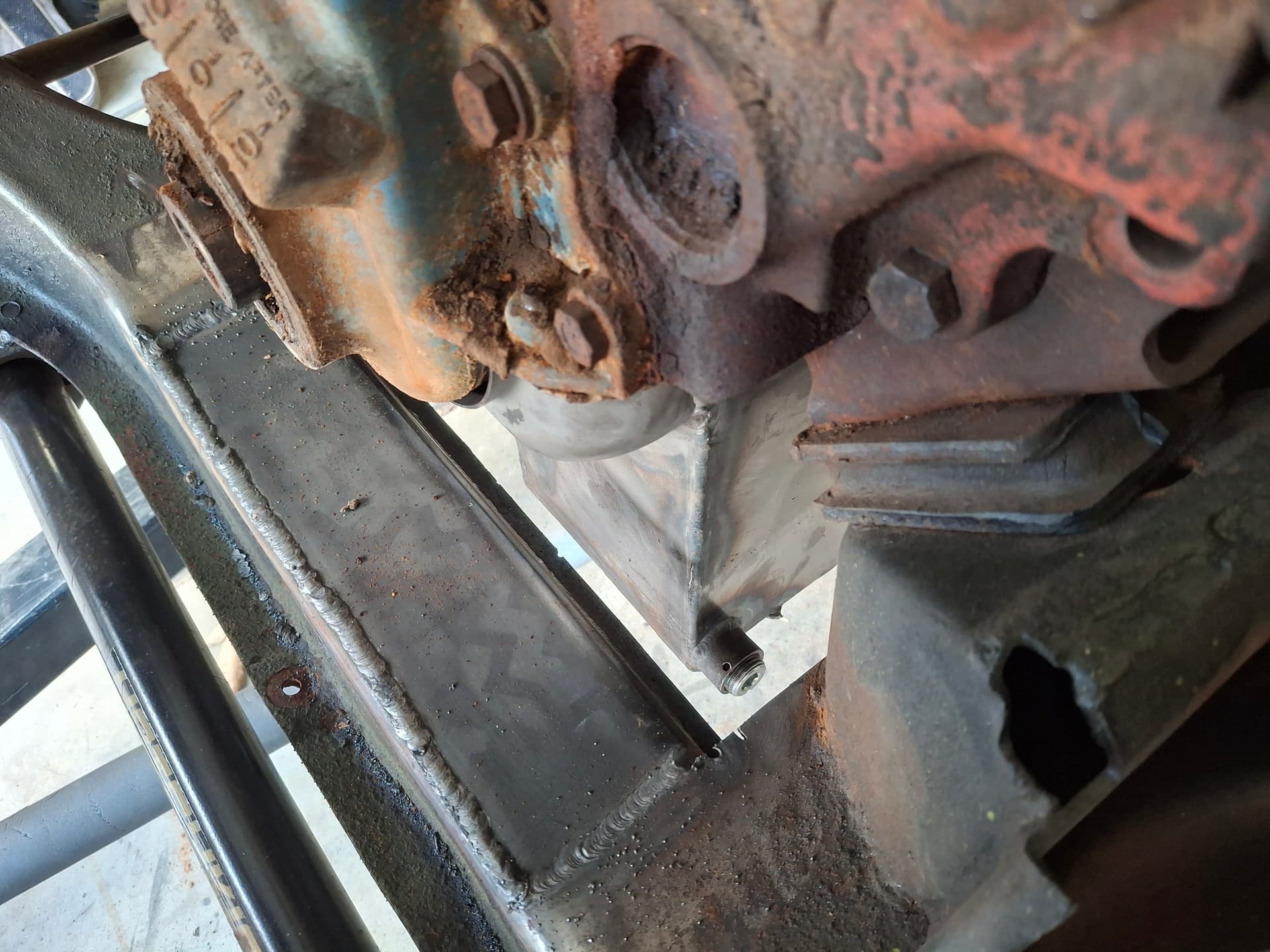
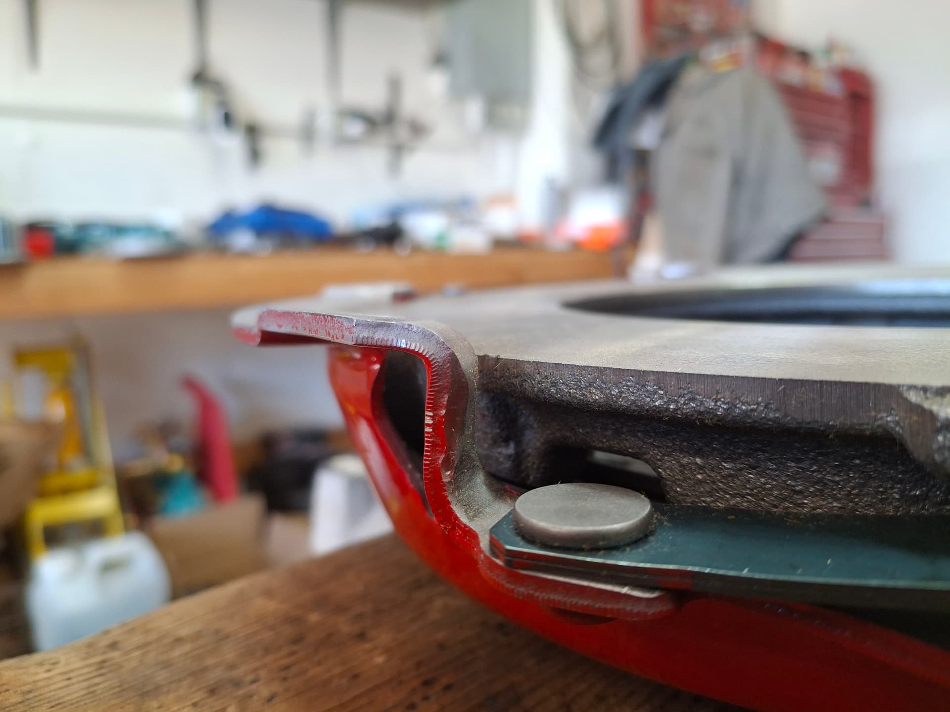
A visit to Keith Davidson’s got me thinking about the Barracuda’s cooling system–specifically the thermostat bypass hose that runs from the intake manifold to the water pump. In stock form, this 1" hose serves to stop air pockets from forming in the system when the thermostat is closed, keep the water pump from cavitating when the thermostat is closed, and to speed up the engine warming at cold start. The downside for a race engine is that the bypass functions at all times, meaning some coolant is not run through the radiator.

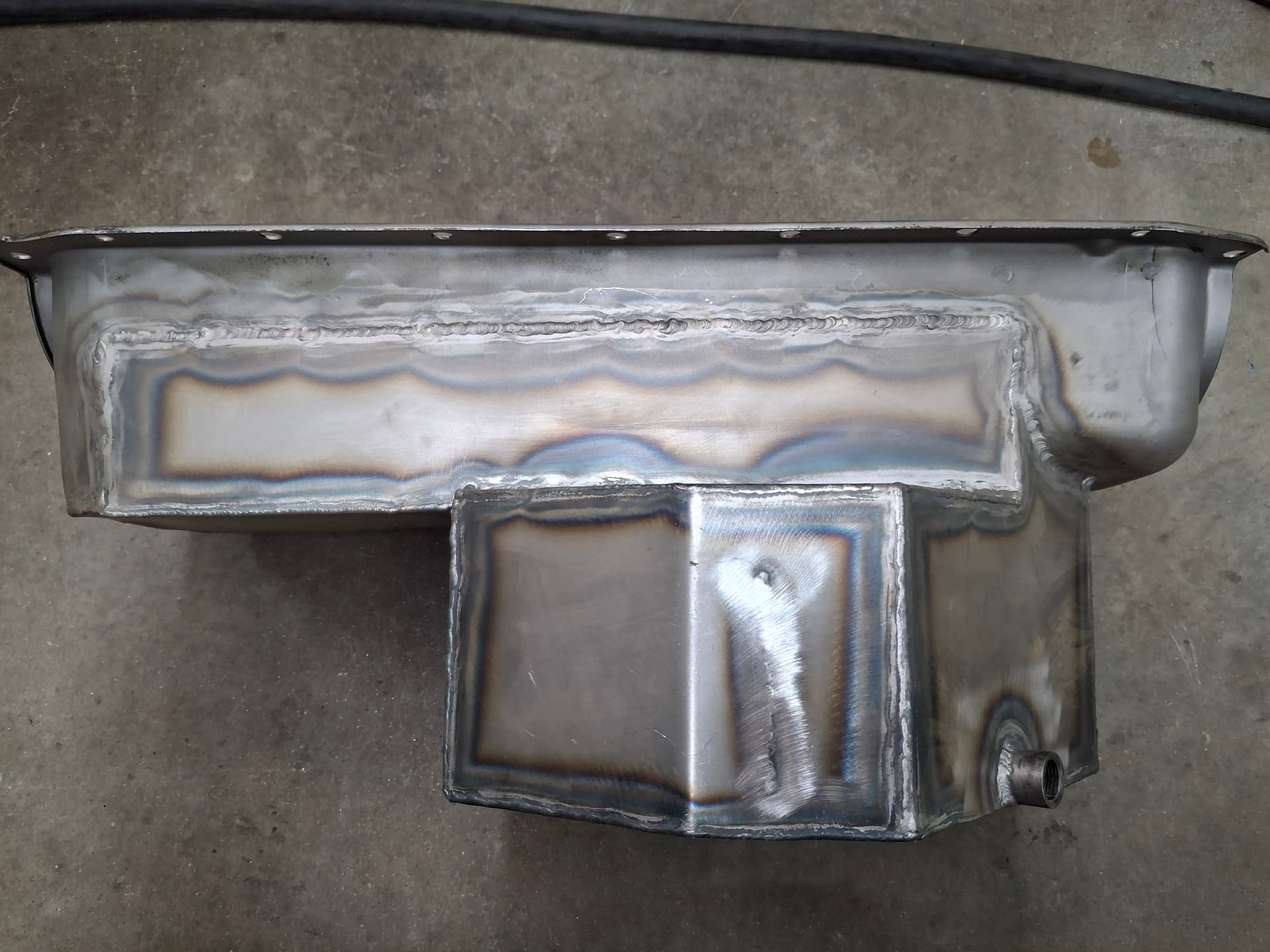
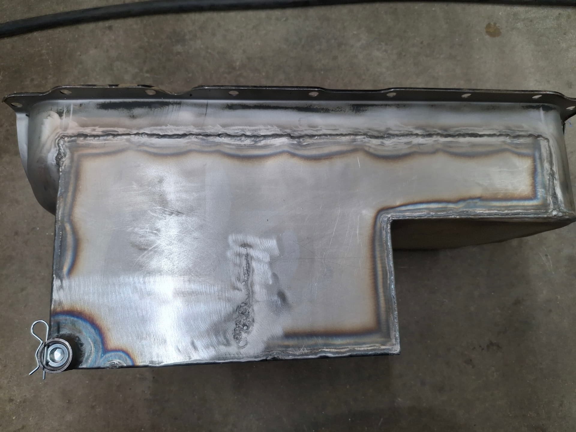
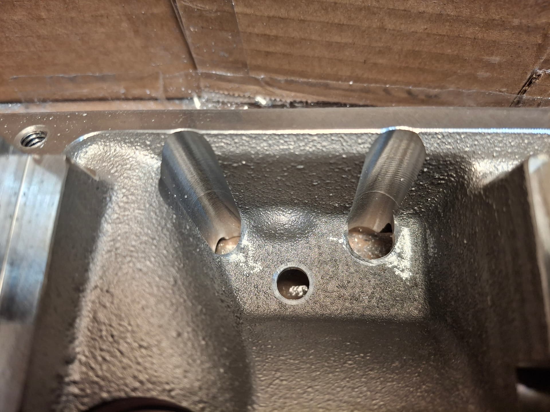
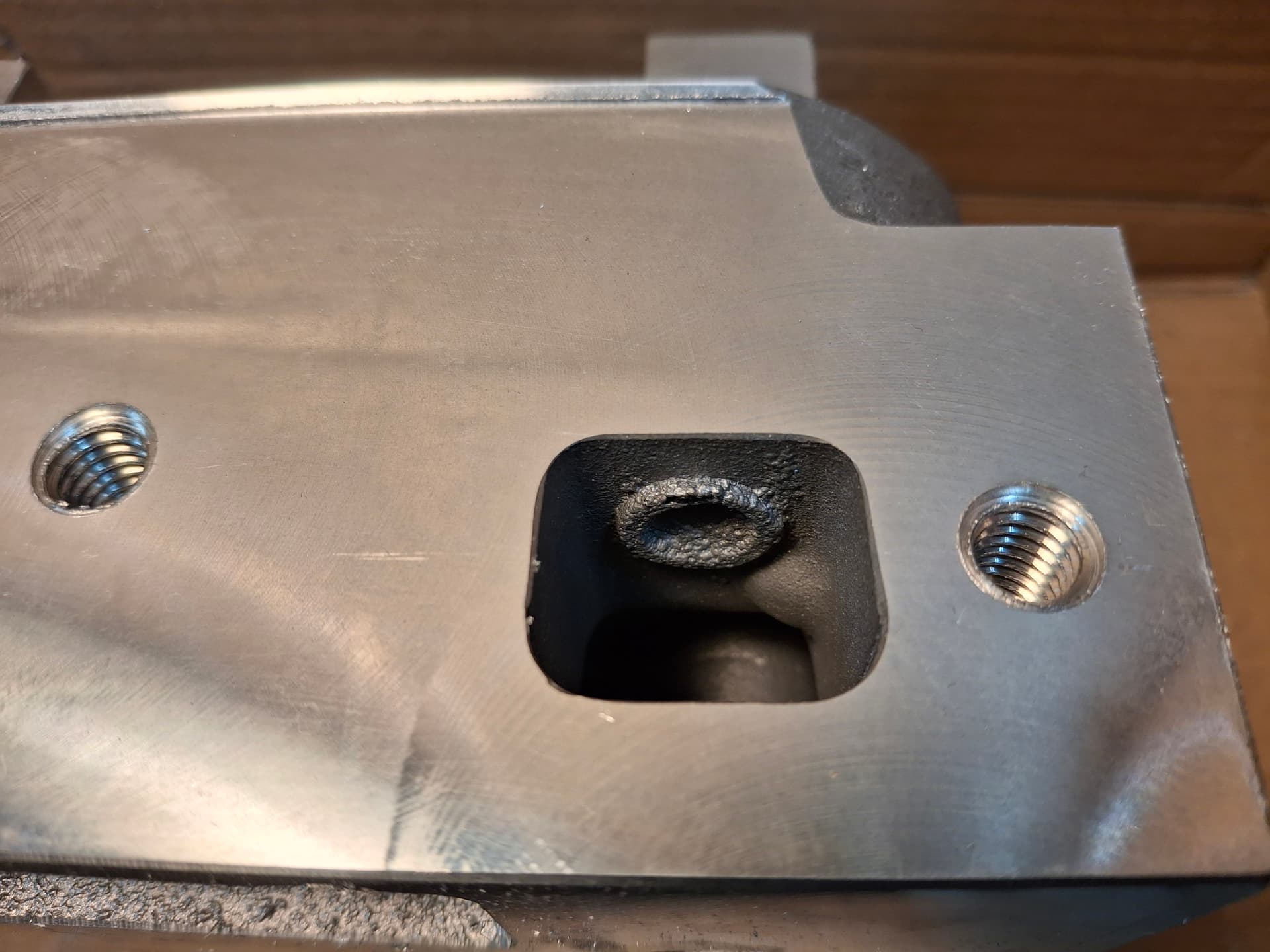
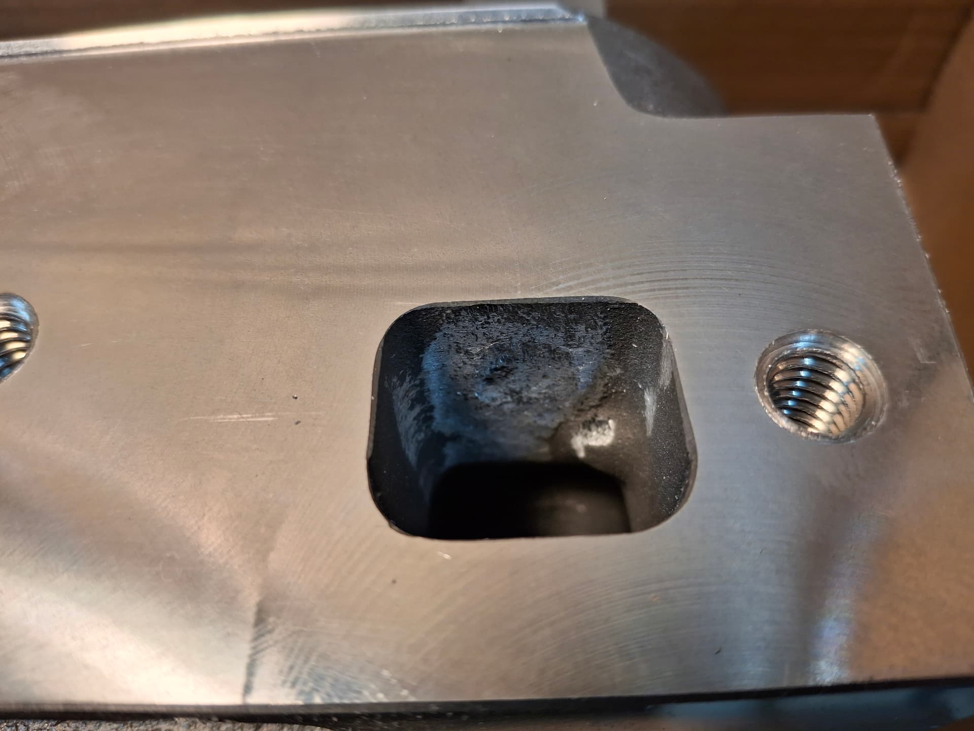
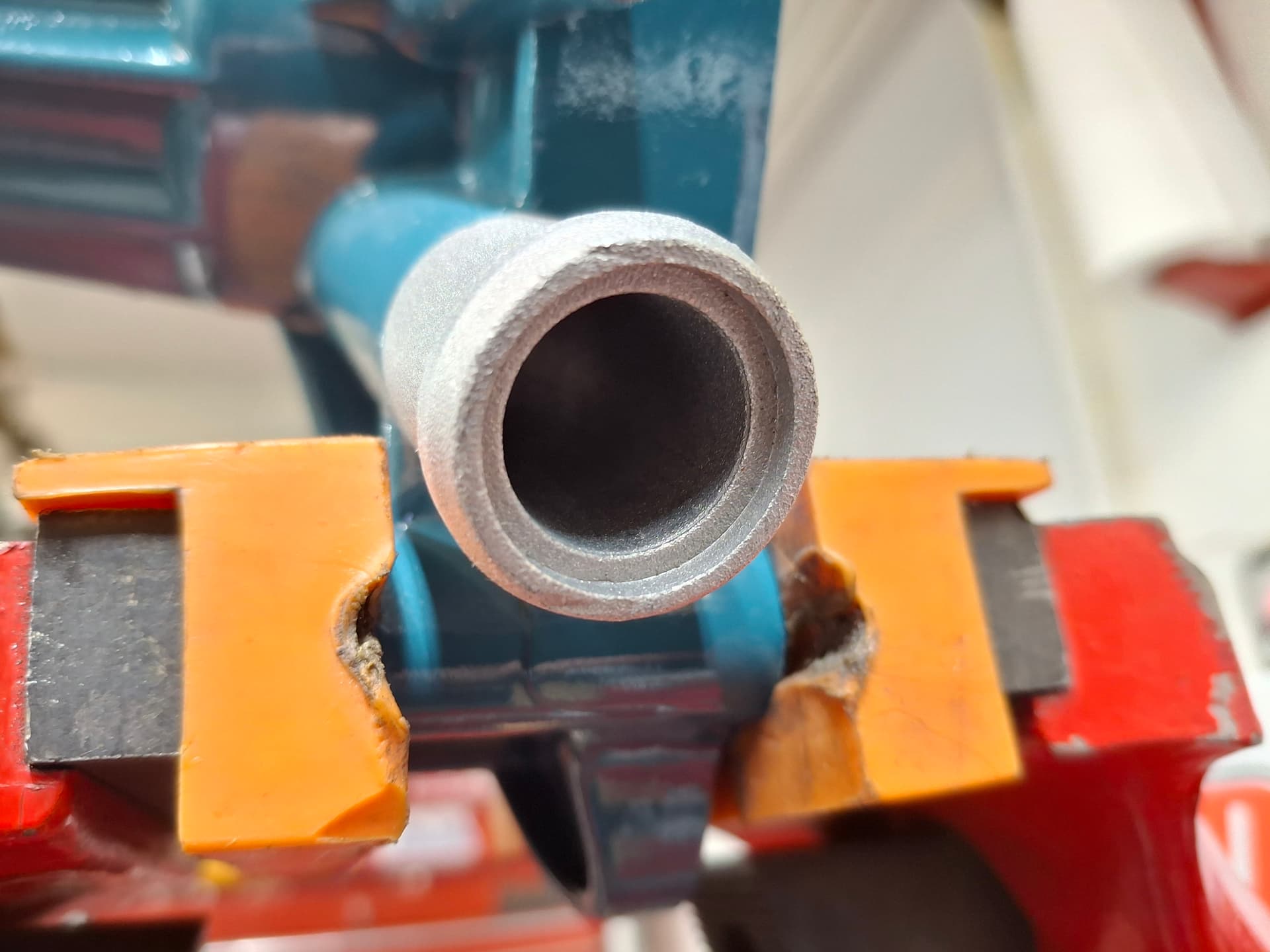
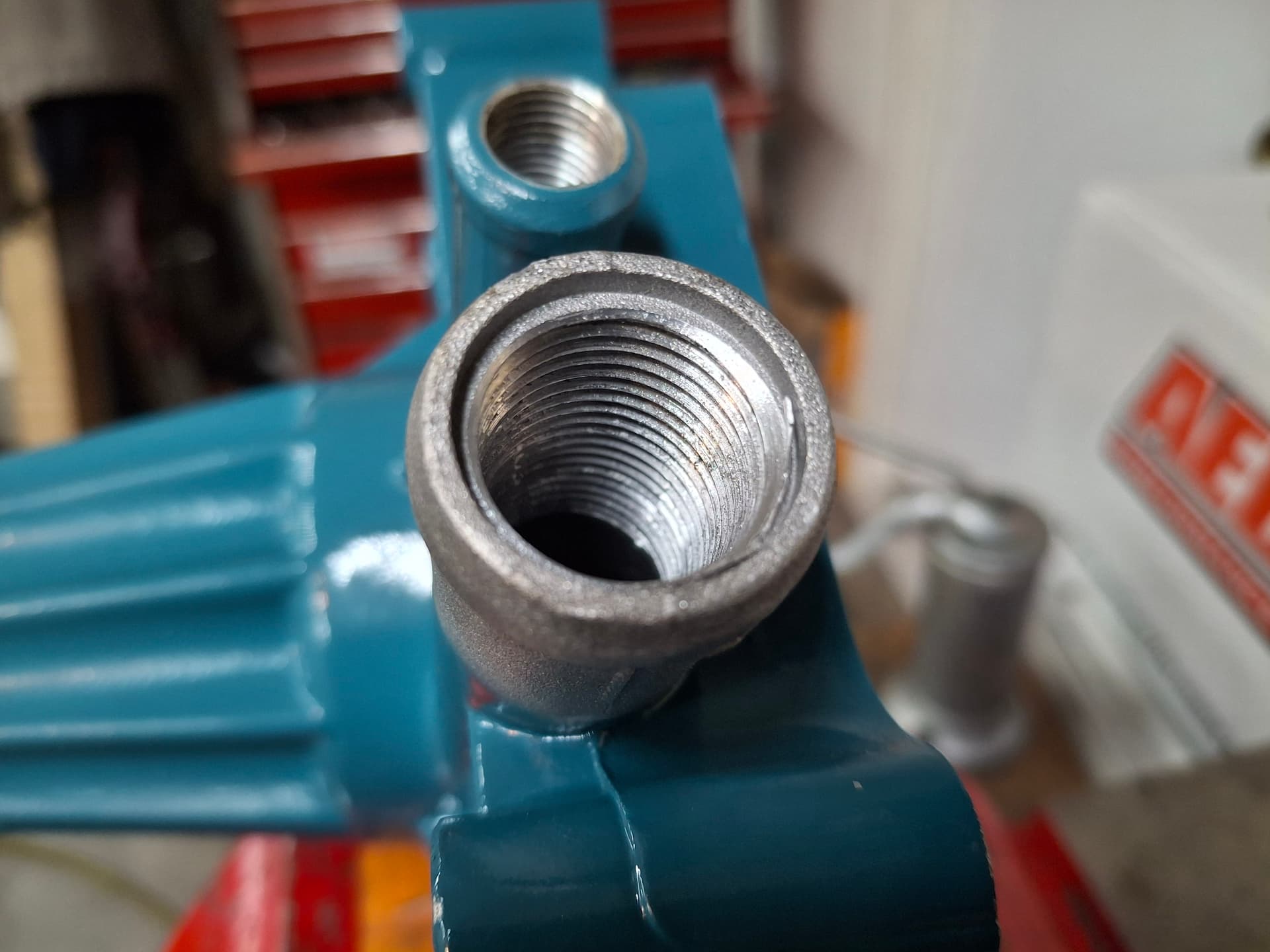
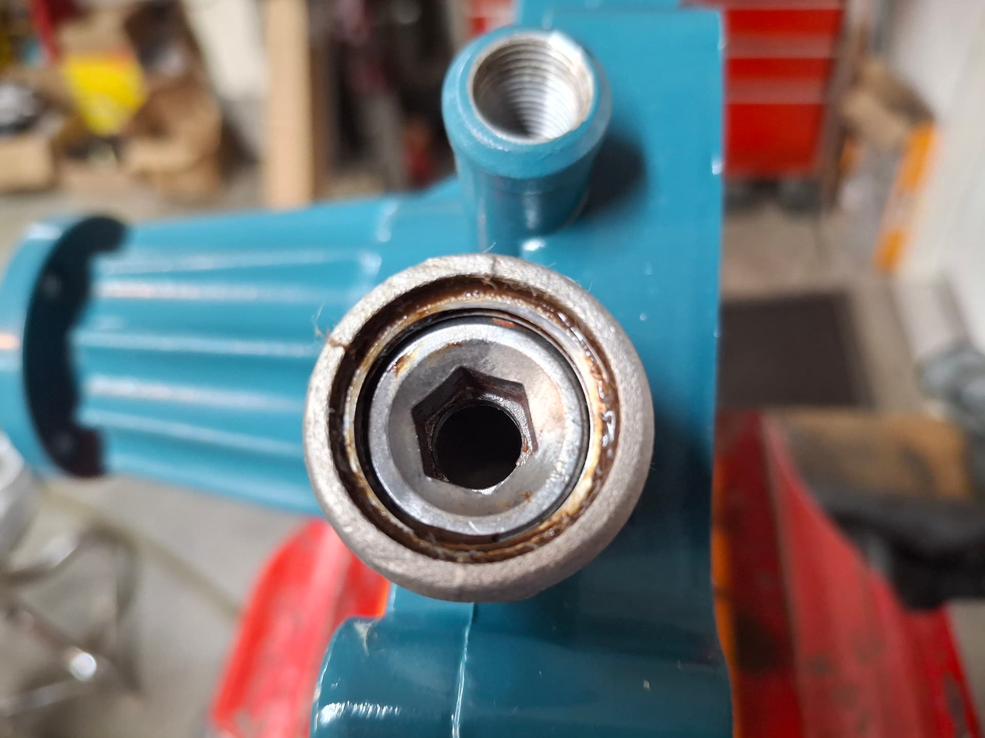
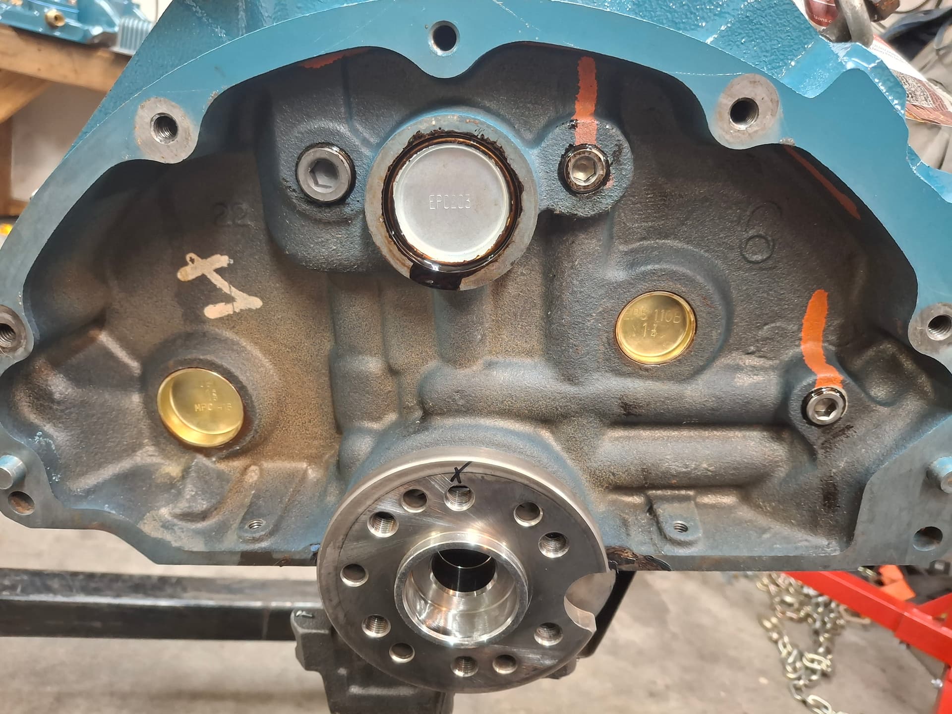
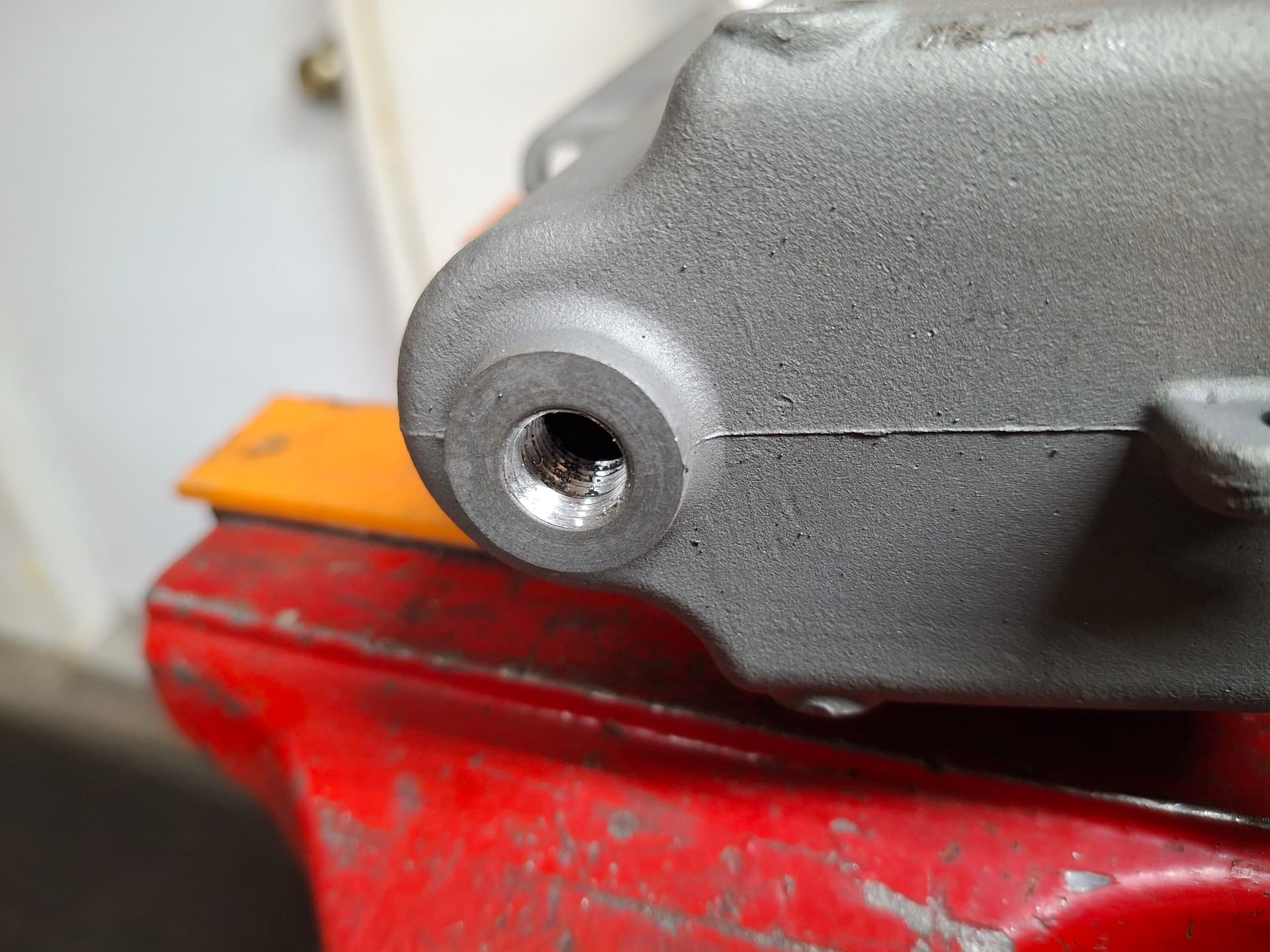
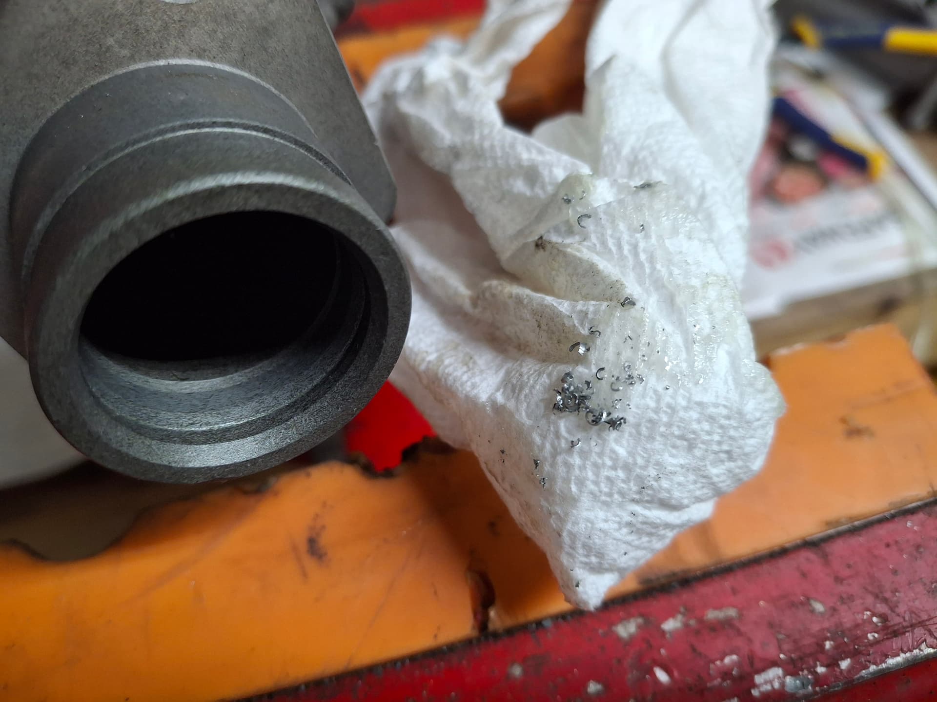
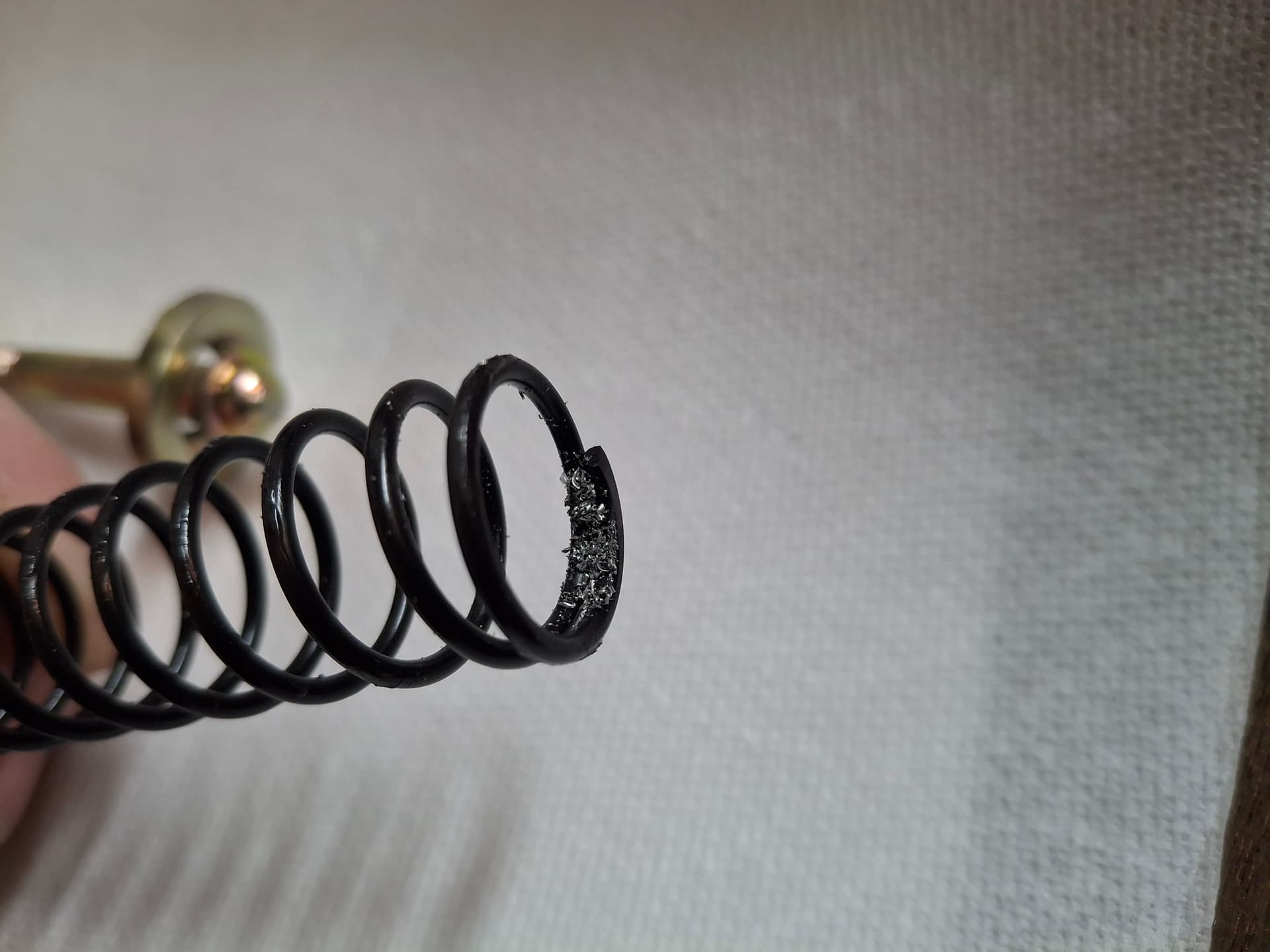
Keith mentioned to me that his Ford, which uses a smaller bypass hose but of a similar diameter, has a reducer in the bypass port to limit the volume of coolant that is always bypassed, thus forcing more coolant through the radiator. After doing some research, I found that only 0.06 square inches of area is needed as a bypass to keep the air pockets from forming and the pump from cavitating while the thermostat is closed, which many people get by drilling two 3/16" holes in the thermostat plate. Instead, I drilled and tapped the inside of the nipple in the water pump to 1/2" NPT. I drilled a 5/16" hole through a stainless-steel pipe plug to provide 0.076 square inches of surface area, and I installed the pipe plug into the nipple with sealant.

Cylinder Head and Intake Port Matching and Machining
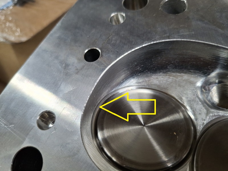
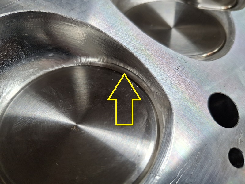
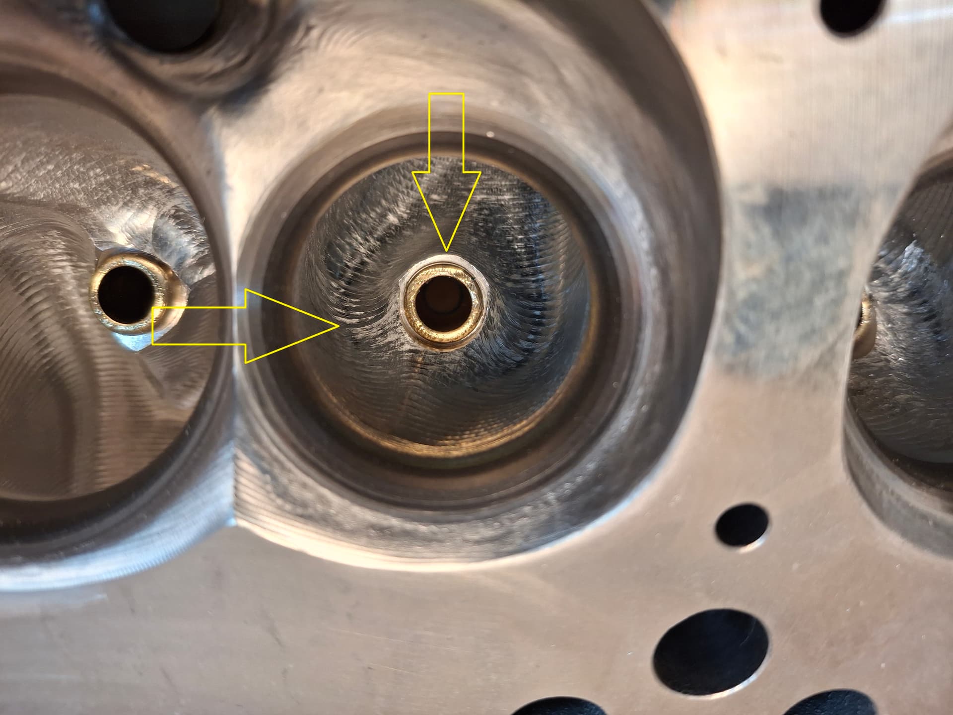
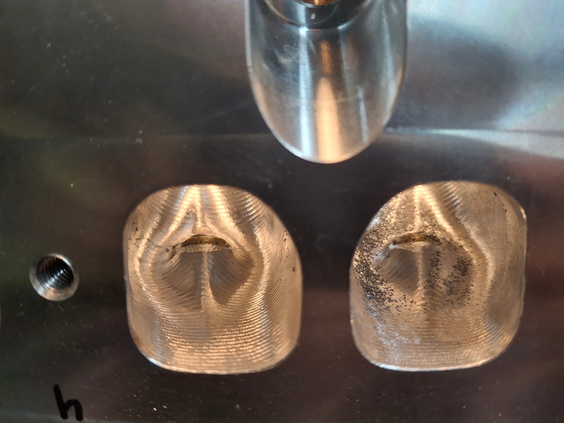
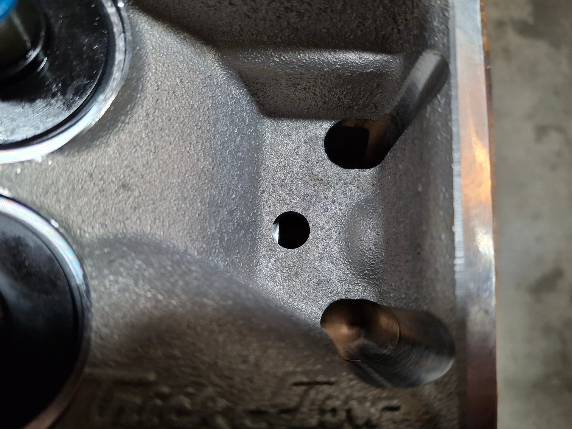
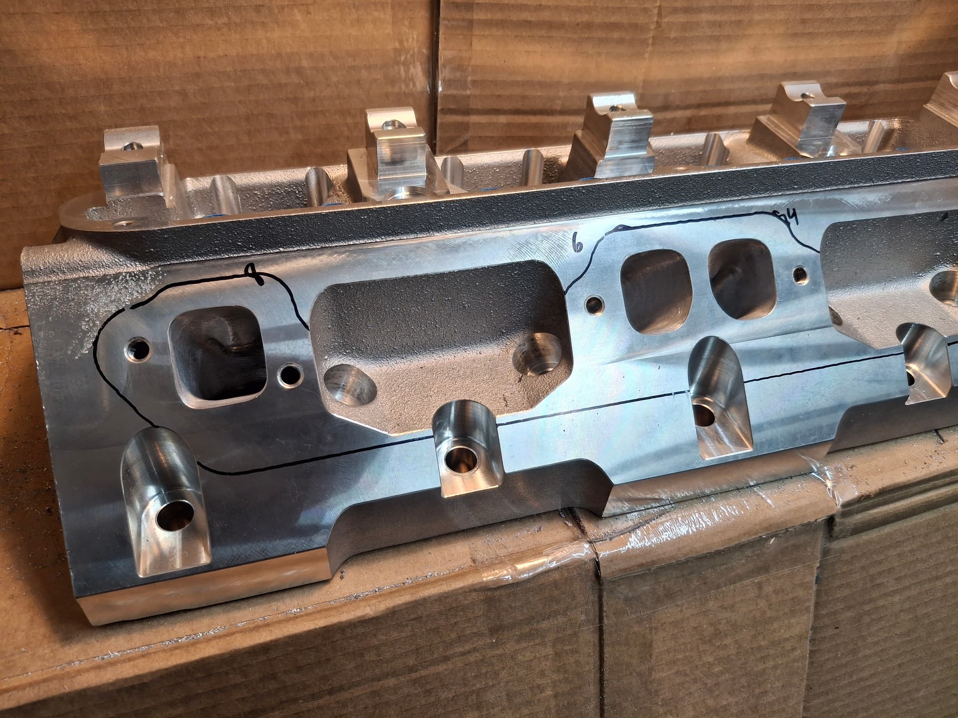
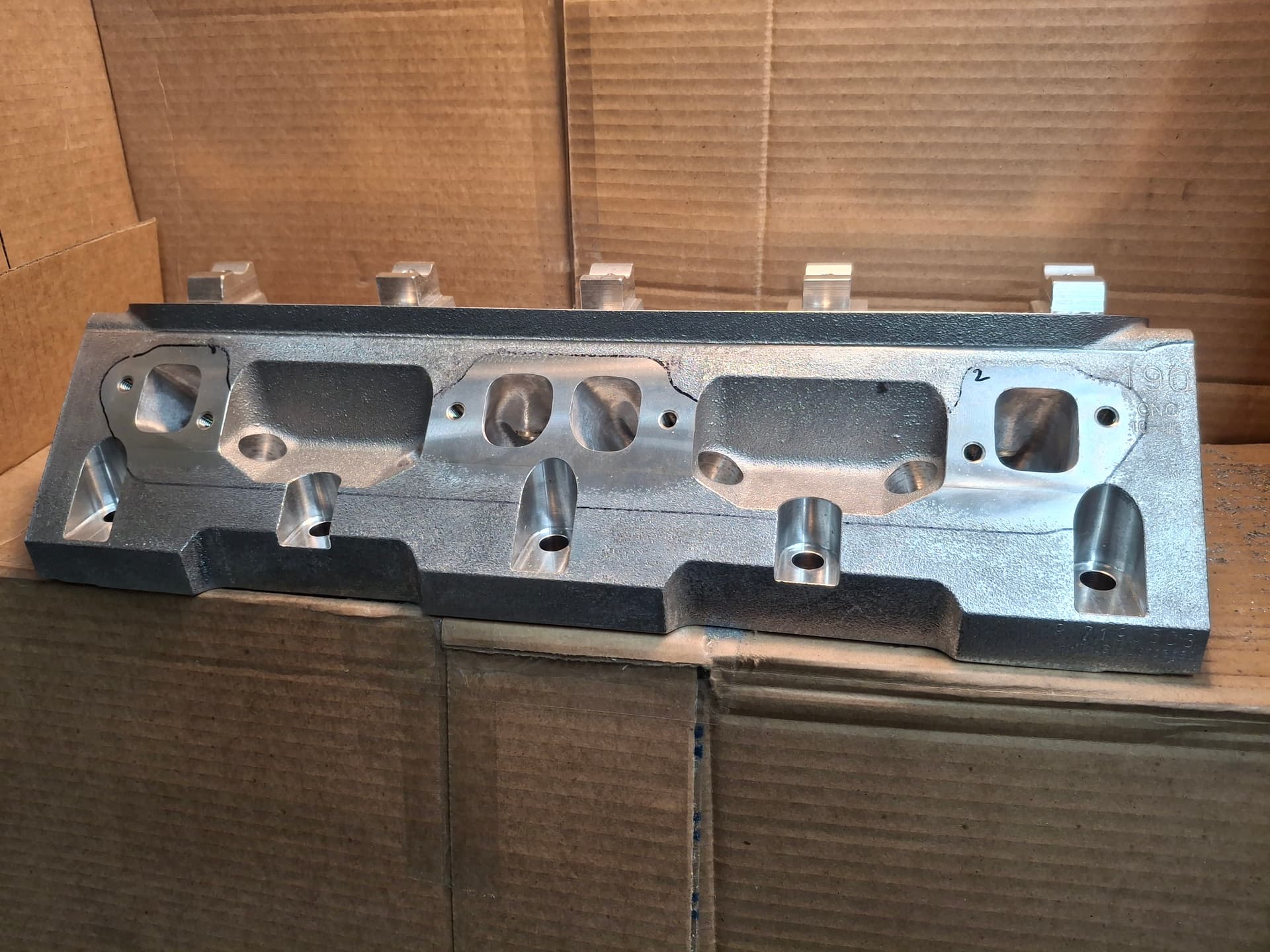
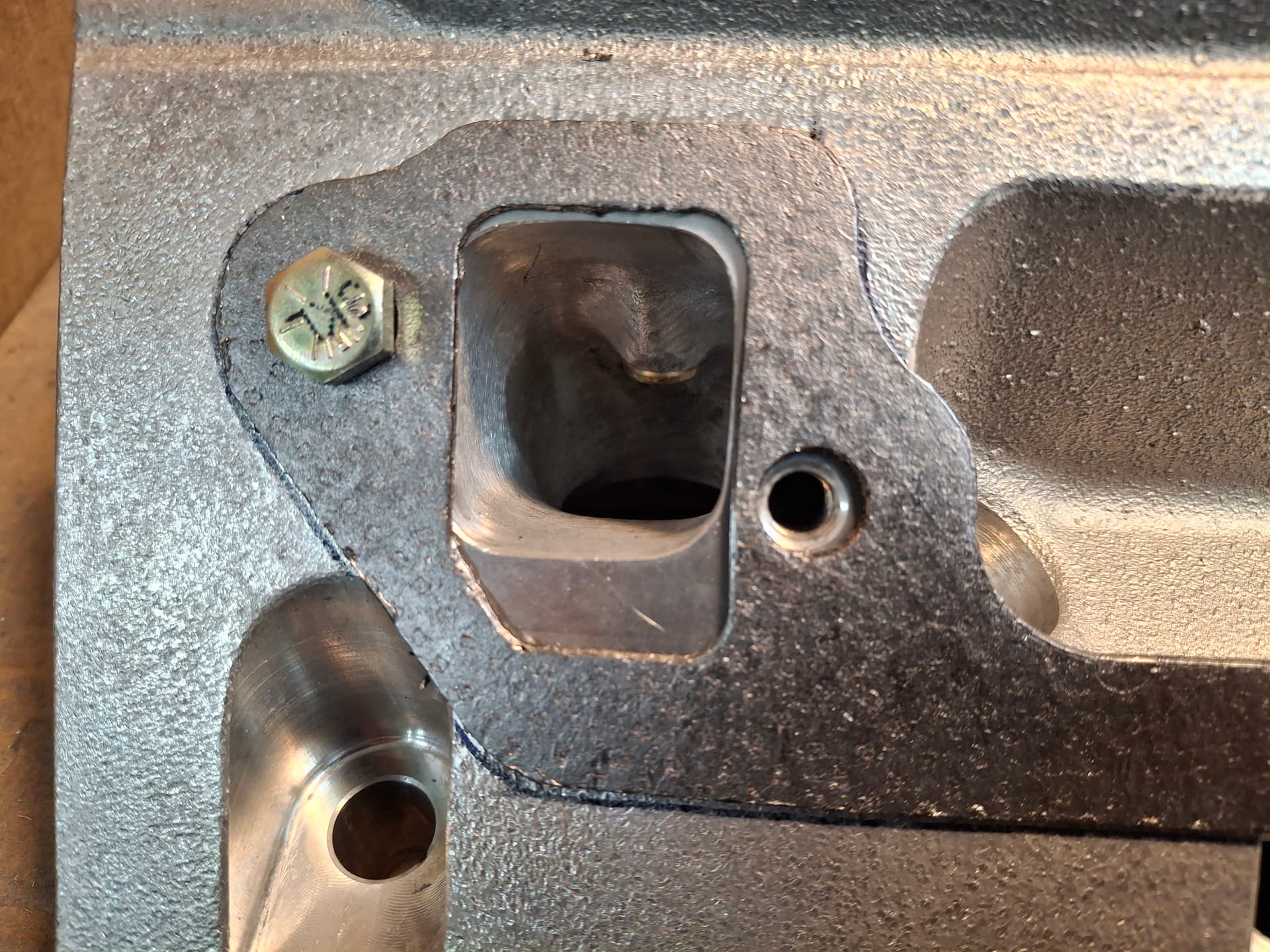
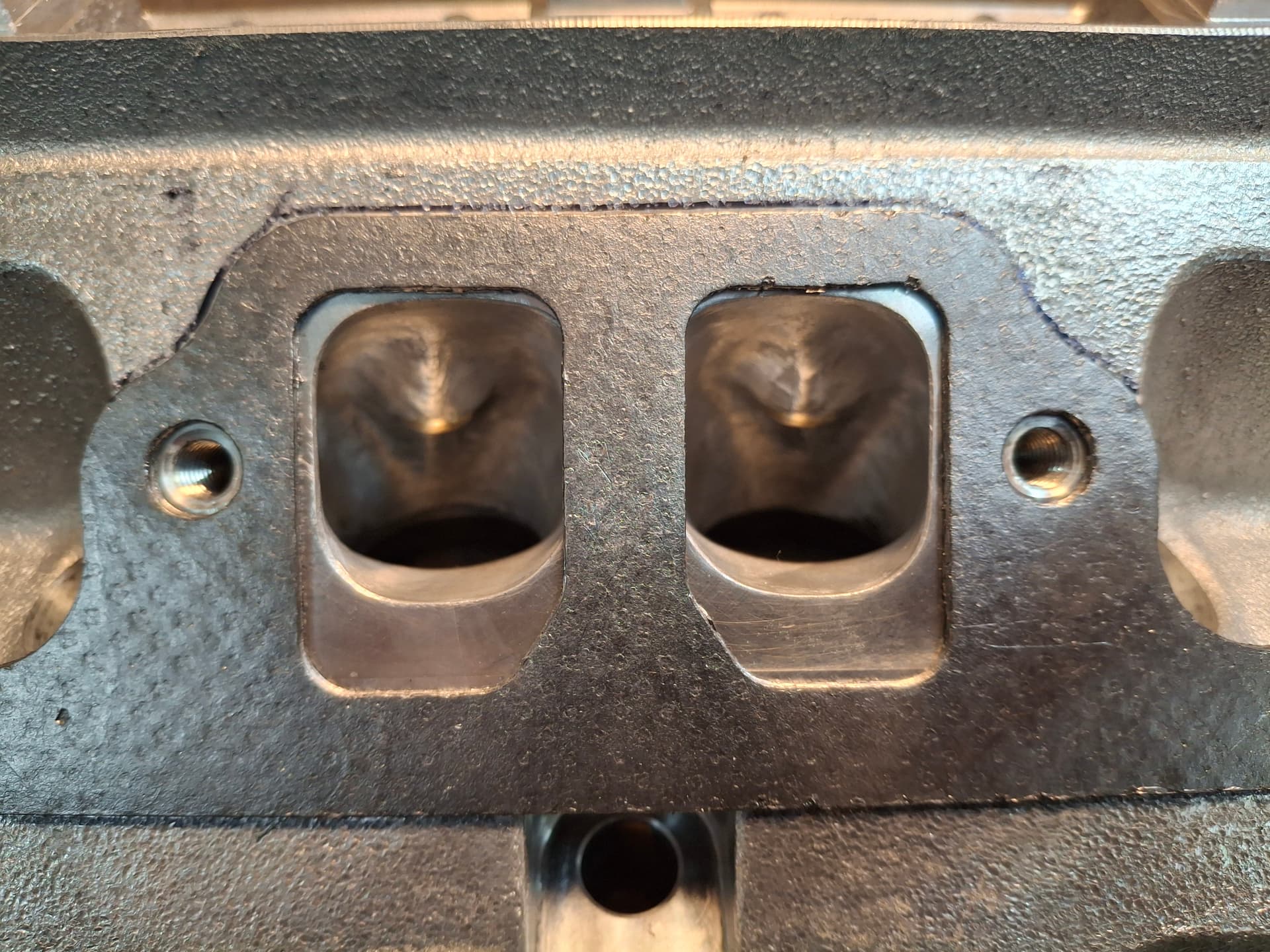
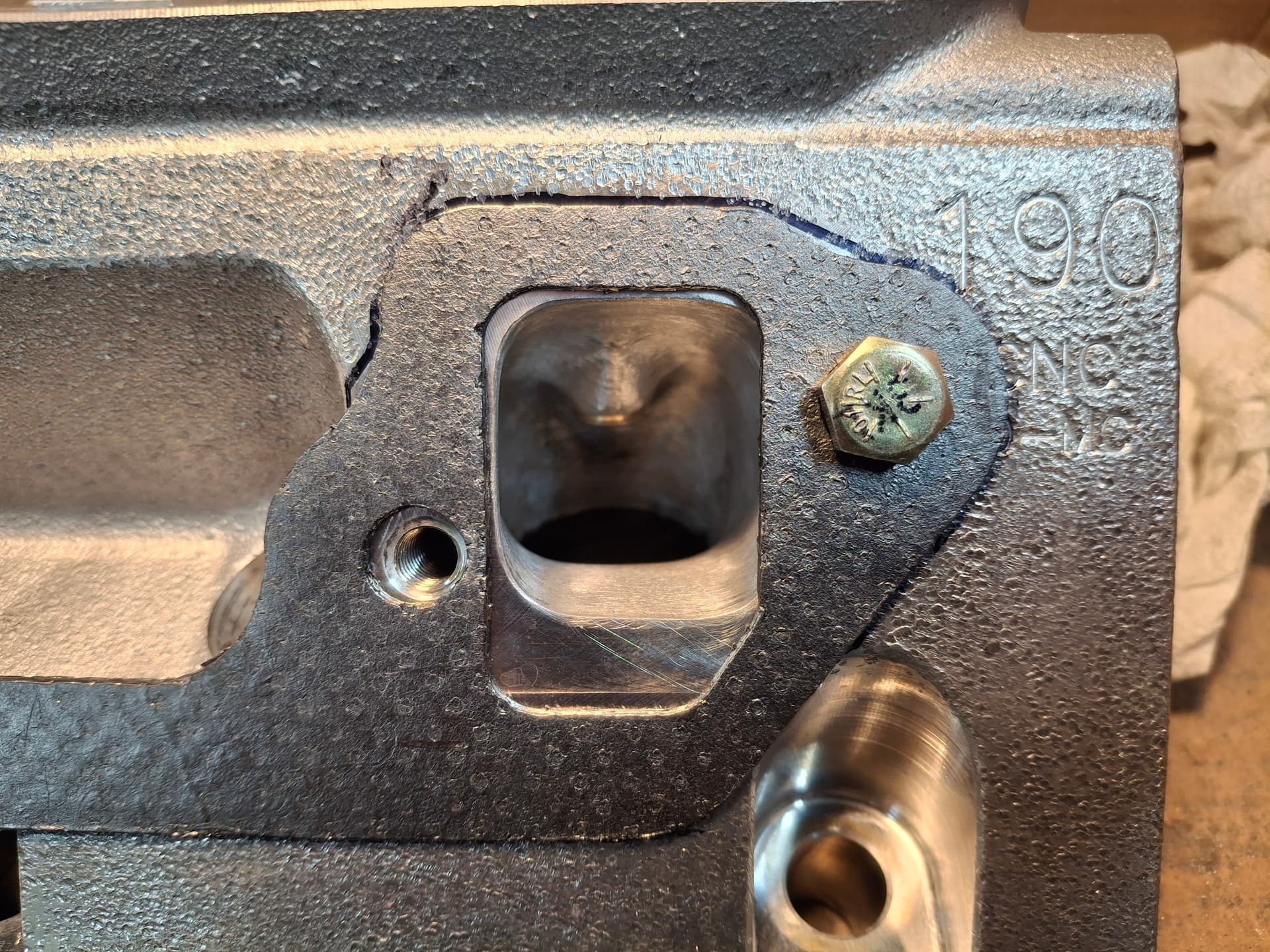
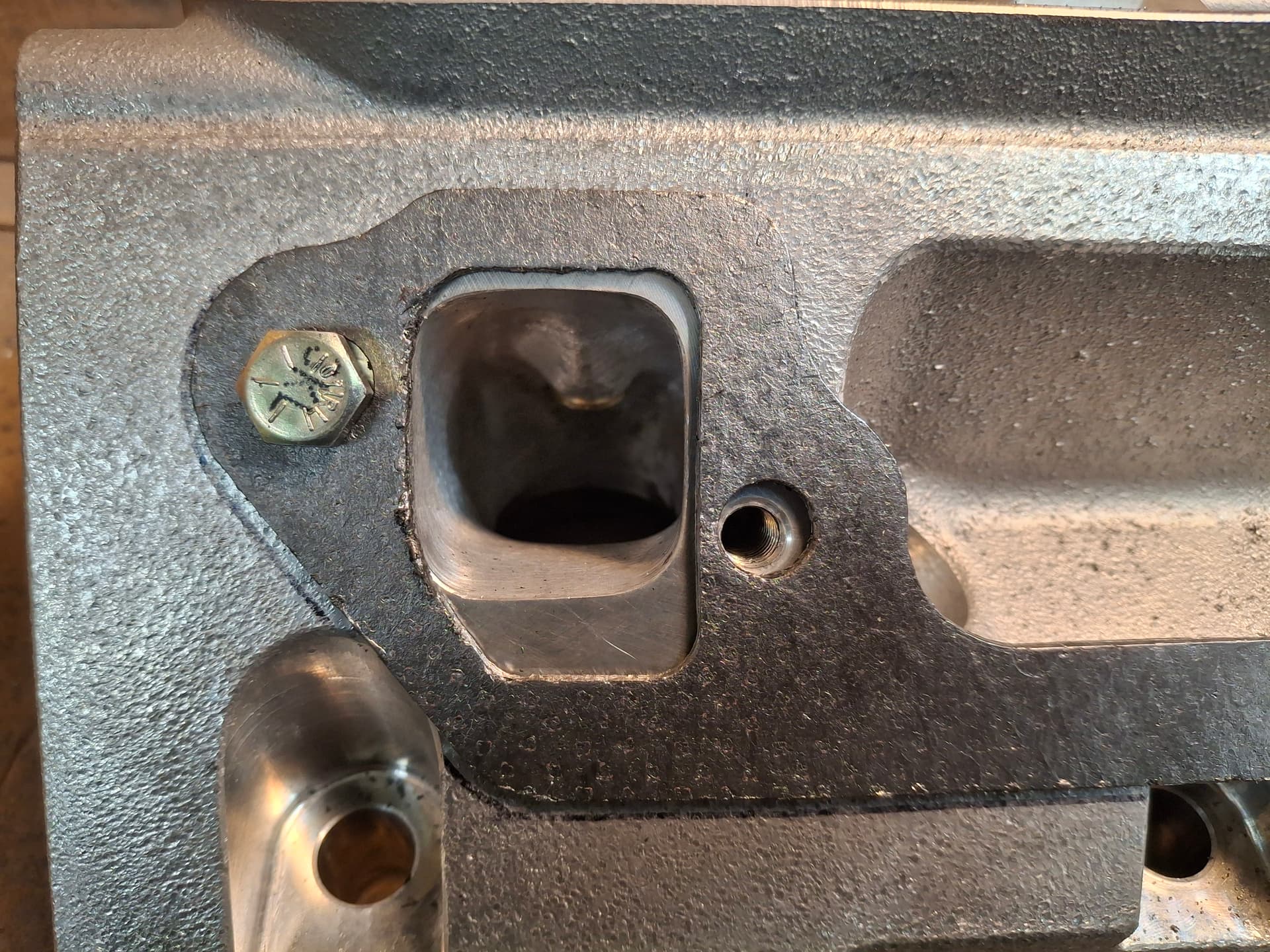
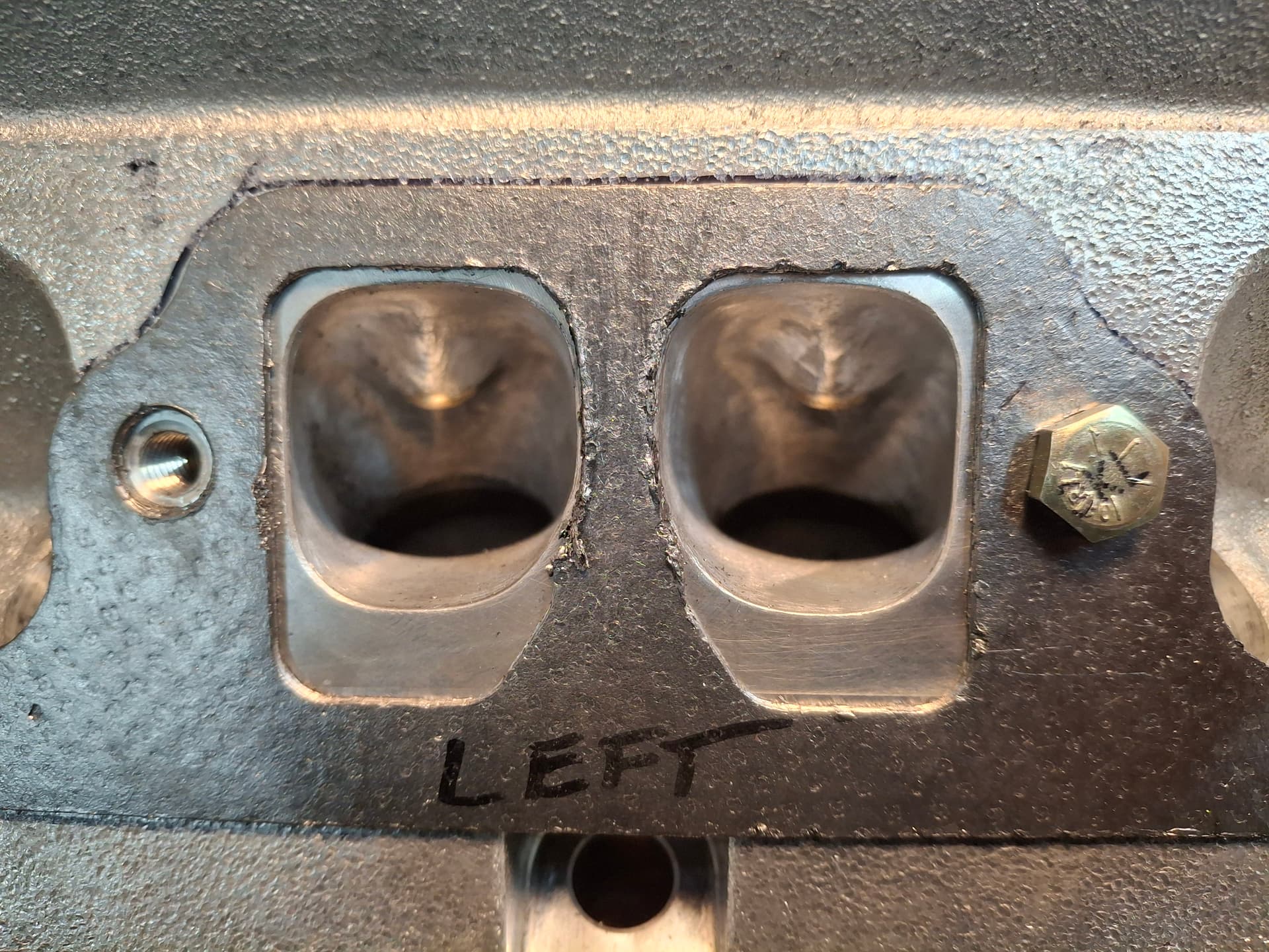
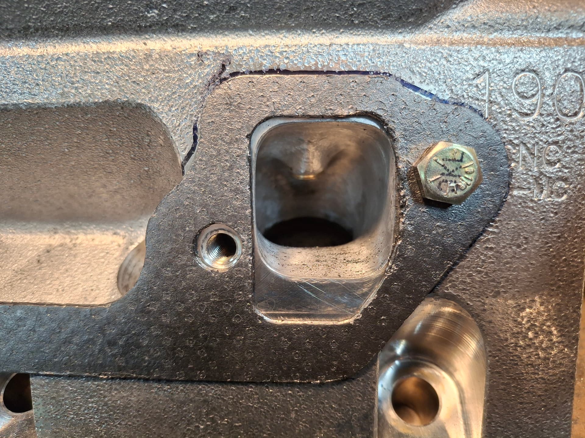
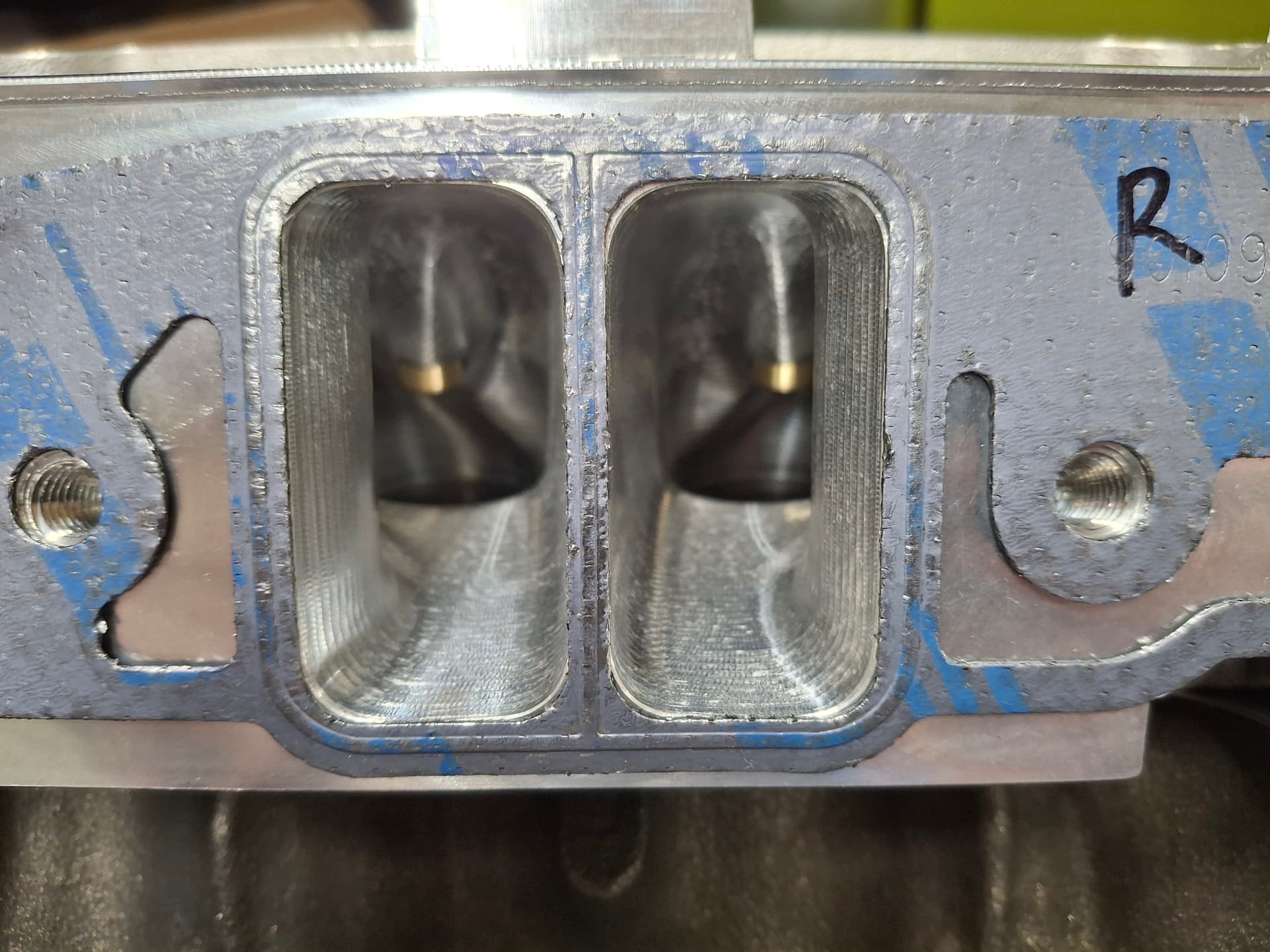
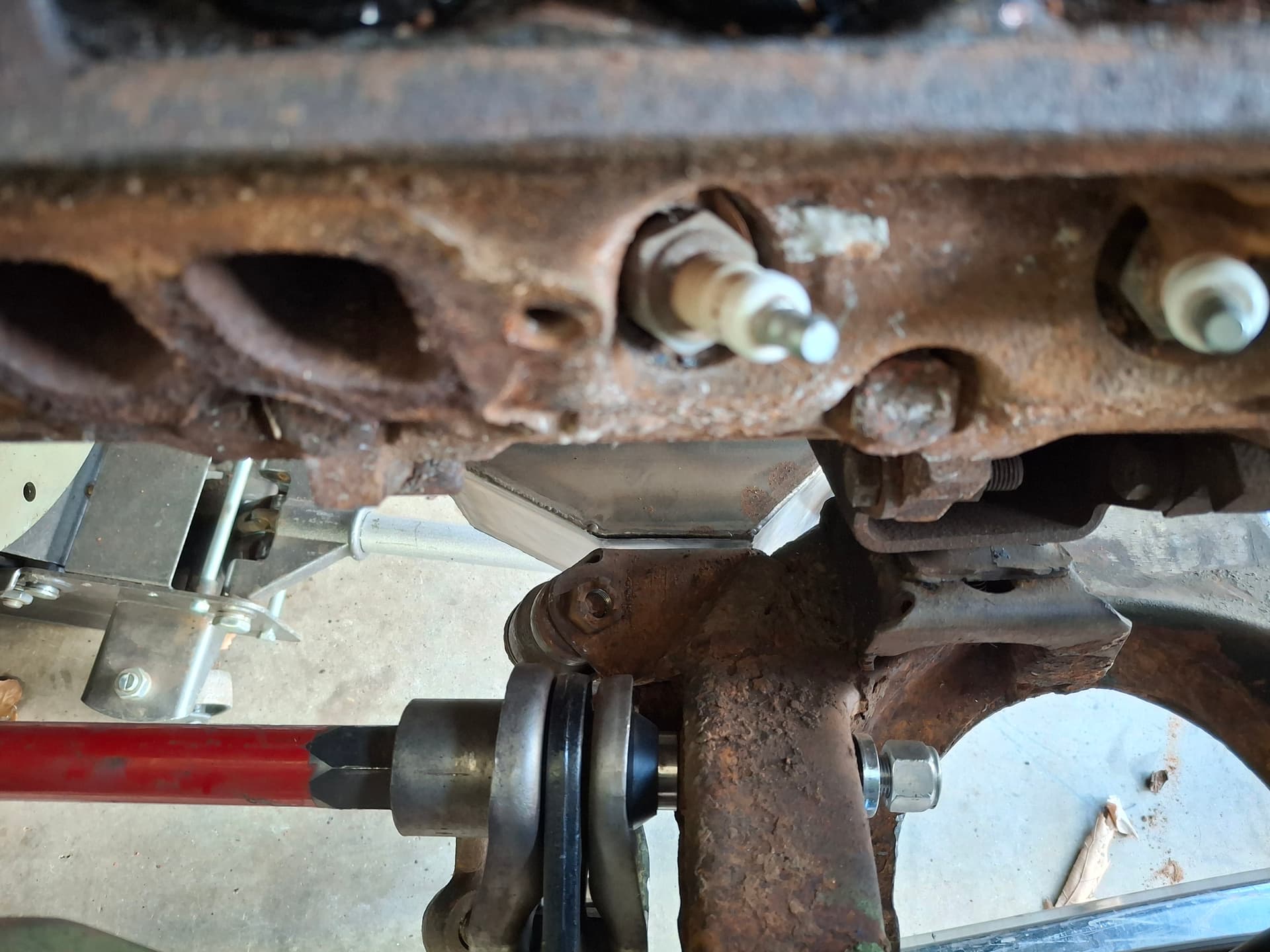
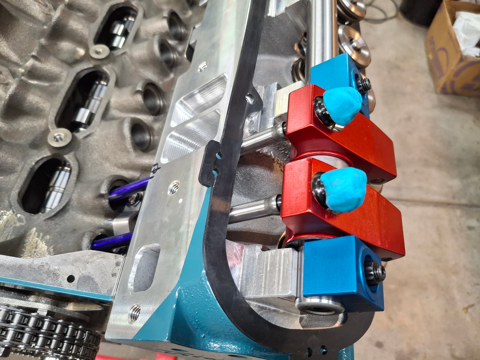
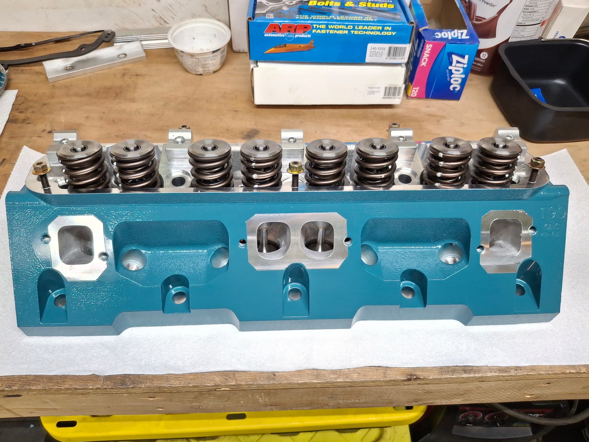
I bolted the exhaust gaskets to the heads and found that I didn’t need to do any work to the heads, but some of the gasket overhung the head port. I marked the spots and enlarged the gasket ports with a burr bit. As you can see, the head ports are round while the header ports are rectangular, but this is by design since the round head ports flow much better than the low-performance factory heads that use rectangular ports.

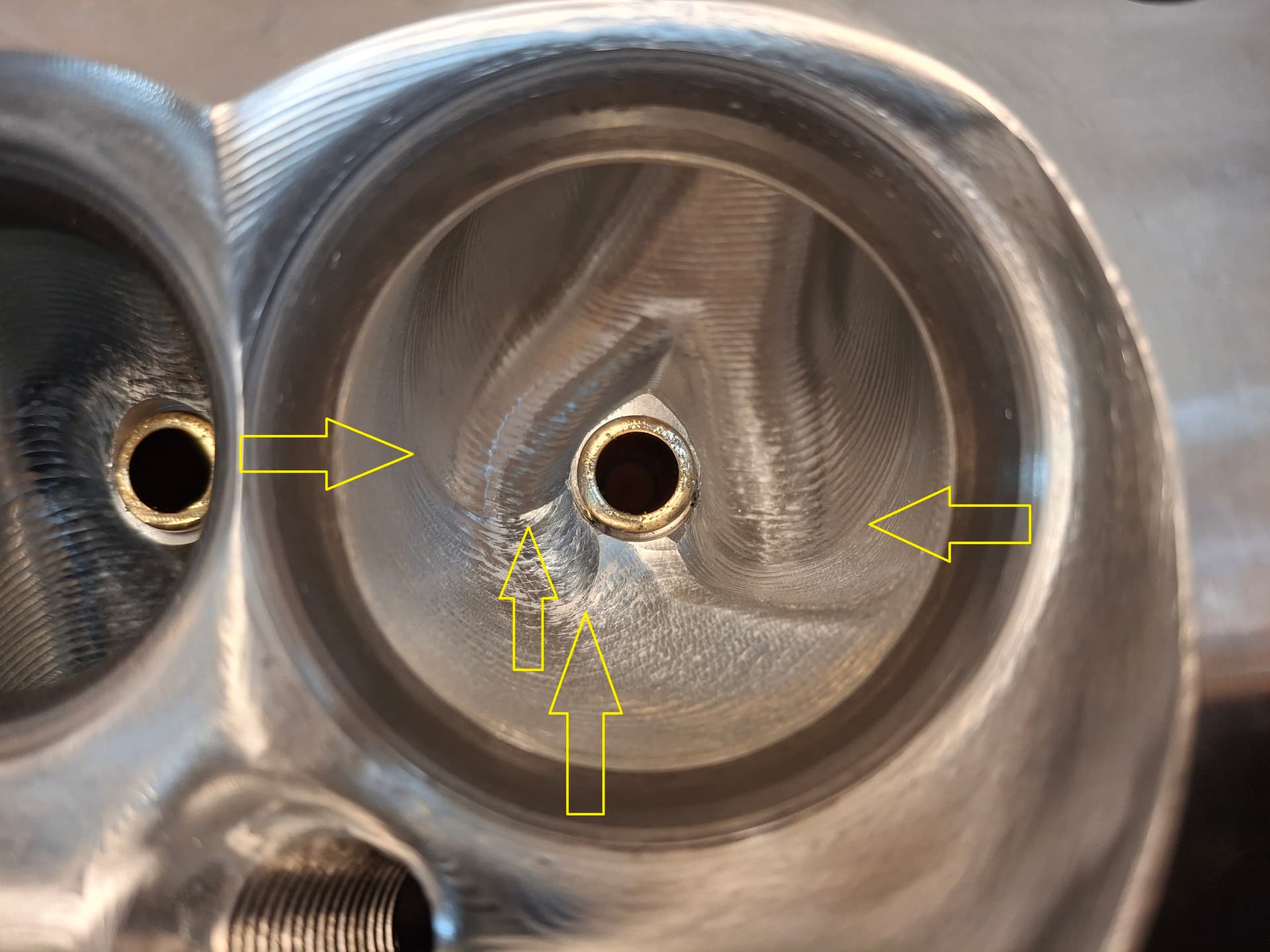
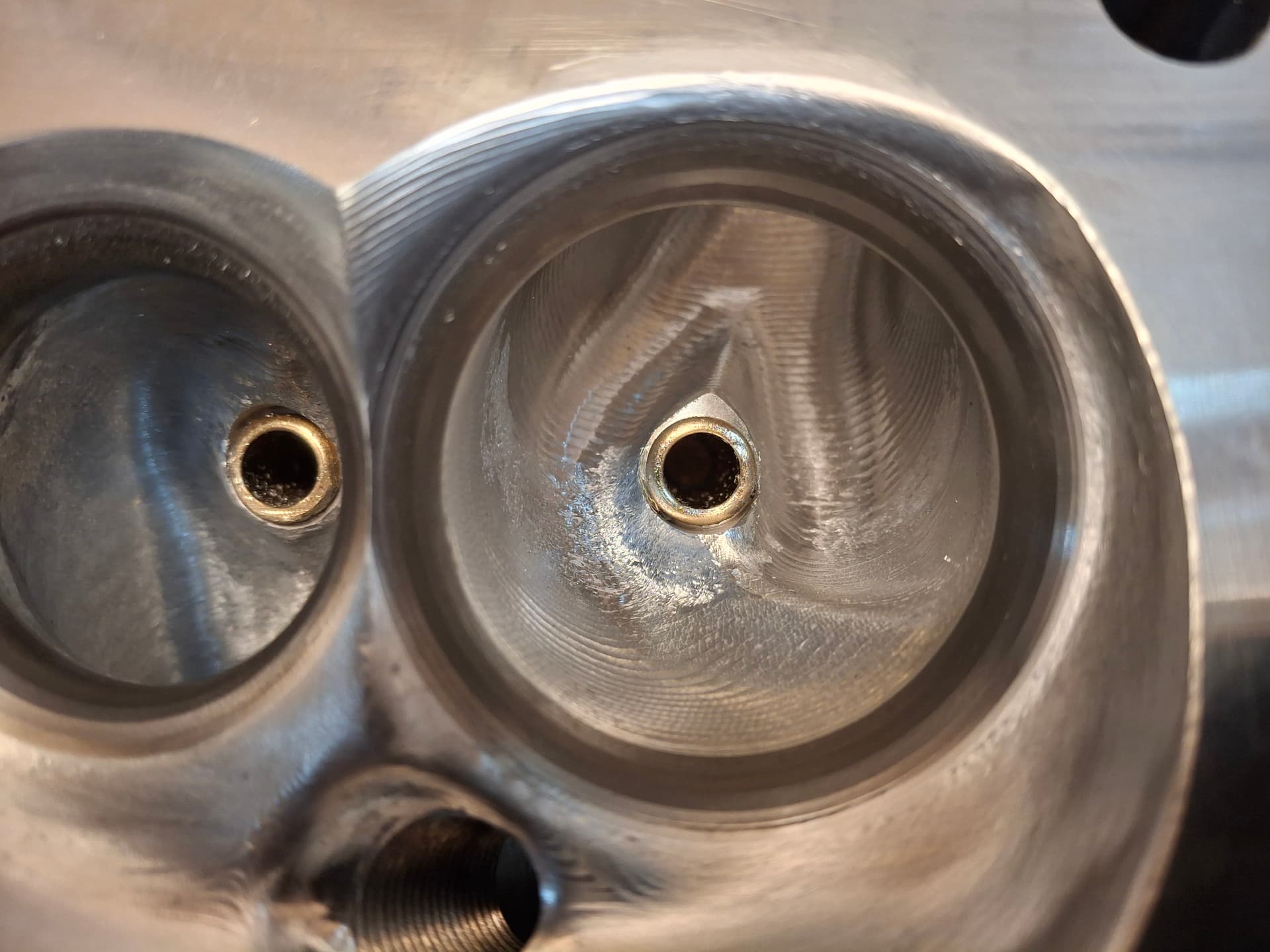
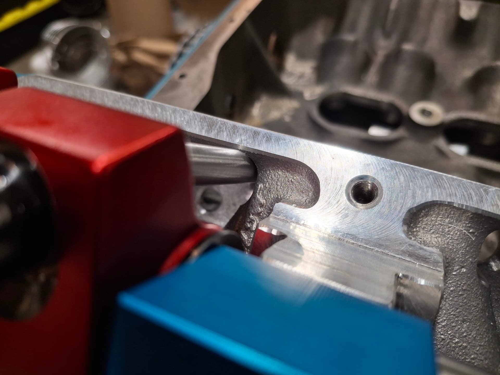
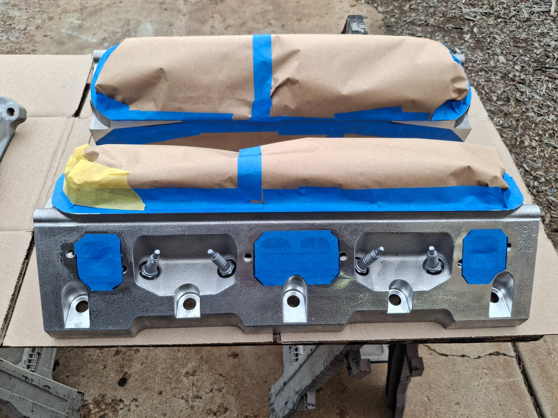
I installed the head gaskets and heads, snugging them down enough to not crush the gaskets but clamp down the heads. I positioned the intake gaskets on the heads and taped them in place. The heads’ intake runners would require some massaging to match the gasket, and the gasket would need some massaging to match the ports. I then installed the intake manifold and tightened its bolts just enough to snug down the intake but not crush the gasket.

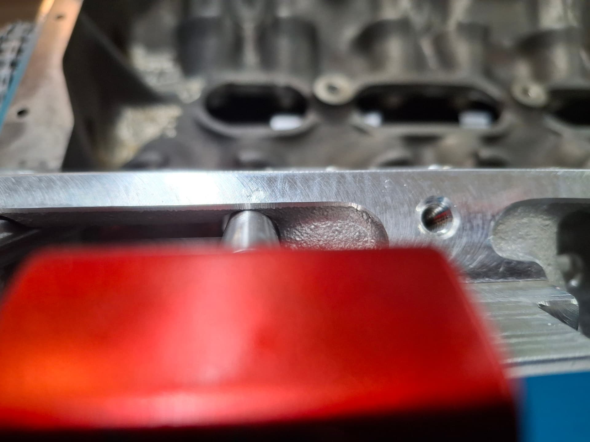
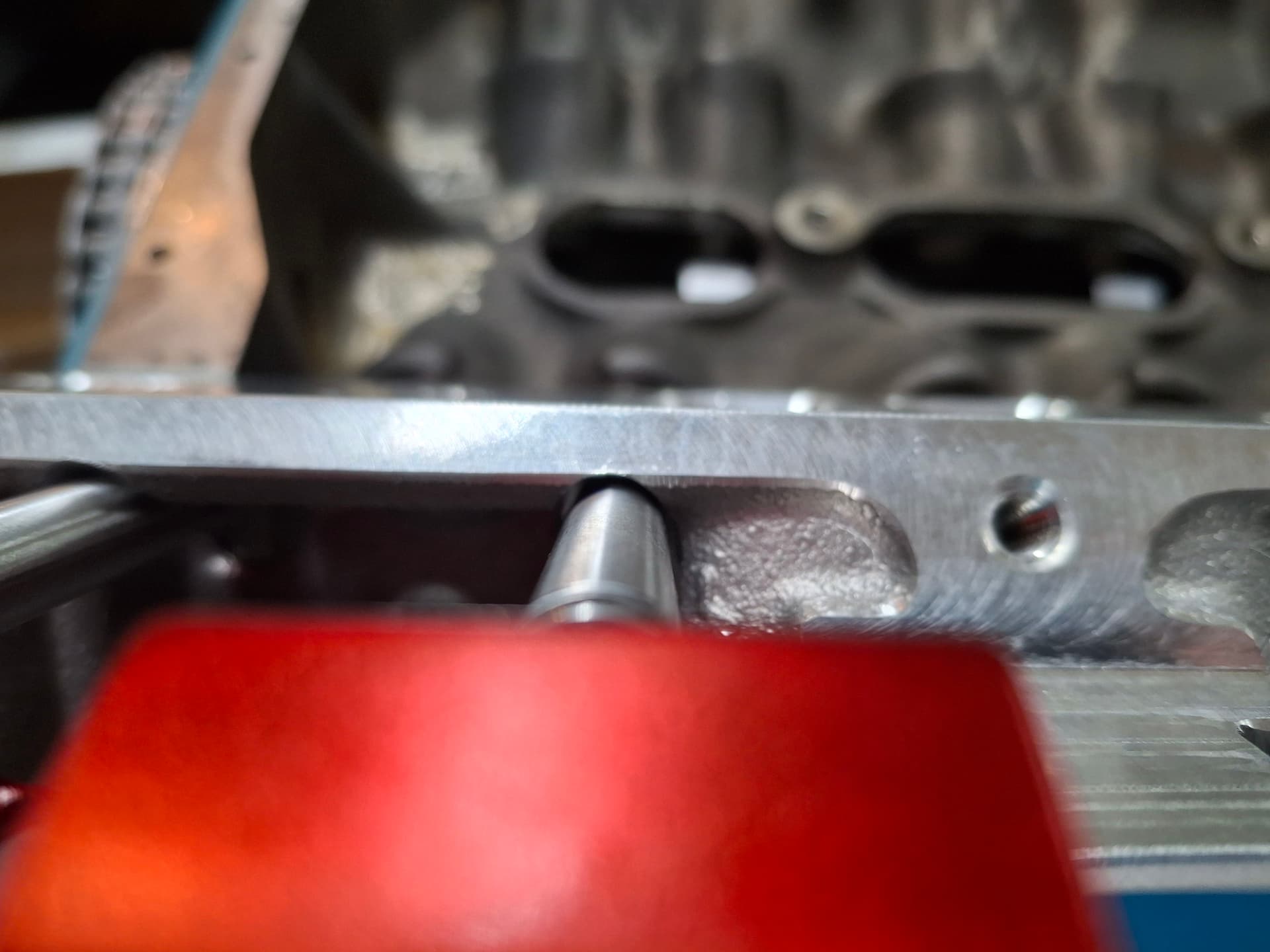
I used a 1/8" drill bit to drill at each corner through the intake, through the gasket, and approx. 1/8" deep into the head in locations that are not critical for air/coolant in order to index the gaskets. Of course, as with most well-laid plans of mice and men, the drill locations I chose did not cleanly go through the gasket but skirted an area void of gasket, but there was enough indexing for my purposes.

I scribed the lines on the head and used marker on the gaskets for trimming, removed the intake and heads from the block, and machined the head and gasket with a burr bit.

Intake Manifold Machining

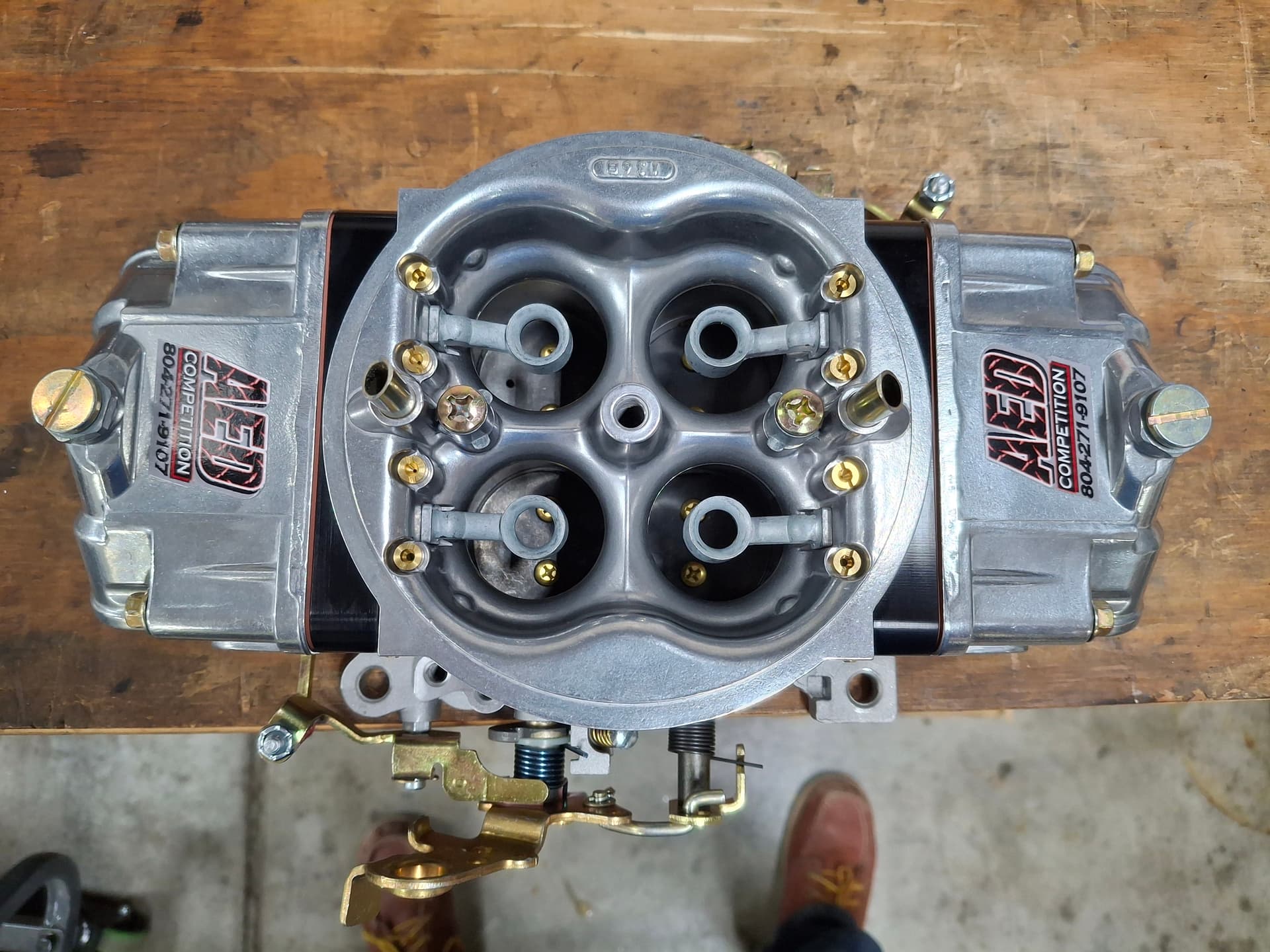
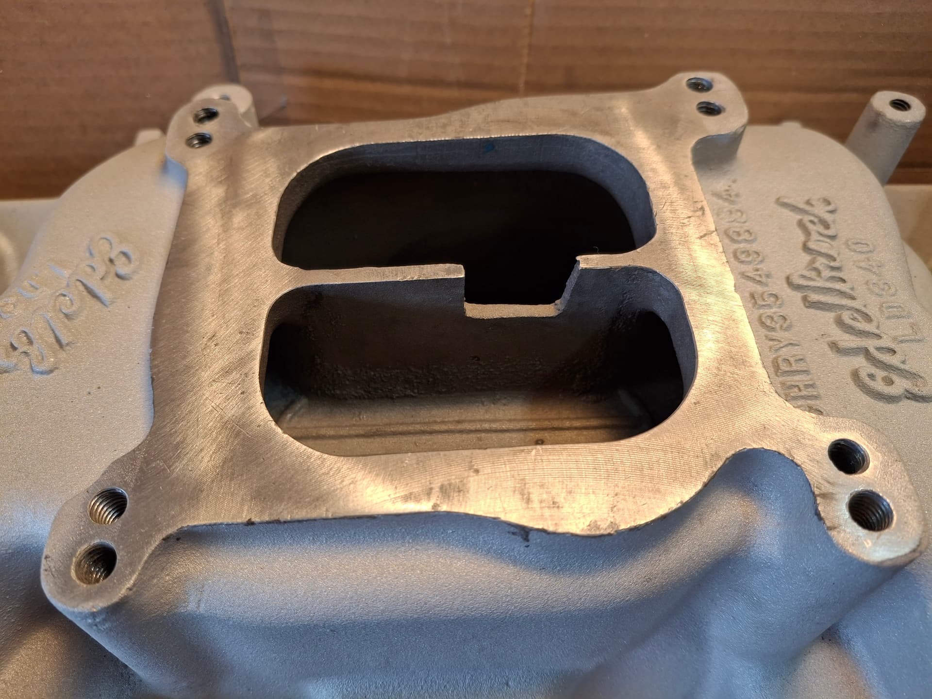
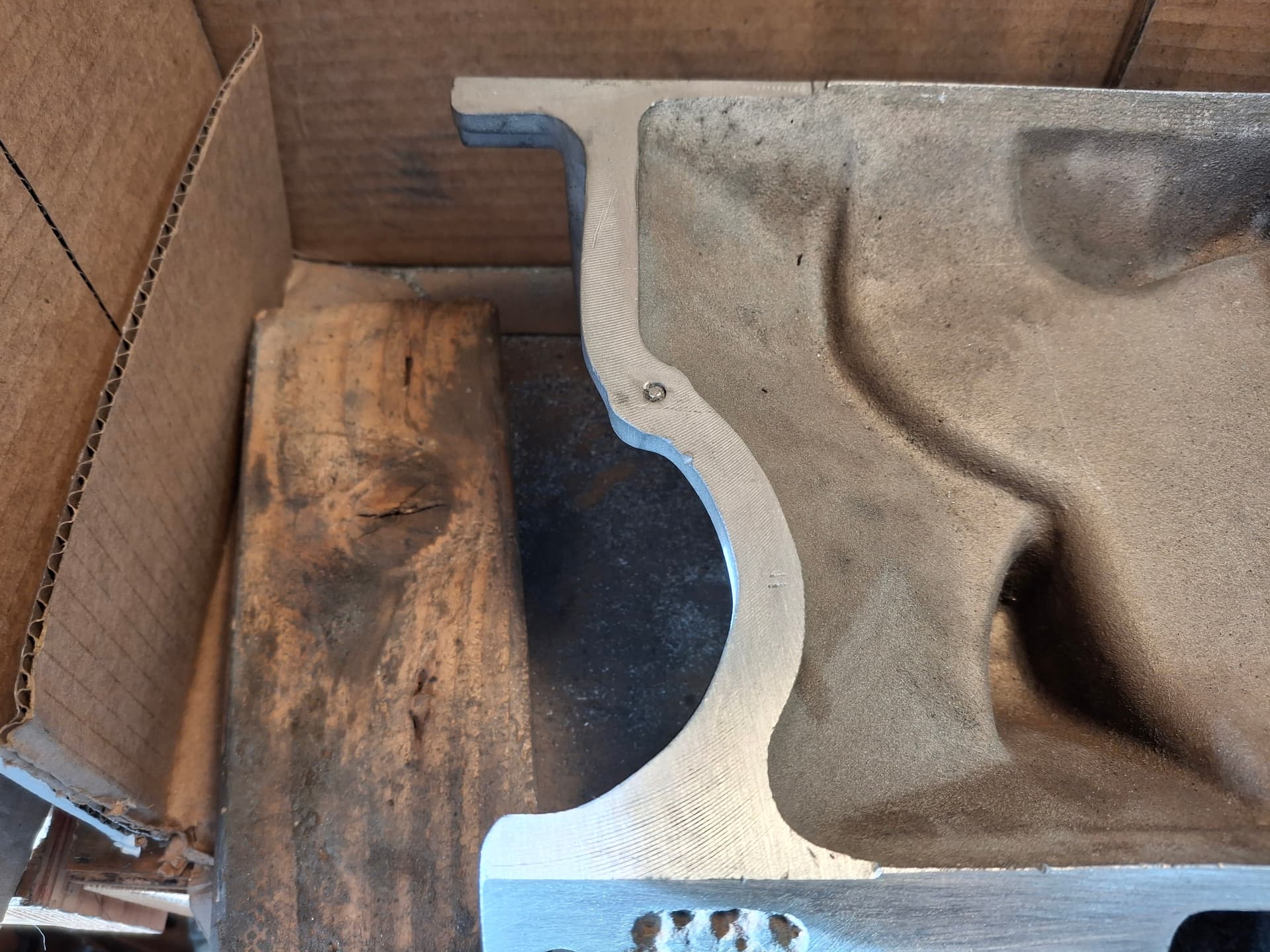
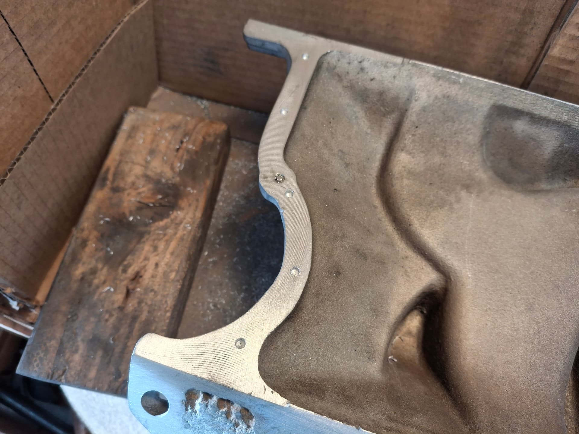
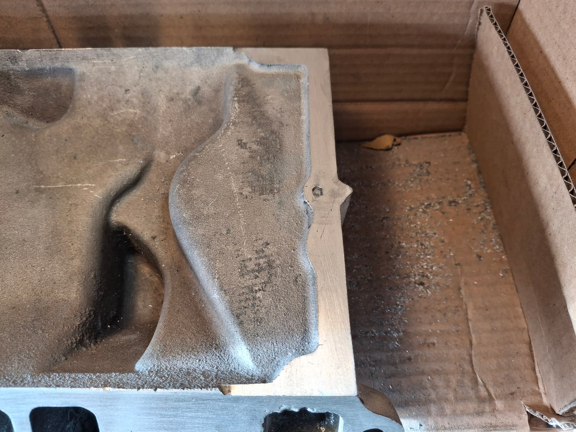
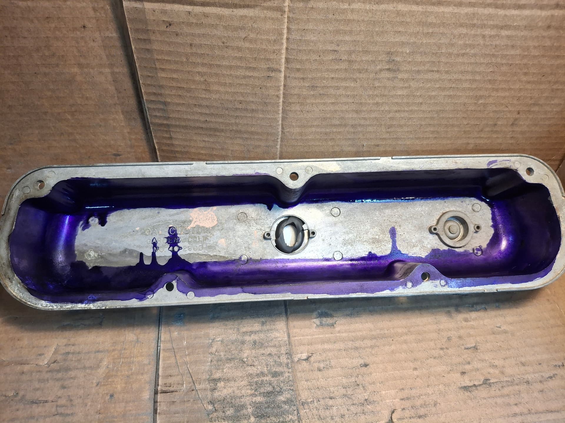
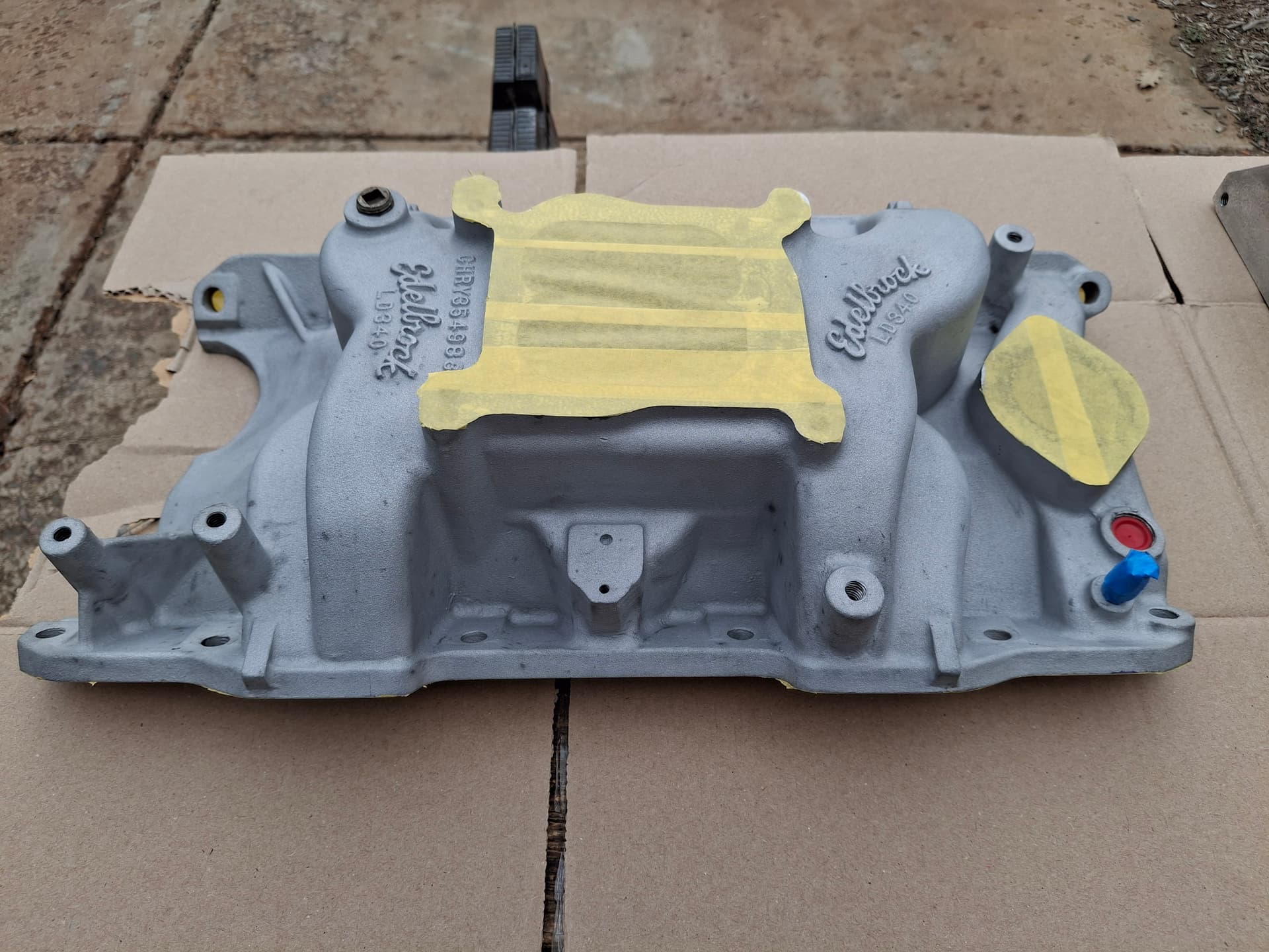
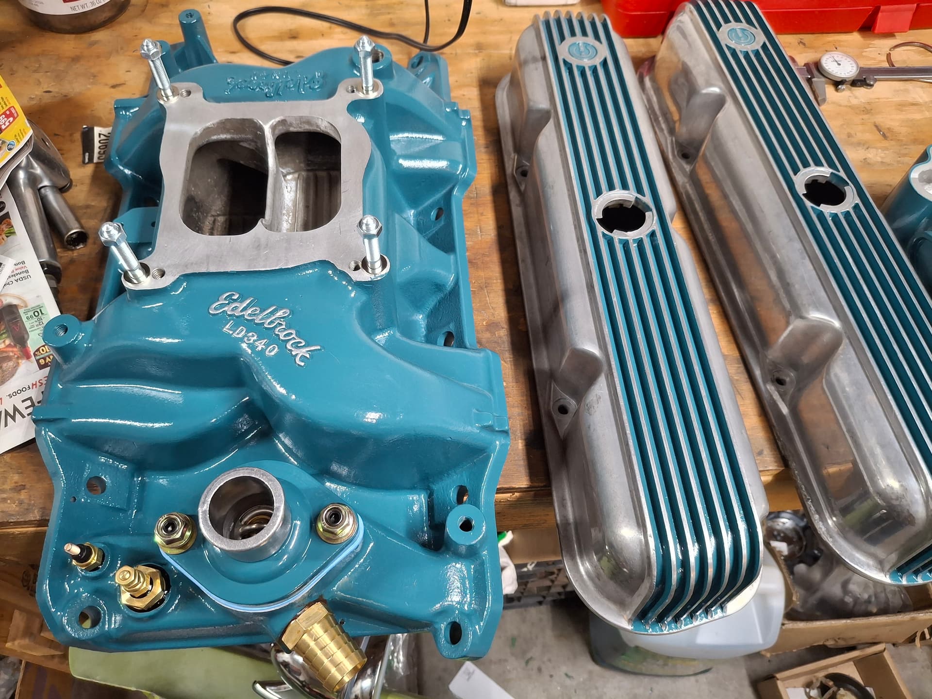
Before I could start on the matching the intake manifold’s ports, I addressed the plenum by smoothing out all the casting flash I could reach. From the factory, Edelbrock placed a crudely cast notch in the plenum divider to help promote a more-even mixture between both the planes. For this intake, a known benefit to allowing cylinders to draw from all four carburetor barrels is to widen the notch, and I went further by smoothing the top edge into a knife to stop the turbulence that would have been created by a flat top.

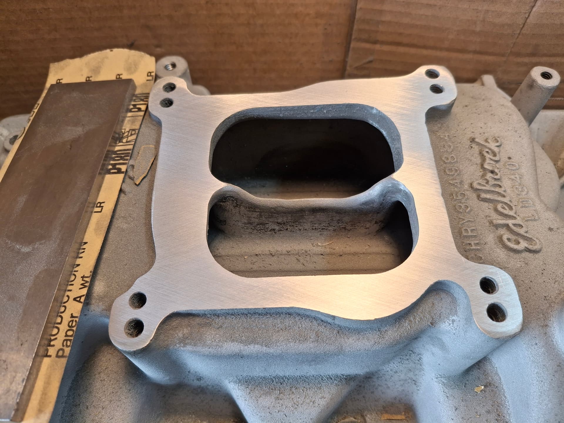
I needed to address the years of abuse people inflicted on the poor gasket flanges. Some nimrod(s) at one point(s) took a sanding disc to the carburetor and intake gasket flanges, leaving uneven surfaces with deep sanding grooves. This is a moment where a mill or surfacing machine would come in handy, but I settled for a machinist’s straightedge as a sanding block and a series of 80, 120, and 180-grit sandpaper. Working methodically to keep the block flat and in an “X” pattern, I wore out my arms bringing the flanges back to life.

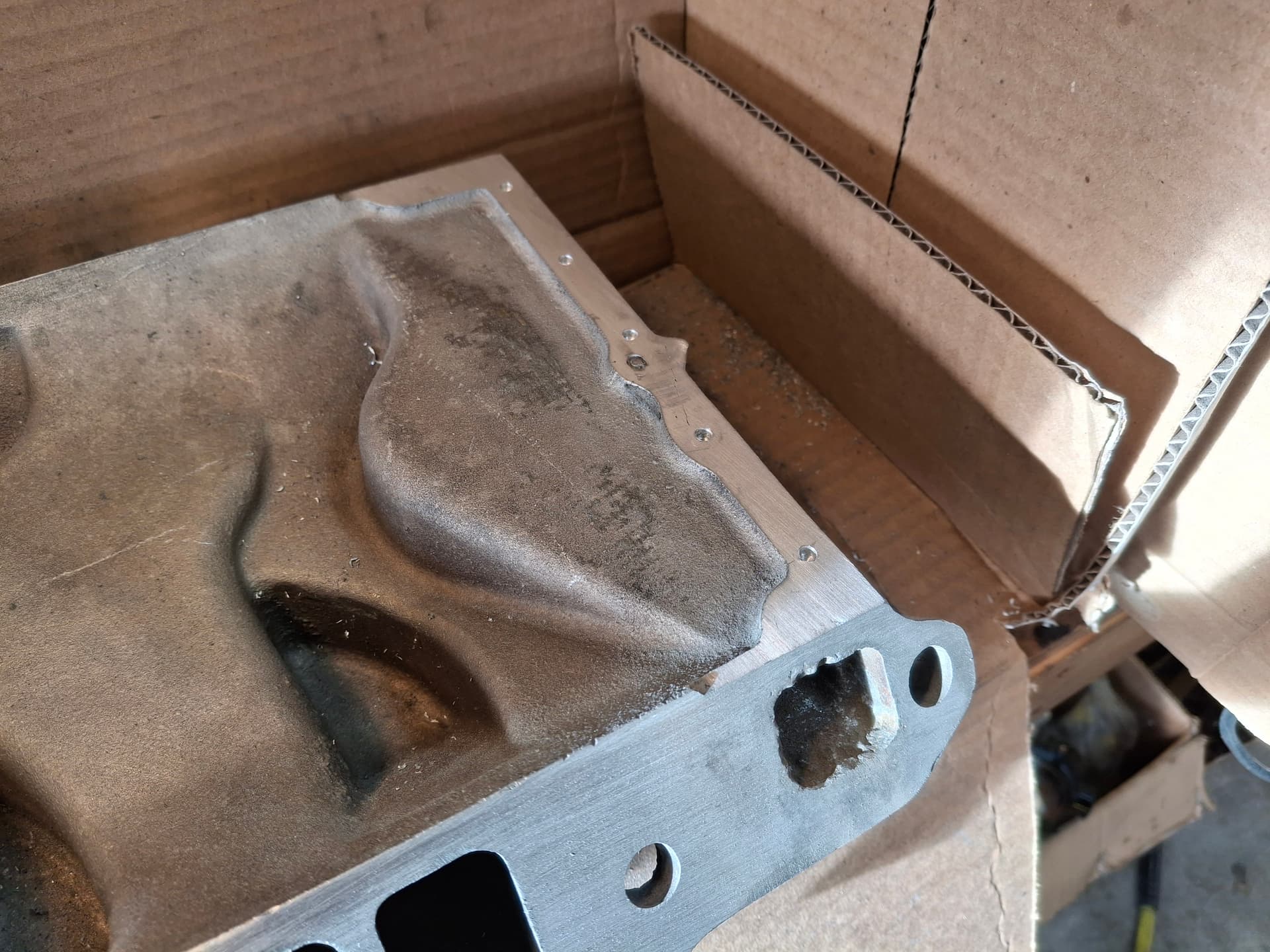
For the manifold end rails, I intend on using a bead of RTV silicone instead of the OEM cork gaskets. The block already has a series of holes drilled in the end rail, and I drilled a series of holes in the manifold end rails where the RTV will create teeth to help hold the gasket from blowing out.

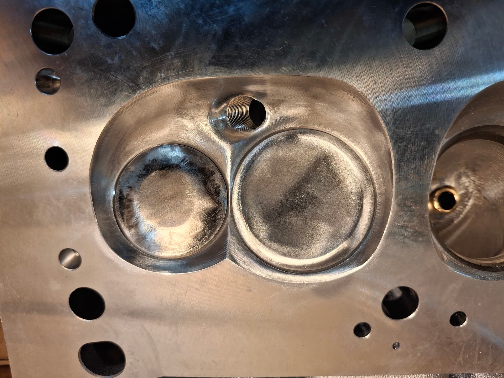
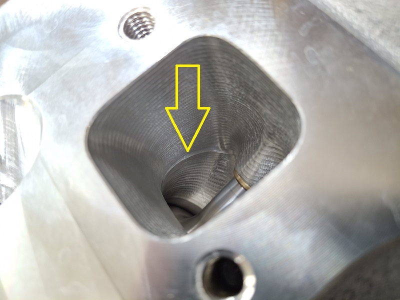
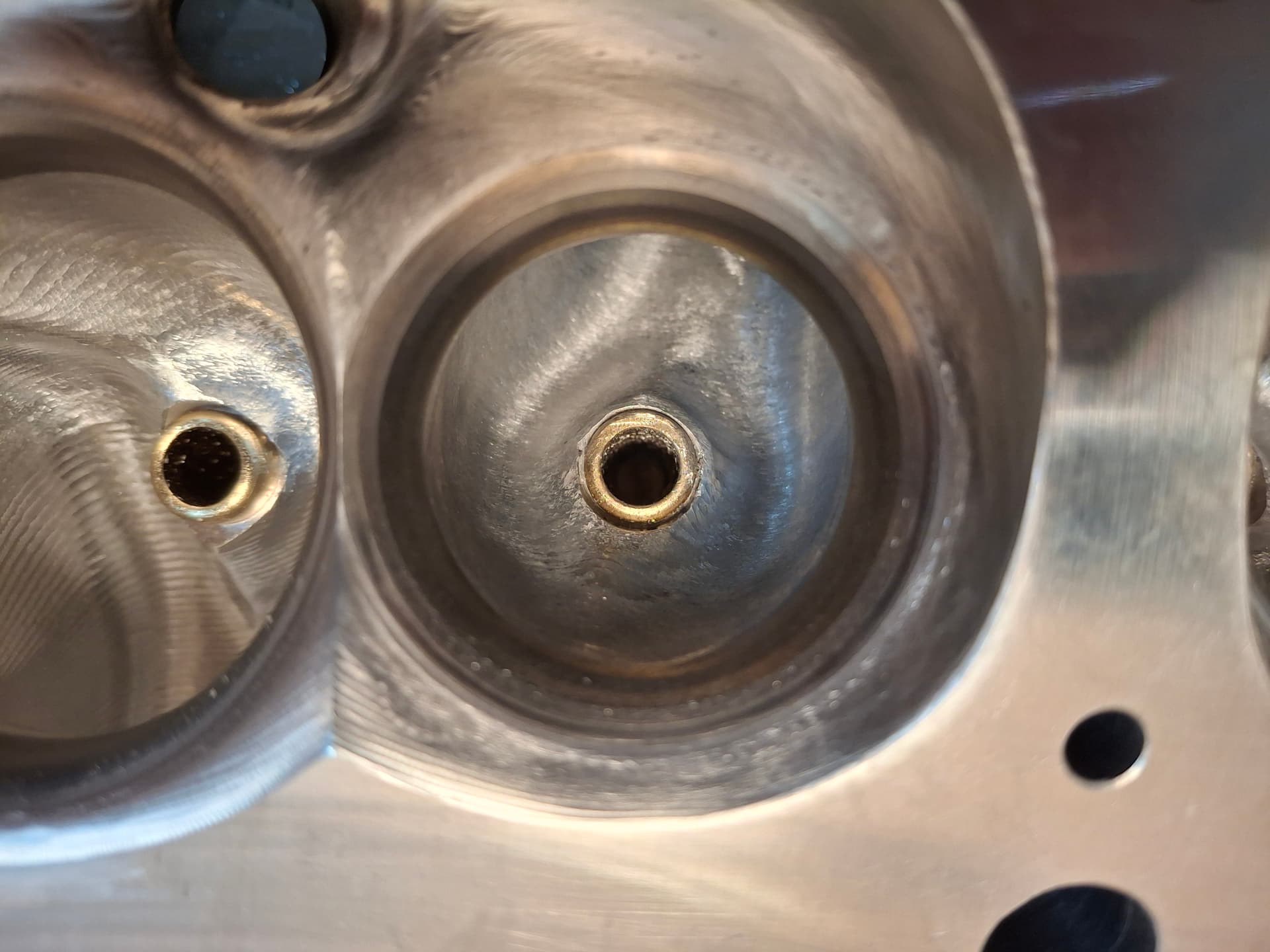
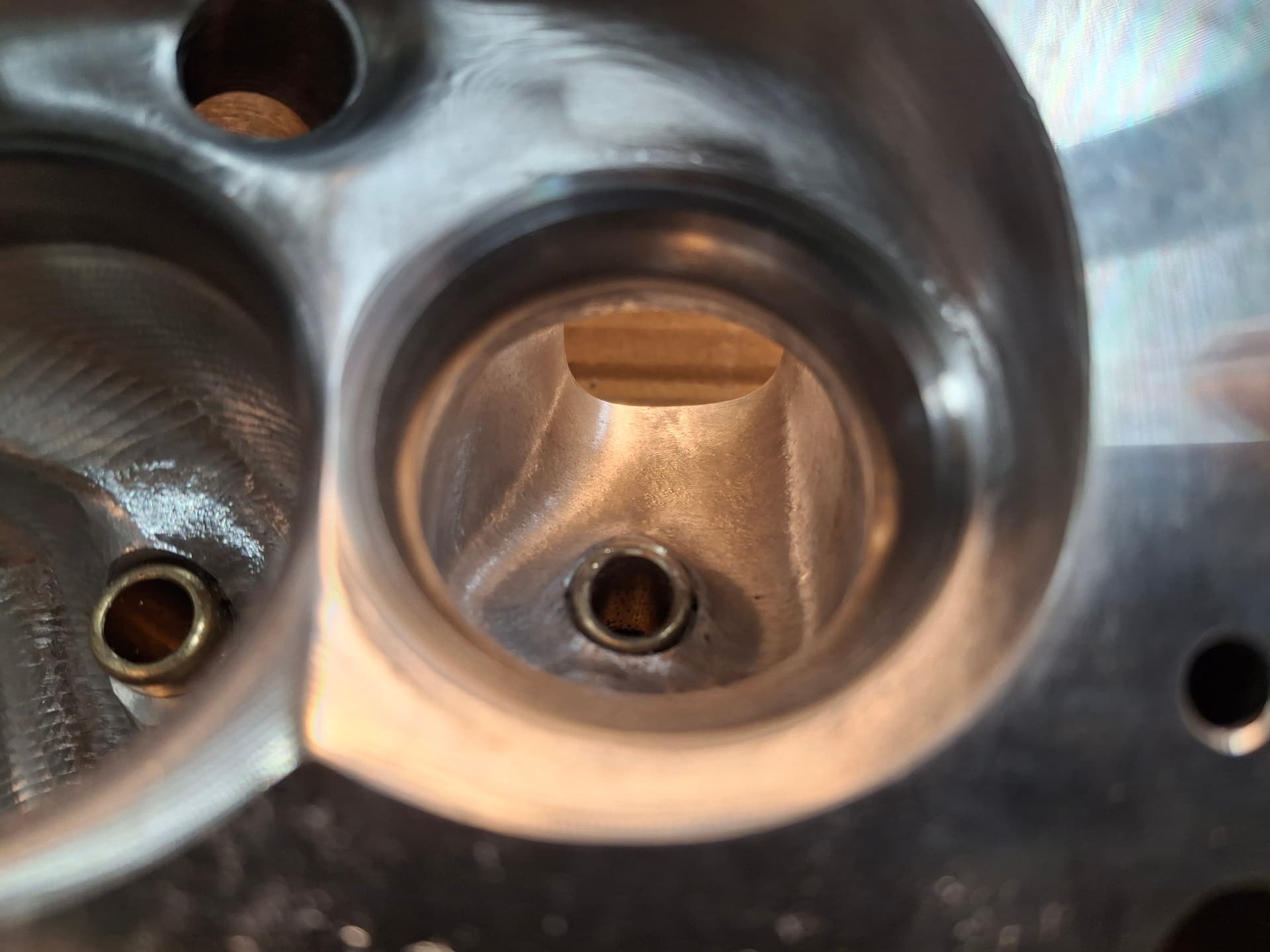
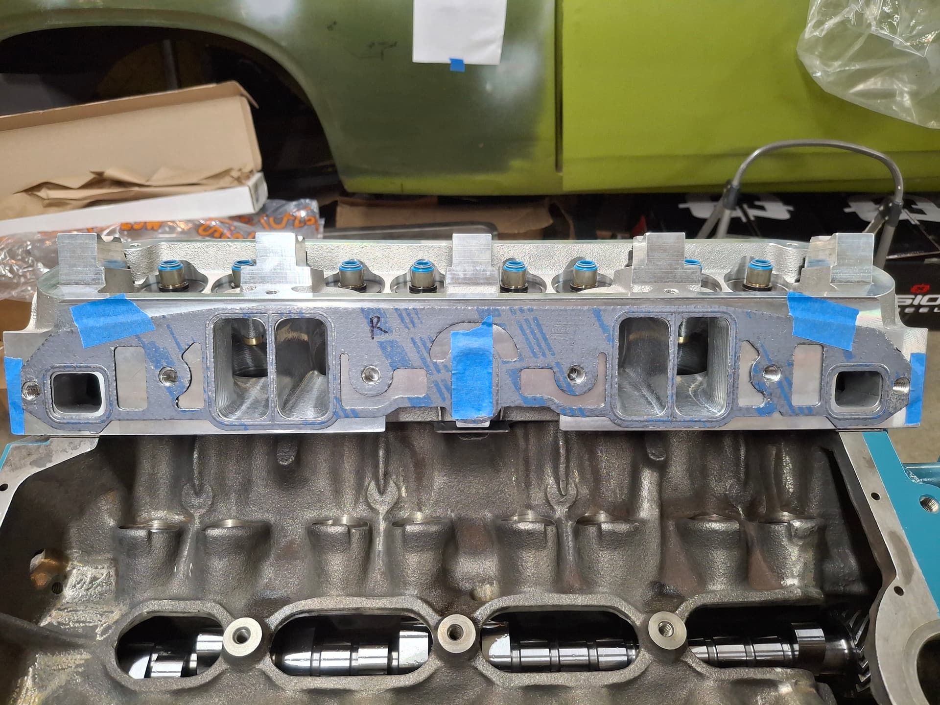
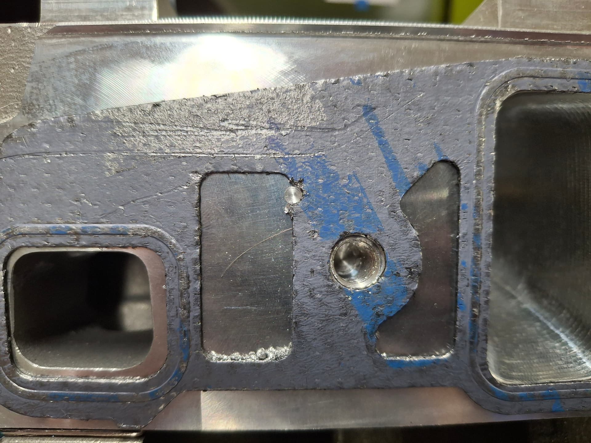
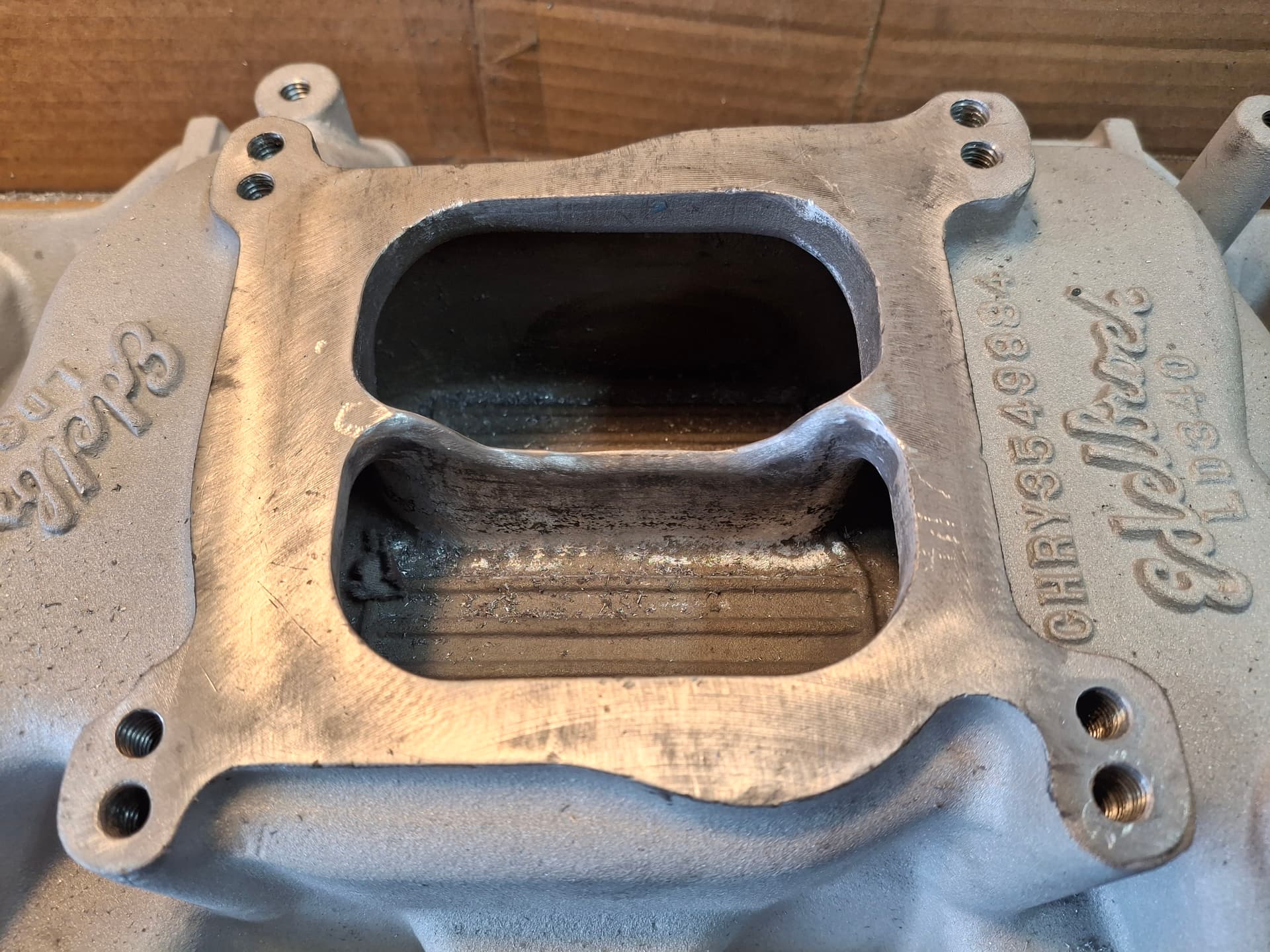
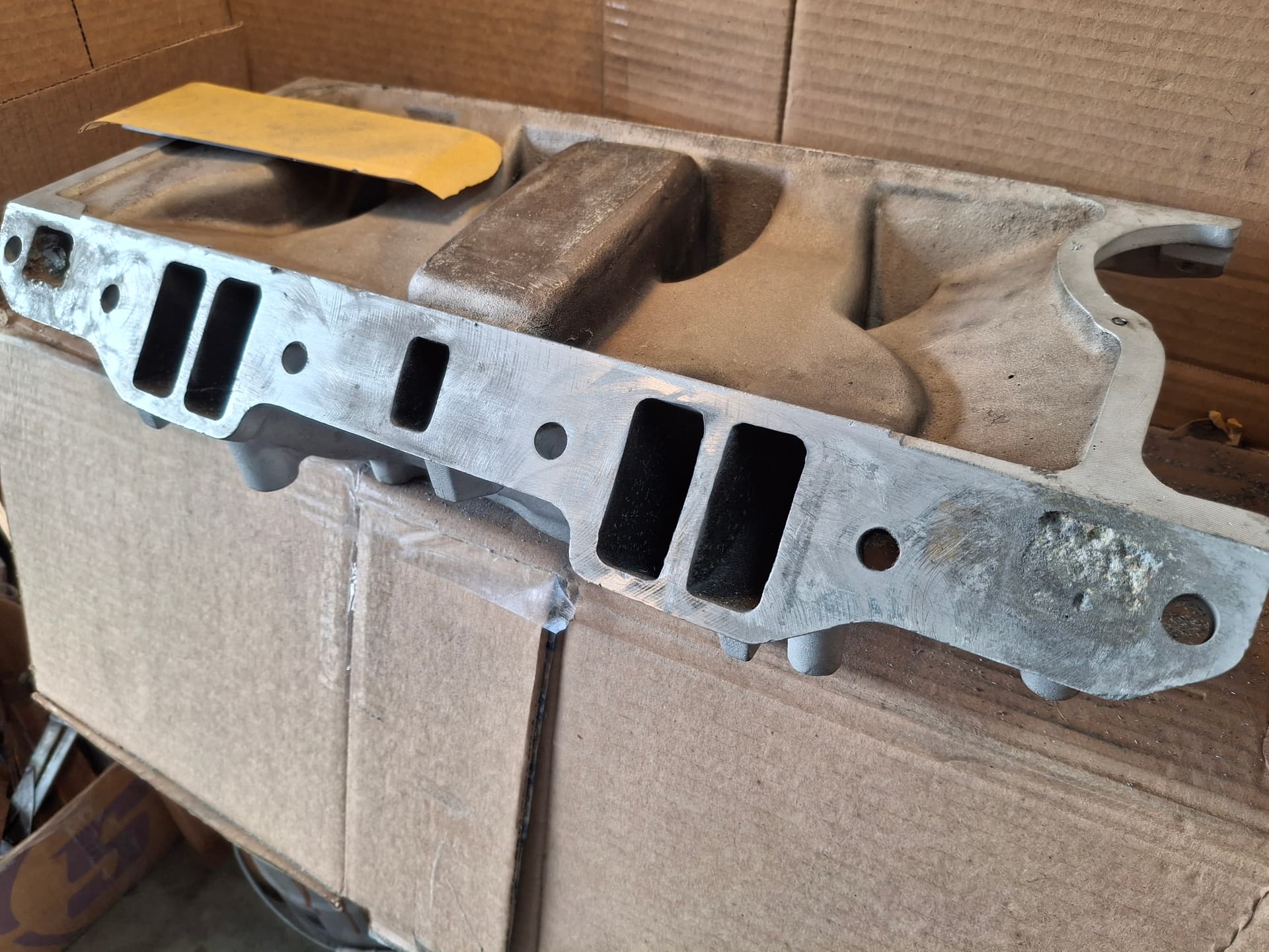
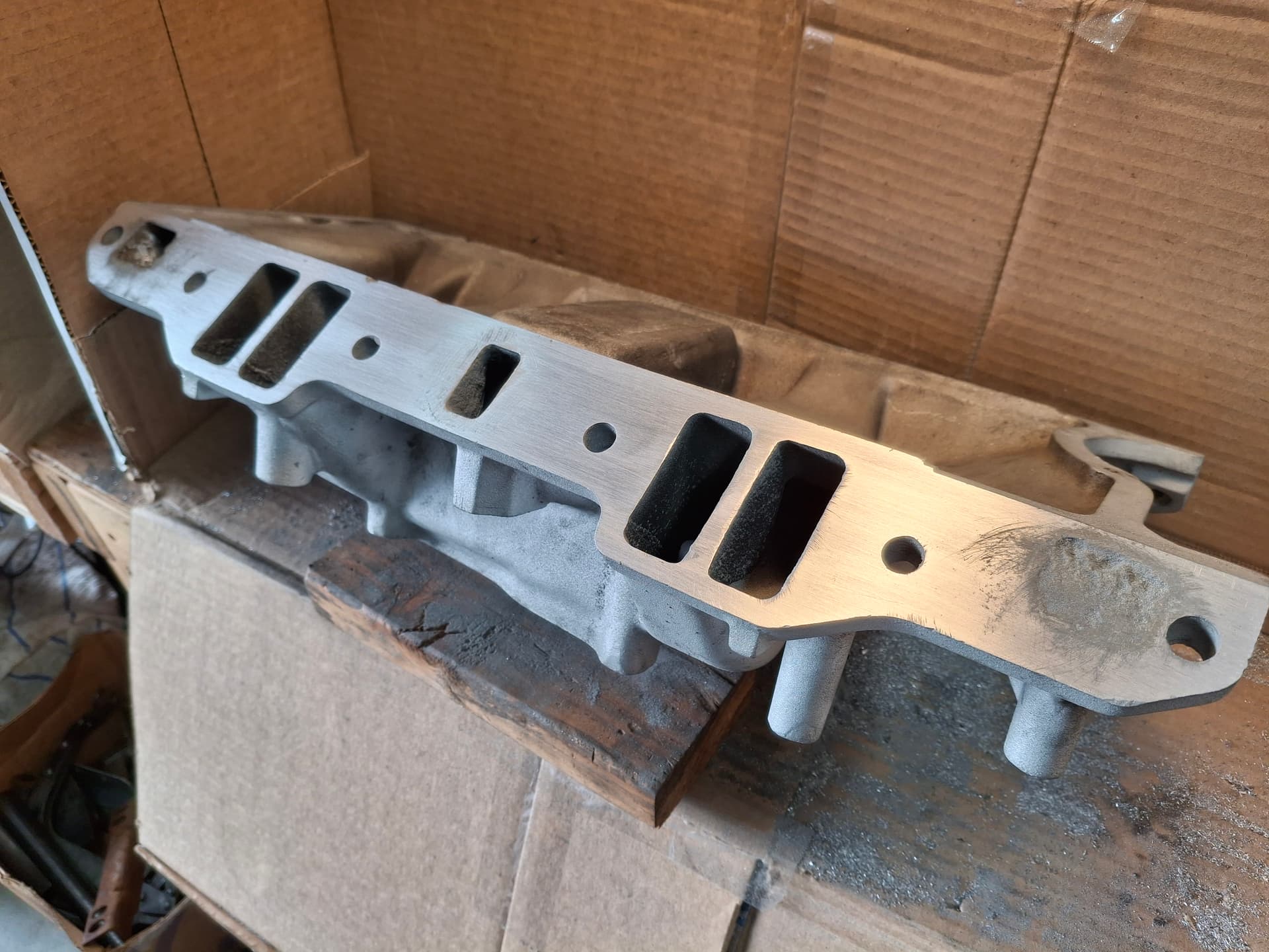
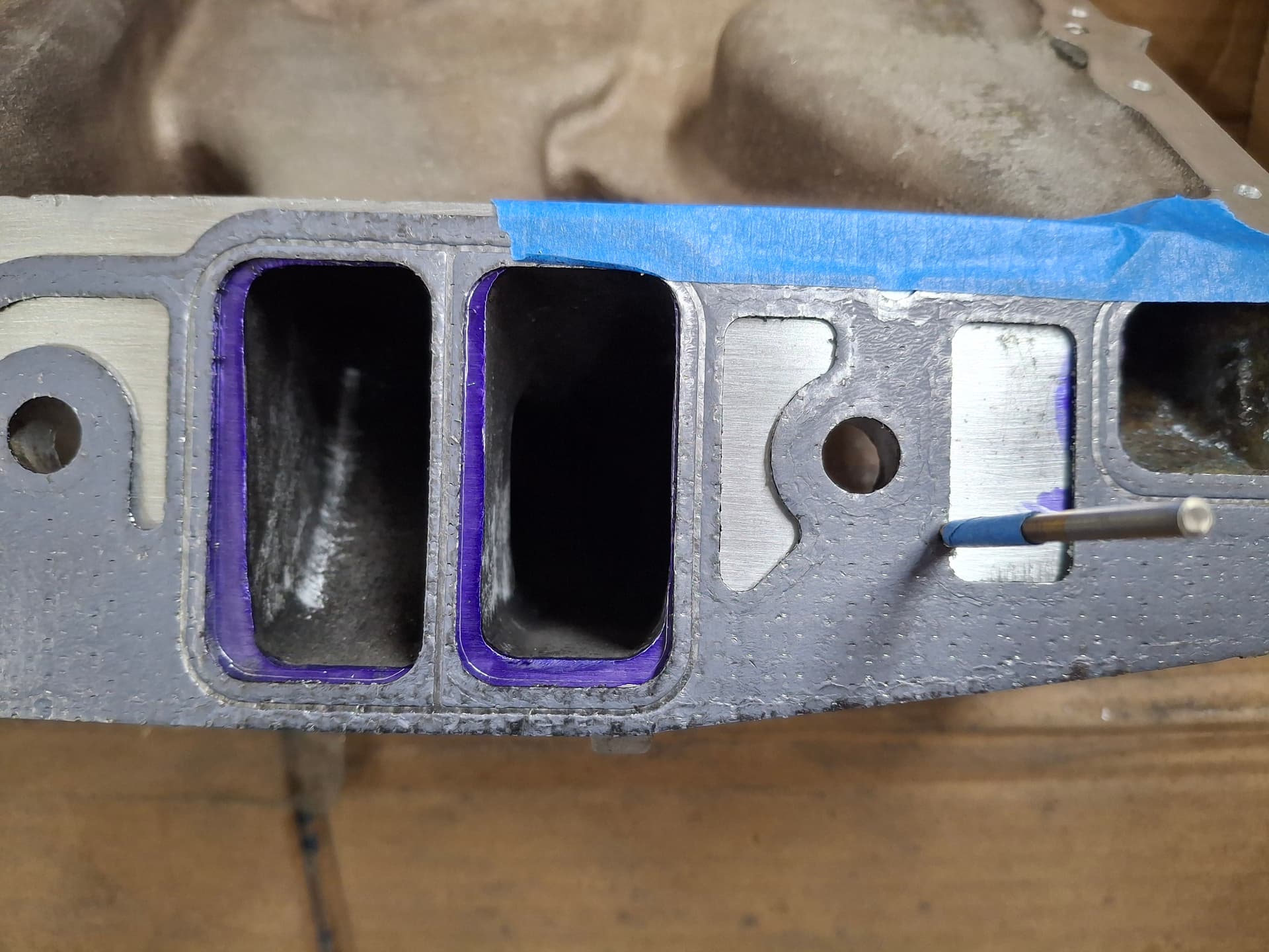
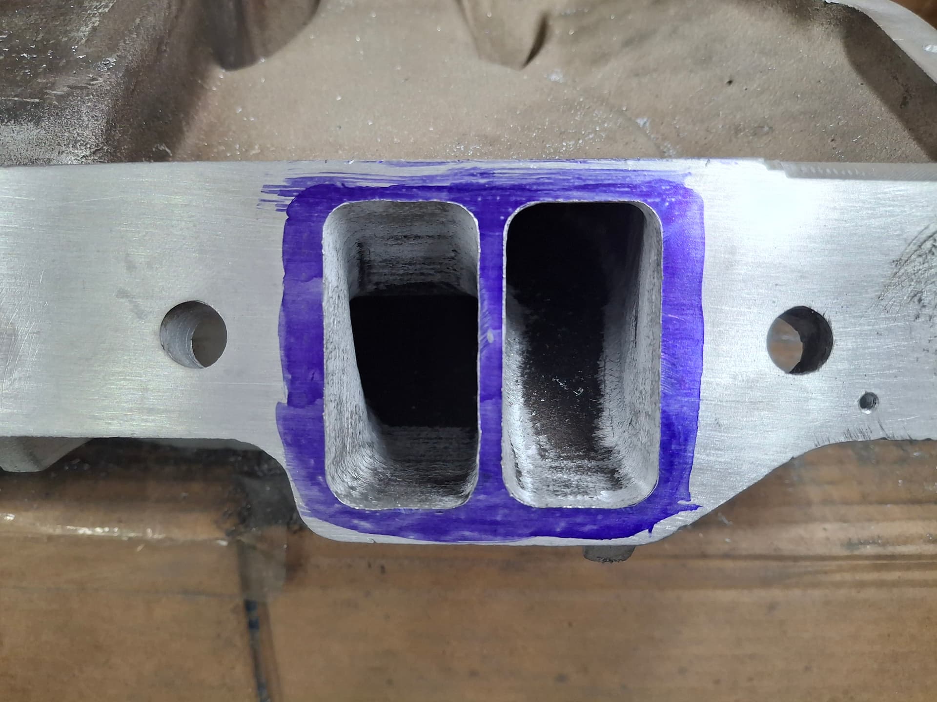
I was now ready to place the gasket on the intake manifold and index it using the 1/8" drill bits through the indexing holes before scribing the lines. As you can see from the photos, the factory intake ports not only are far smaller than the gasket and cylinder head ports, but they are also not symmetrical in the slightest. Shame on 1969 Edelbrock for such shoddy casting :grin:

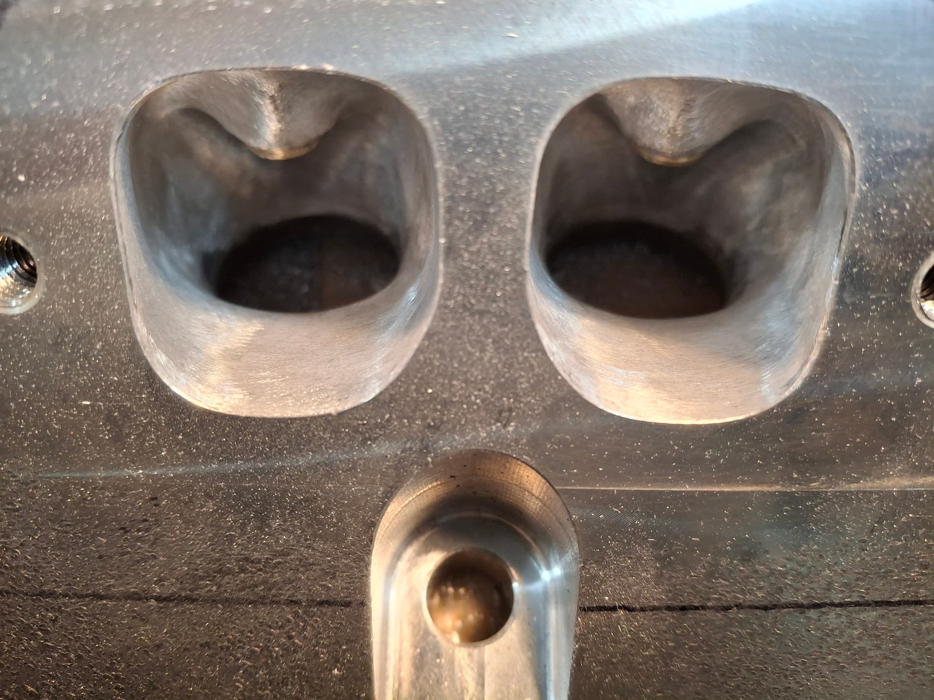
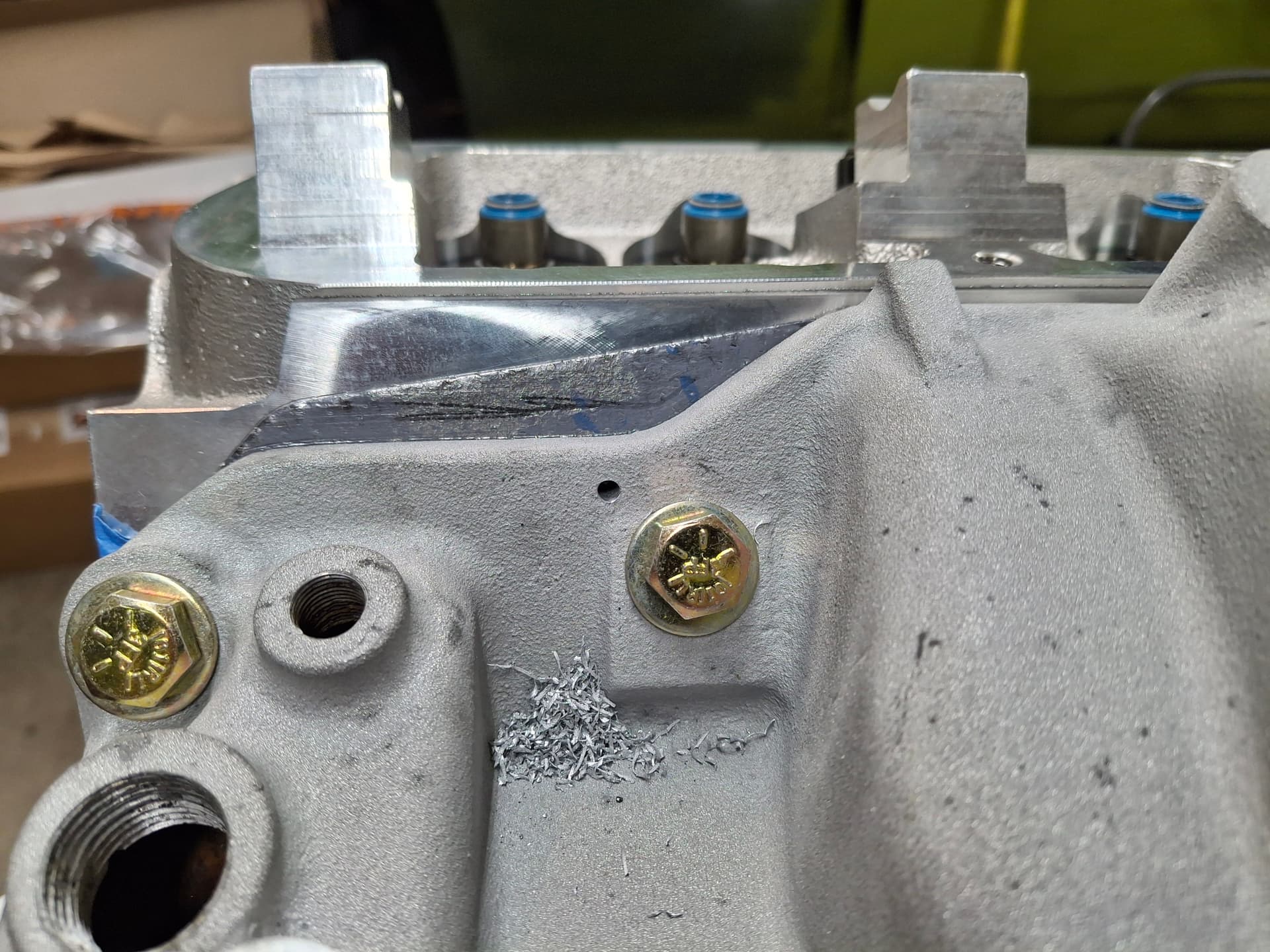
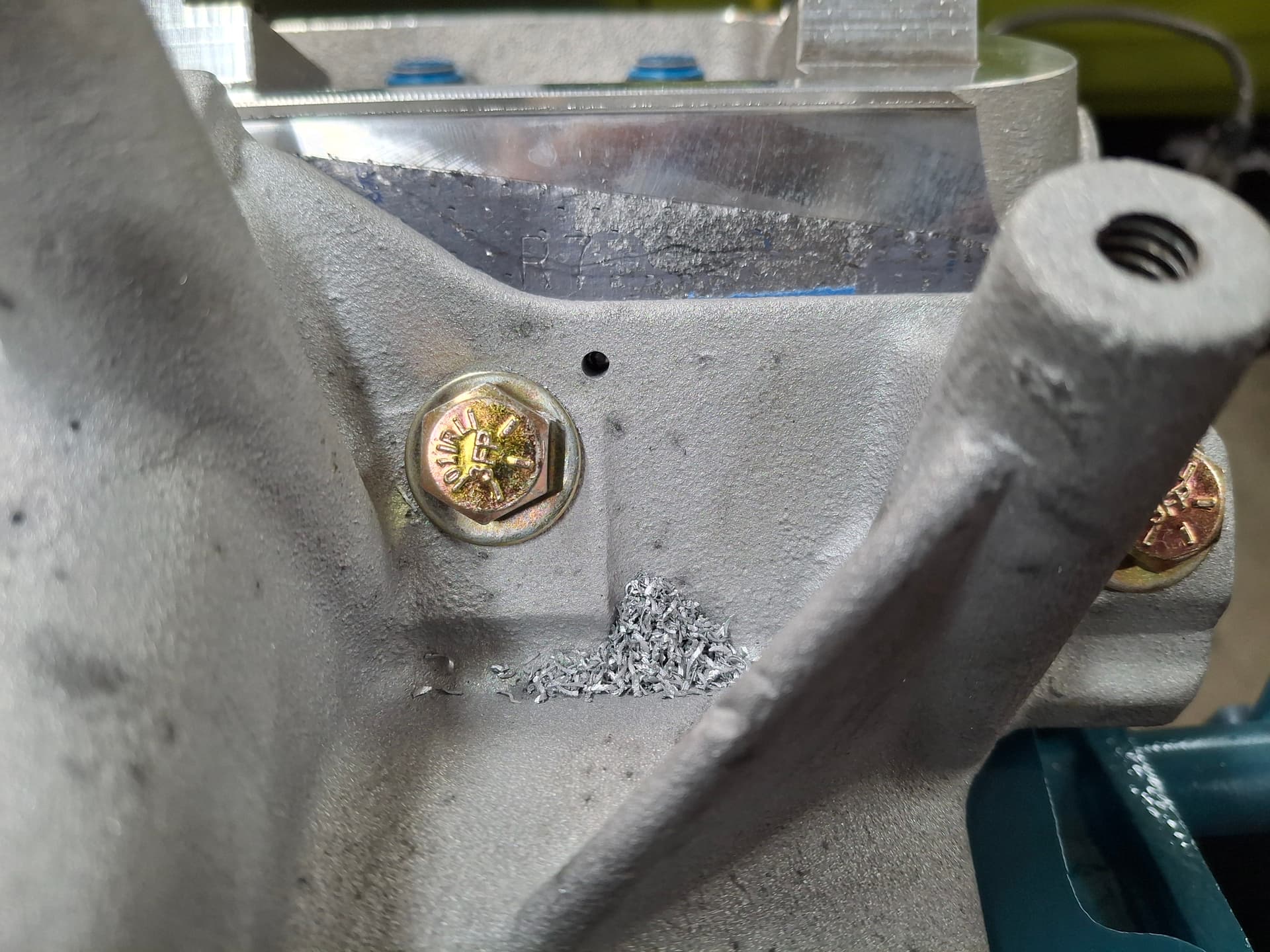
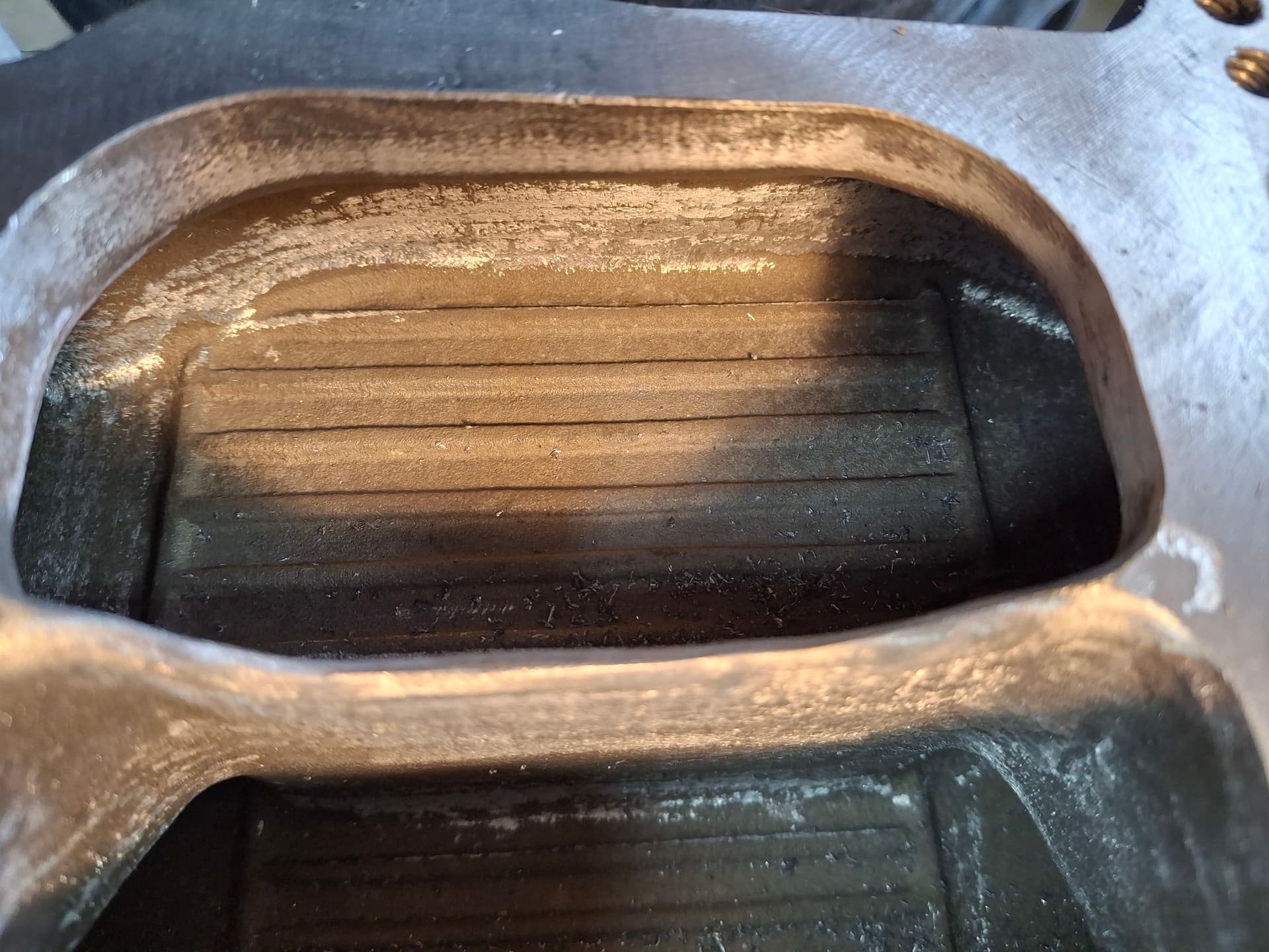
I went to town on the intake runners porting as far back into the runner as I could reach, which was 6" in some cases, so that I removed the same amount of material all the way to the plenum versus just flaring the runners at the ports. I used my grandfather’s outside calipers he used in WWII to maintain enough outside wall and his inside calipers to maintain symmetrical runners as best the casting allowed. On some ports, I had to remove 1/4" tick of material. The final produce is an intake with exact port matches with runners that are far larger and far more symmetrical than the factory casting. By the end, I had a pile of aluminum that would have filled at least one measuring cup and an air compressor as hot as a furnace even after letting it rest periodically.

Post Alert:
@jonUU
@Sportsracer
@Datsun78
@Bob_Alder
@Rich
@Nick_H

Front K Member
Before I paint the oil pan, I wanted to fit it in the car. I pulled the original engine and swapped the oil pan. As I suspected, when reinstalling the engine, the rounded corners of the K member would not allow the engine and transmission to drop in as a unit, so I needed to modify the K member or suffer the pain of having to pull the oil pan whenever I want to pull the engine and install the pan after the engine is installed. I first squared off the K member and prepped the rusty/greasy metal for welding. I slide a length of 2" x 3" x 3/16" wall tubing into the hollow K member, welded it in place, and gusseted the backside with a piece of 1/8" angle to tie the original K member bottom flange into the new tubing. I then boxed the sides with 1/8" plate. While the 3/16" wall tubing may seem overkill, what I found when removing the engine is that, even with the front cage tubes and the additional crossmember underneath the radiator, the top of the shock towers would bow in 1/8" with the engine installed and relax/bow out 1/8" with the engine removed without my Monte Carlo upper crossmember installed. After my modification, the shock towers do not move when the engine is installed or removed, so my redesign provides both more clearance and more rigidity than the factory K member. Coupled with the Monte Carlo upper crossmember, the front should be good to go on stiffness.

Cylinder Head Push Rod Clearancing

As has been the story of this project, what a manufacturer claims to be true is false. The cylinder heads are proudly advertised as being designed to accept 3/8" diameter push rods compared to the factory 5/16", which is bogus. My 3/8" x 7.630" x 0.082" wall chromoly push rods came in from Smith Brothers. After mocking up rocker arms, I found that the push rods contacted the bottom of the push-rod channel in the head at 0.100" lift, contacted the top of the channel at 0.550" lift, and started to bind at 0.620" lift (the cam’s maximum lift is 0.640"). I was frustrated having just fully cleaned and assembled the heads, so I had to mask the springs well to protect them from shavings and use a die grinder and an outside caliper to take off 0.050" from the walls of all sixteen push-rod channels to provide adequate hot clearance.

Valve Cover Clearancing

The factory stamped steel valve covers will not clear the cam lift and roller rocker arms without 1" tall extension plates, so I searched far and wide for many months until I found a nice set of reasonably priced late 1960’s Cal Custom finned aluminum valve covers. Even with their taller, squared-off sides, I was doubtful that they would clear the push rods or rocker arms. I applied Dykem blue to the inside of the valve cover, placed some Play-Doh balls atop the rocker-arm adjusters, bolted on the covers, and ran the valves through a couple cycles. To my pleasant surprise, nothing contacted the valve covers, and the Play-Doh showed 1/4" of clearance. The two areas I’ll have to check during final assembly are the portions of the valve covers that protrude down around the center hole and the optional knock-out since they may hit the rocker arm adjusters. If they do, I’ll knock them down with the die grinder.

Post Alert:
@jonUU
@Sportsracer
@Datsun78
@Bob_Alder
@Rich
@Nick_H

Engine Component Paint and Fittings
With the porting work on the intake manifold and cylinder heads completed, and with the valve cover clearance confirmed, I prepped and painted the components and thermostat housing with primer and Chrysler Green engine enamel. After scrounging some deals on studs and free-spinning nuts, I installed studs in the intake for the carburetor and thermostat housing and in the heads for the valve covers. I also installed the new high-flow 180° thermostat, coolant temp warning light sending unit, coolant temp gauge sending unit, and the thermostat bypass nipple.

Post Alert:
@jonUU
@Sportsracer
@Datsun78
@Bob_Alder
@Rich
@Nick_H

Rear Block Plugs
Another enjoyable weekend of work, joined by @Nick_H, we got the short block off the stand to install the rear plugs and mock up the clutch. The camshaft and coolant passages received expansion plugs, and the oil passages, including the second, hidden interior lifter gallery port, received pipe plugs.

Clutch FUBAR
The new parts issues continue. When I chose the clutch, I went with a USA McLeod unit one step down from a full-blown (read $2,000) sintered-iron race clutch with some serious spring pressure for both initial budget and future budget due to wear on the flywheel, although it may be a future upgrade. I expected the clutch to be high quality, but that dream has been shattered.

I’m using a hydraulic throw-out bearing that I have yet to order because I needed to mock up the scattershield block plate, flywheel, pressure plate, and scattershield bellhousing in order to mike the void to figure out what length throw-out bearing and shims I need.

Everything went together as expected until we got to the pressure plate. Three of the bolts aligned with the flywheel at first, but the fourth we misaligned. We rotated the pressure plate until we got five of the six bolts to align. The sixth hole, however, was misaligned because that mounting tab was bent down and in about 1/8". The bent tab also keeps the pressure plate off the flywheel at a slant by about 1/16". There is no evidence on the cardboard box and pressure-plate paint that this is post-production damage from a drop, so it was during manufacturing. The most worrisome part of this issue is that I have no faith McLeod actually neutral-balances the pressure plate assembly prior to packaging because this pressure plate would not have bolted up or sat flat against their balancing mounting plate. I’ll definitely be having the flywheel and pressure plate balanced as an assembly.

We were still able to bolt on the scattershield, measure the void (taking into account the bent plate), and measure the transmission to calculate the throw-out bearing and shim lengths needed, and I have a replacement clutch on its way.

Post Alert:
@jonUU
@Sportsracer
@Datsun78
@Bob_Alder
@Rich
@Nick_H

Steering Box
I swapped out the factory 24:1 ratio steering box for a new aluminum 16:1 box that was used on the Formula S Barracudas. The box received a new pitman arm as well.

Idler Arm
The factory idler arm uses rubber bushings at the chassis attachment point, which creates excessive flexing since the rubber gives before the arm rotates. I replaced the factory idler arm with a custom unit that uses a steel bushing and Torrington bearings from Bergman Auto Craft, which should tighten up the steering. I’m leaving off the steering linkage until after installing the engine to make things easier.

Front Suspension
I disassembled the front suspension for final installation. I finished the welds on the lower control arm sway bar brackets, primed, and painted the arms chassis black. After lubricating all the components and cutting the lower ball joint bolts to length, I assembled the front suspension and set the torsion bar preload for the baseline I noted during mock-up, which I’ll double check when the car is completely assembled before setting front alignment. I’ll also need to do the final adjustment on the upper control arm for caster/camber and lower control arm strut rods with the car at ride height. I installed the shocks.

Front Brakes
I packed the front wheel bearings, installed the grease seals, installed the rotors, and cleaned them well. I drilled the caliper bracket bolts and the caliper bolts for safety wire. A bit broke off deep in one of the mounting bracket bolts that ended up taking me an hour to extract, but what’s new with drilling safety wire holes through alloy bolts? I installed the new racing brake pads and dialed in the caliper center with shims before doing final assembly. Since the braided stainless brake hoses get close to the lower control arm during full turn but don’t rub, I split lengths of 3/8" fuel hose and tied them around the hoses as precautionary additional sheathing. I installed the NPT-to-AN fittings in the calipers, installed the hoses, and tightened the inverted-flare nuts.

Post Alert:
@jonUU
@Sportsracer
@Datsun78
@Bob_Alder
@Rich
@Nick_H

2 Likes

Completed Brakes
The punches keep rolling with the USA-made quality control issues. The irony is that I haven’t run into nearly as many quality control issues with imported parts. My Motul 600 brake fluid came in, and I removed the three Wilwood master cylinders to bench bleed them. For mock-up, I just barely threaded on the 1/8" NPT adapter fittings by hand, so I removed them to apply TFE sealant paste. Upon inspection, I noticed some aluminum shavings in the first MC port I checked, so I removed the snap ring, piston, and spring for a better inspection. The spring was covered in shavings, and the inside bore had a lot of shaving too. This was one of the 1" brake MCs, so I checked the other 1" MC and found the same issue. It looks like Wilwood must have tapped the threads after final assembly for some stupid reason (likely an issue caught after assembly) and left all the shavings from my brake system to eat. The 3/4" MC for the clutch had no shavings in it, although I still disassembled it to check and clean it. I cleaned everything out, lubricated the parts, and reassembled them before bench bleeding. I’m thankful my perfectionism in inspecting everything paid off since these shavings would likely have destroyed the MC seals and could have made their way into the calipers and destroyed those seals too.

After handling the MC issues, I got the brake system and clutch system buttoned up and vacuum bled; we’ll pressure bleed the systems next time Nick Hill is over. I’m happy to report that the pedal travel looks like it will land where I was hoping (farther down toward the firewall), and the only leak I have found, so far, is two of the front caliper bleeders are weeping. I’ll pull those and see if there are any blemishes but might just need to snug them down a bit more.

Completed Fuel System
I pulled the fuel cell and the cell housing in order to finish some cutting and welding on the outer firewall box. Once that was finished, I bolted the fuel cell in place, tightened all the fittings, installed grommets and a separator clamp, and made/installed a ground wire from the aluminum filler plate to the car body. The fuel system is now complete from the tank up to the carburetor fuel rail. I’m going to leave off the aluminum firewall lid until I can pressurize the system and check for leaks.

Wheels and Tires!
My imitation 1960’s Halibrand Indy Car style wheels (15" x 8") came in a while ago, and my American Racer tires came in last week by way of RMVR’s Sterling Chase who is a distributor. I went down to RMVR’s Tom Penewell’s house in Monument who was kind enough to help me mount them using his swing-arm machine. When I got back home, I balanced them with my trusty 1960’s Coats M-60 Micro Precision bubble balancer. If you’re going vintage, you might as well go vintage balancer :joy: I think the wheels and tires look great, and clearances look good with some minor body adjustments. Now that I know the wheels work, I’m going to order a spare set. For the spare set, I’m going to try the next wider tire size on the rear since I still have 2" of clearance between the inside sidewall and leaf spring, but I’m limited in both tire selection and in that these wheels come only in 8" with zero offset when ideally I could get them in 8.5" with 1" positive offset.

Front Fender Clearancing
With the new wheels and tires installed and the car on the ground, I found that the fenders needed trimming to allow the wheels to turn inward. A 1" angled haircut took care of the issue with plenty of clearance for suspension movement once the engine is installed. When I do the bodywork, I’ll weld an inside lip on this cut area for rigidity and to match the existing 90° return to where it will look more factory.

Post Alert:
@jonUU
@Sportsracer
@Datsun78
@Bob_Alder
@Rich
@Nick_H
@jackson_prime101

1 Like

It’s a good thing you caught that now Justin. Your OCD is paying off!

1 Like

Windshield Safety Clips
While I await the new glass windshield, I welded in the threaded bosses for the safety clips and built the clips out of 1" wide x 3/16" thick aluminum strap. The GT-1 spec calls for two on the bottom and three on the top. Once I install the windshield, I will bend the straps over and down the rubber seal onto the glass for a tight fit.

Rear Window
The fastback rear window is massive and, while I haven’t weighed it, has to weigh at least 30 lbs. The one that was in the car was intact but badly, badly scratched. Reproductions are sometimes available at a hefty $800 after freight, or I might have been able to find a glass expert who could sand and polish out the deep scratches. To address both the weight and the need for a rear window, I decided to build one from 1/8" polycarbonate with double-sided abrasion resistant coating. After getting quotes from five different local distributors and national, I went with Plasticare in Englewood (thanks Tom @Sportsracer for that recommendation) who were the “cheapest” at $370 for a 4’ x 8’ sheet. I needed just under 5’, but, of course, a 4’ x 10’ sheet where I could have a window and a spare is special order and upwards of $800, so I ended up with enough for one window and a 3’ drop I’ll likely never use. While I was originally thinking of using 3/16" thick out of concern the wind buffering would be an issue with lighter gauge, my buddy Brian told me he uses 1/8" in his Barracuda with no issues of oil-canning/flapping around.

A huge thanks to Nick Hill @Nick_H who came over last Saturday and spent the day with me painstakingly scribing and nibbling away at the window with a saber saw and sander until we go it as perfect as I think anyone could. It turned out better than either of us expected, especially since it was our first time working with polycarbonate of this magnitude. I got to wreck my flesh and arms contorting myself in and out of the roll cage on the underside to scribe the plastic, drill holes, and hold the nylock nuts, and Nick got to wear out his arm and hand tightening some 40 screws multiple times from above as we fit and cut, fit and trimmed, fit and . . . .

For you old timers out there, do you remember Bob Riggle’s “Hemi Under Glass” drag car that had a 426 Hemi in the back seat? I’m not as glorious as a 426 Hemi, but there was a Justin under glass for most of the day, and I have the bruises to show it.

(Note the evidence of Nick in the background for those questioning if I’m making this stuff up)

Post Alert:
@jonUU
@Sportsracer
@Datsun78
@Bob_Alder
@Rich
@Nick_H
@jackson_prime101

1 Like

Justin
That rear “glass” came out fantastic! I may take the piece of drop off your hands if you don’t need it, I’d like to replace the rear glass in the Miata hard top. Of course I would have to ask for your help with the fitment and the install! It would be a winter project ( next winter), think about what you want for it. I need to measure the glass but I’ll get that done today as I have a little more prep to do before Albuquerque. emphasized text

1 Like