Justin, the car is starting to look beautiful!
1 Like
Hey Tom, If I don’t end up needing it for another project (I doubt I will), let’s talk about you buying it for sure, and I’d be happy to help with install if you need the second hand.
Thanks, Jackson. It was nice meeting you in person.
1 Like
Spoiler Alert! and Air Dams
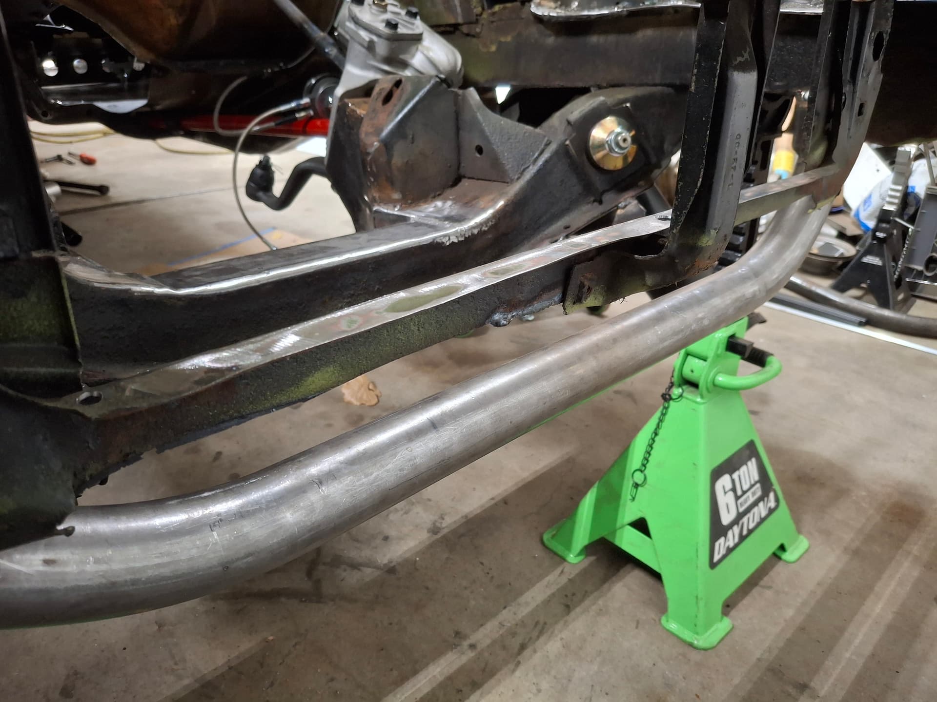
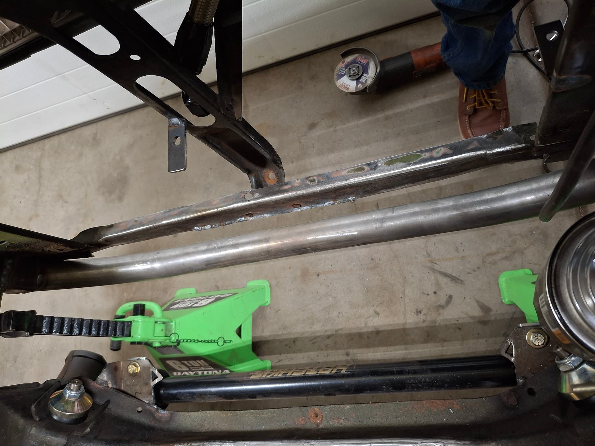
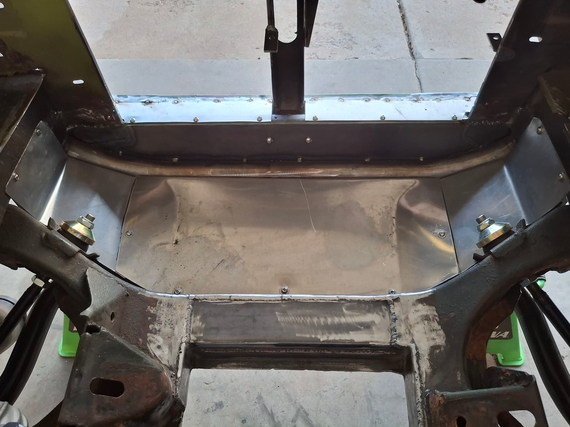
While aesthetically I’m not a fan of front spoilers or splitters, their function is pretty important to where I caved to it over form. The first thing I had to address was the badly rusted and flimsy lower panel of the radiator core support to originally tied together the front subframe and held the vertical grille support. Rather than trying to work with the mangled piece, I cut it out completely and broke up a 16-gauge steel panel to replace it. Doing so allowed me to weld that panel to both the core support and the entire length of the new tube crossmember I fabricated, which further stiffened the subframe and suspension.
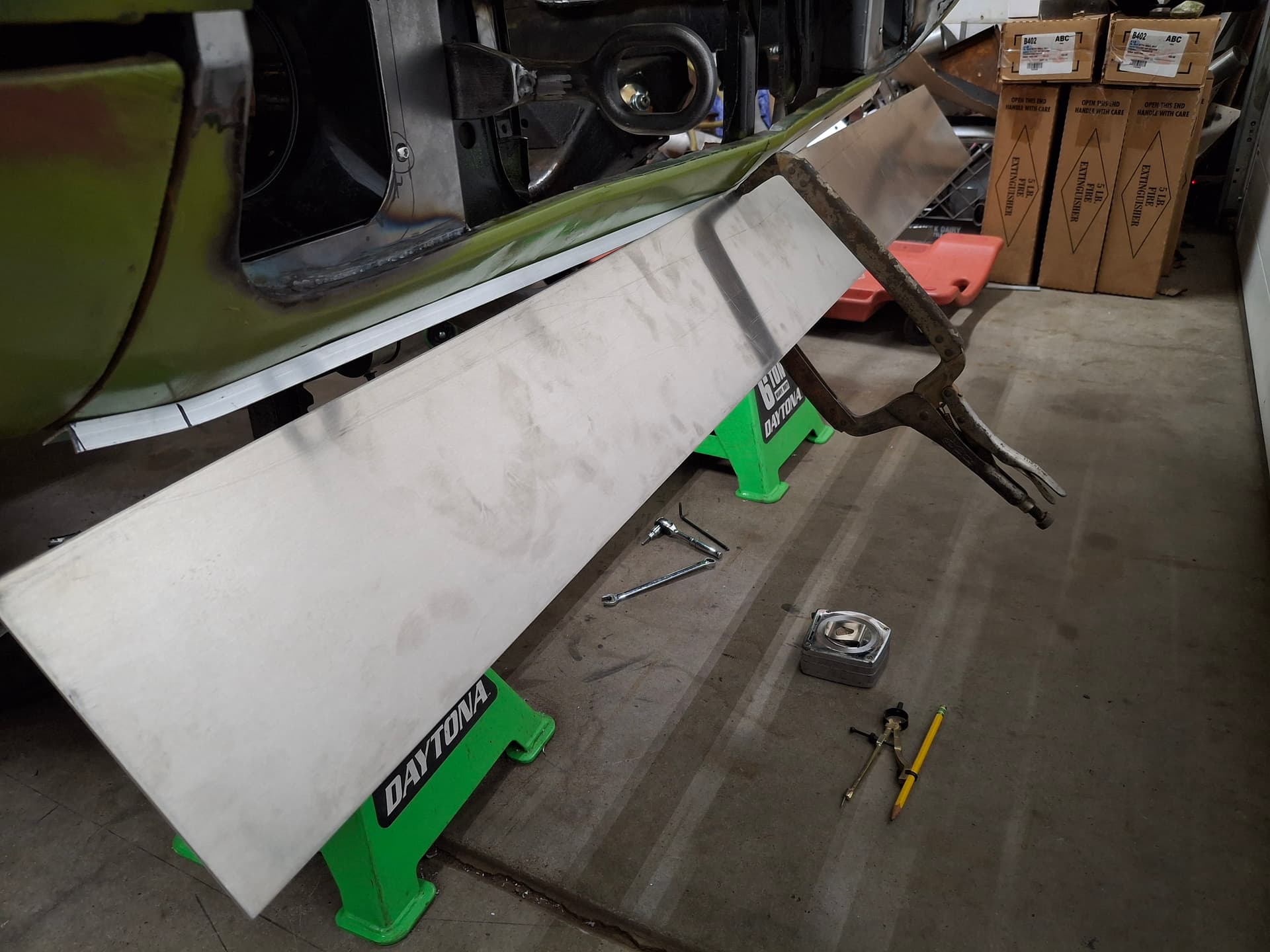
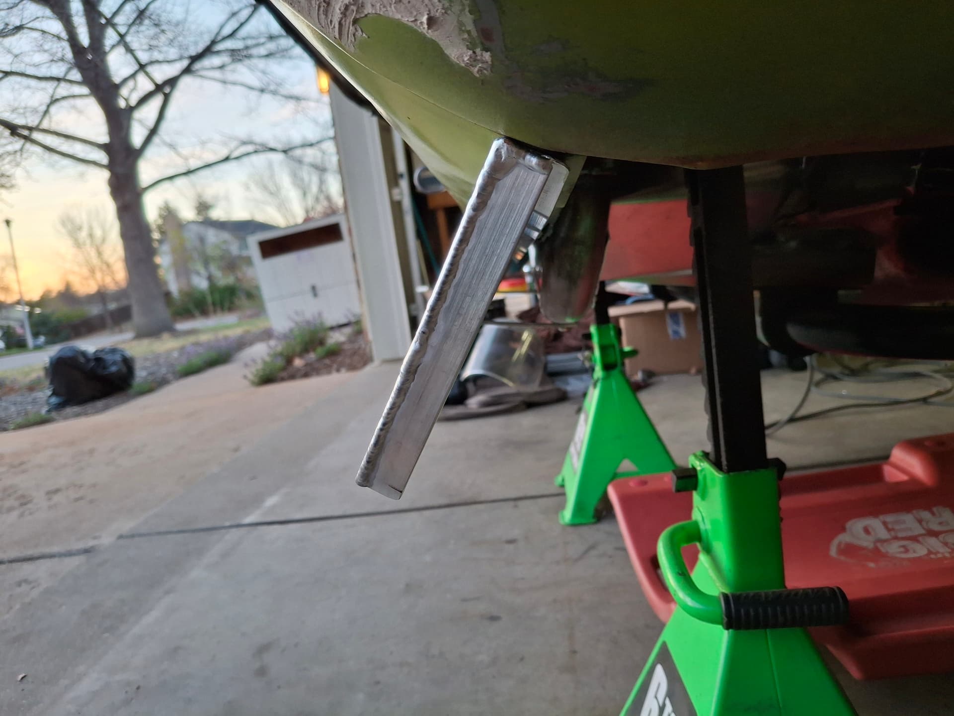
I turned my attention to the spoiler, which I fabricated out of aluminum angle for the mounting surface and .090" aluminum sheet. I first took some measurements with the car on its wheels to get an idea of the spoiler’s height. After bending the angle to the valance contour, I drilled the #10 mounting screw holes and secured it to the valance. I clamped the aluminum sheet evenly, squared it level with the bodywork, and used a compass to scribe the sheet to the valance before cutting it. Once I dialed in the fit with a disc sander and hand files, I TIG welded the angle to the sheet along its entirety for rigidity.
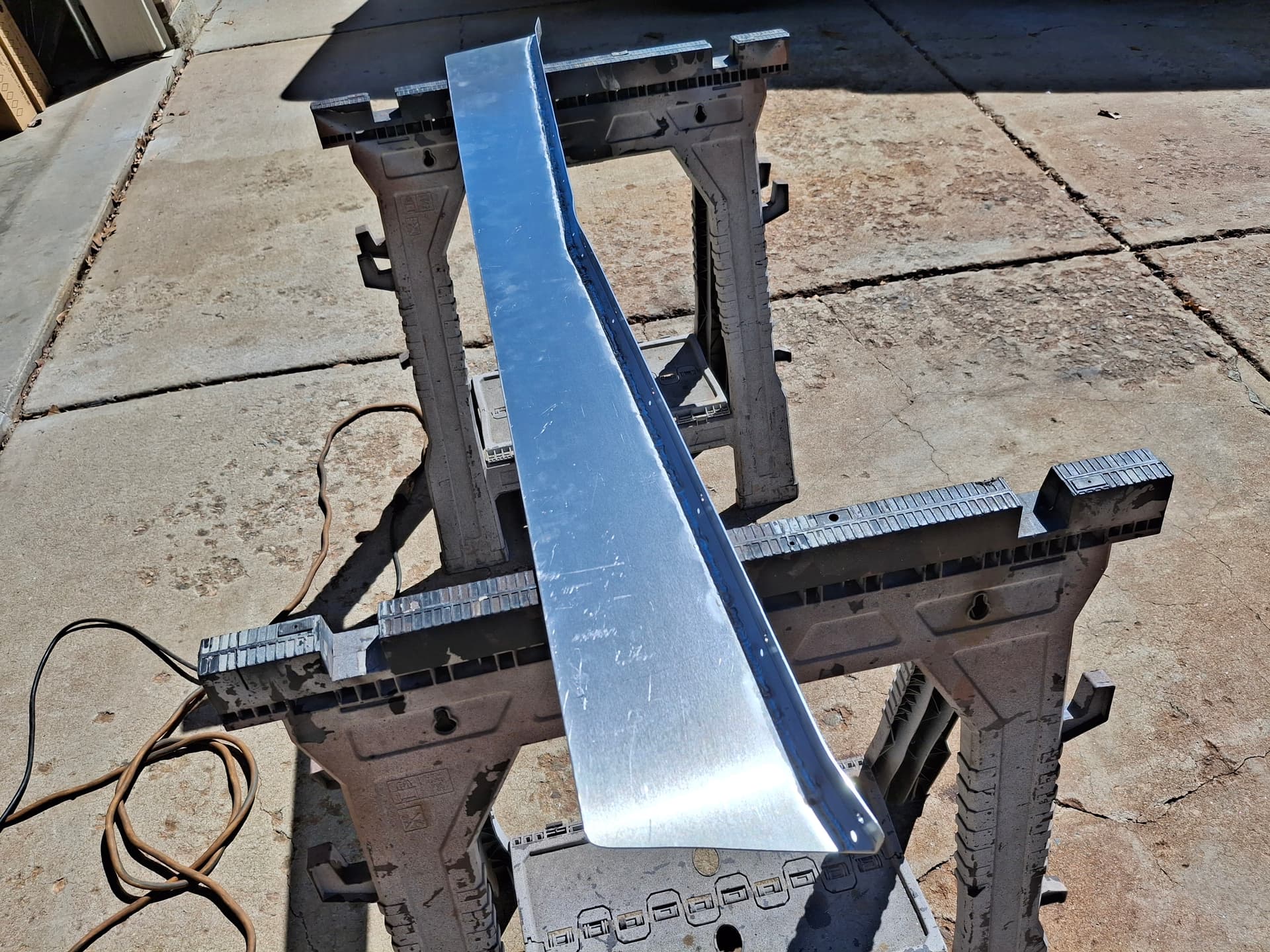
Although the spoiler was pretty rigid, it tended to flex the valance more than I liked when I applied force, so I welded 1/8" x 3/4" aluminum ribs onto the backside for bracing and on the ends to finish them off. I ran two 1/8" x 3/4" aluminum brackets from the front crossmember (drilled and tapped) to these ribs to secure the spoiler. All this support keeps the spoiler and valance from flexing and should withstand light damage from track gravel, chunks of tire, etc.
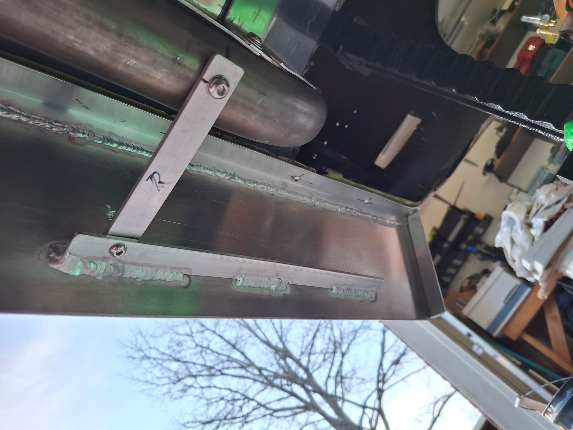
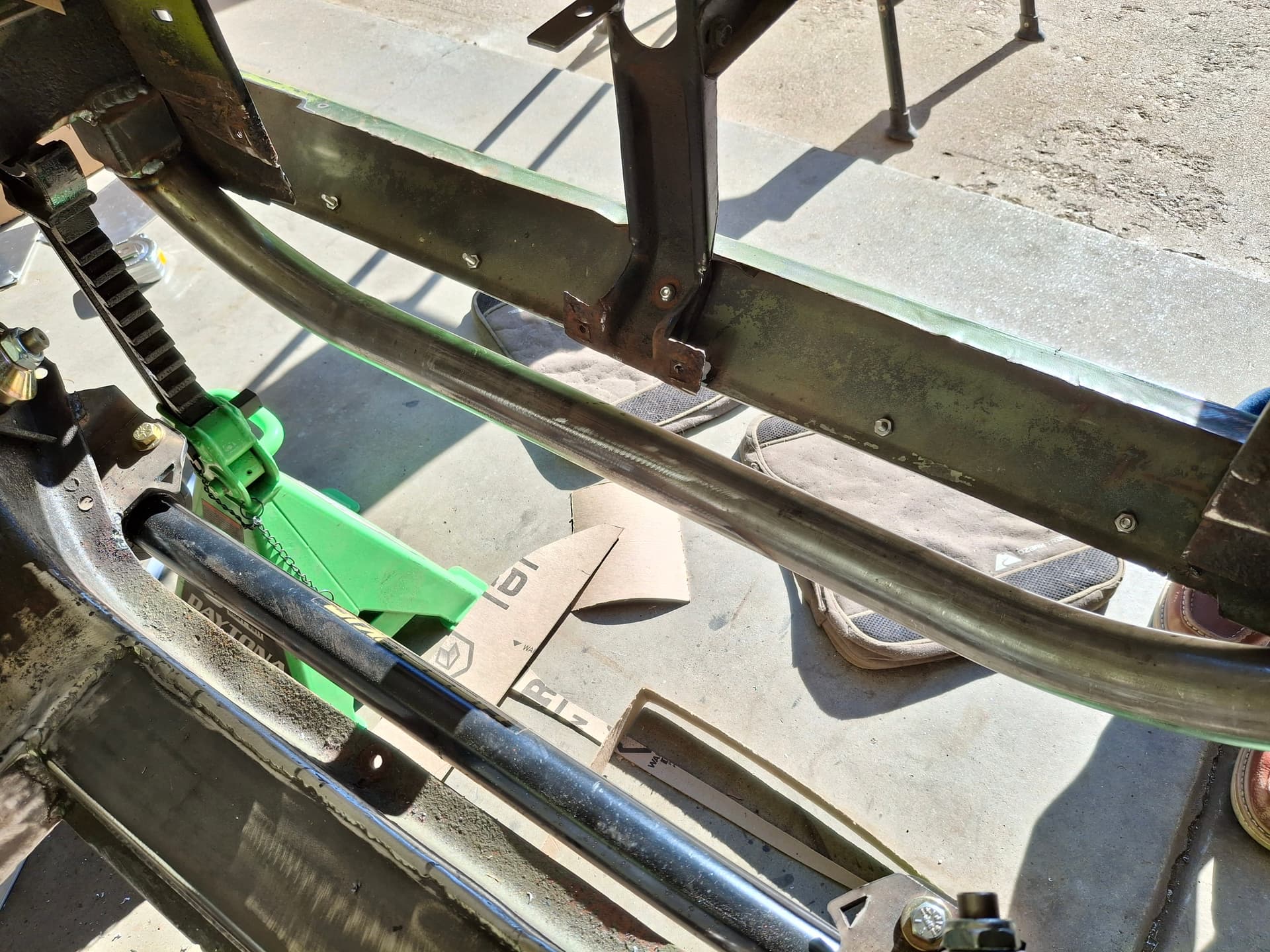
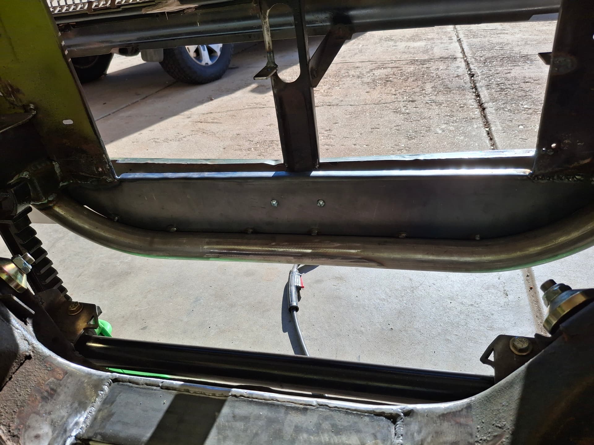
To address the large gaps between the valance and core support that would impede/trap air flow, I cut and fitted 20-gauge steel sheet to extend the valance in for a tight seal to the core support (currently tack-welded but will be finished and smoothed during body work). I drilled and tapped holes in the new lower core support panel to secure the valance at the back, which added even more rigidity to the spoiler system.
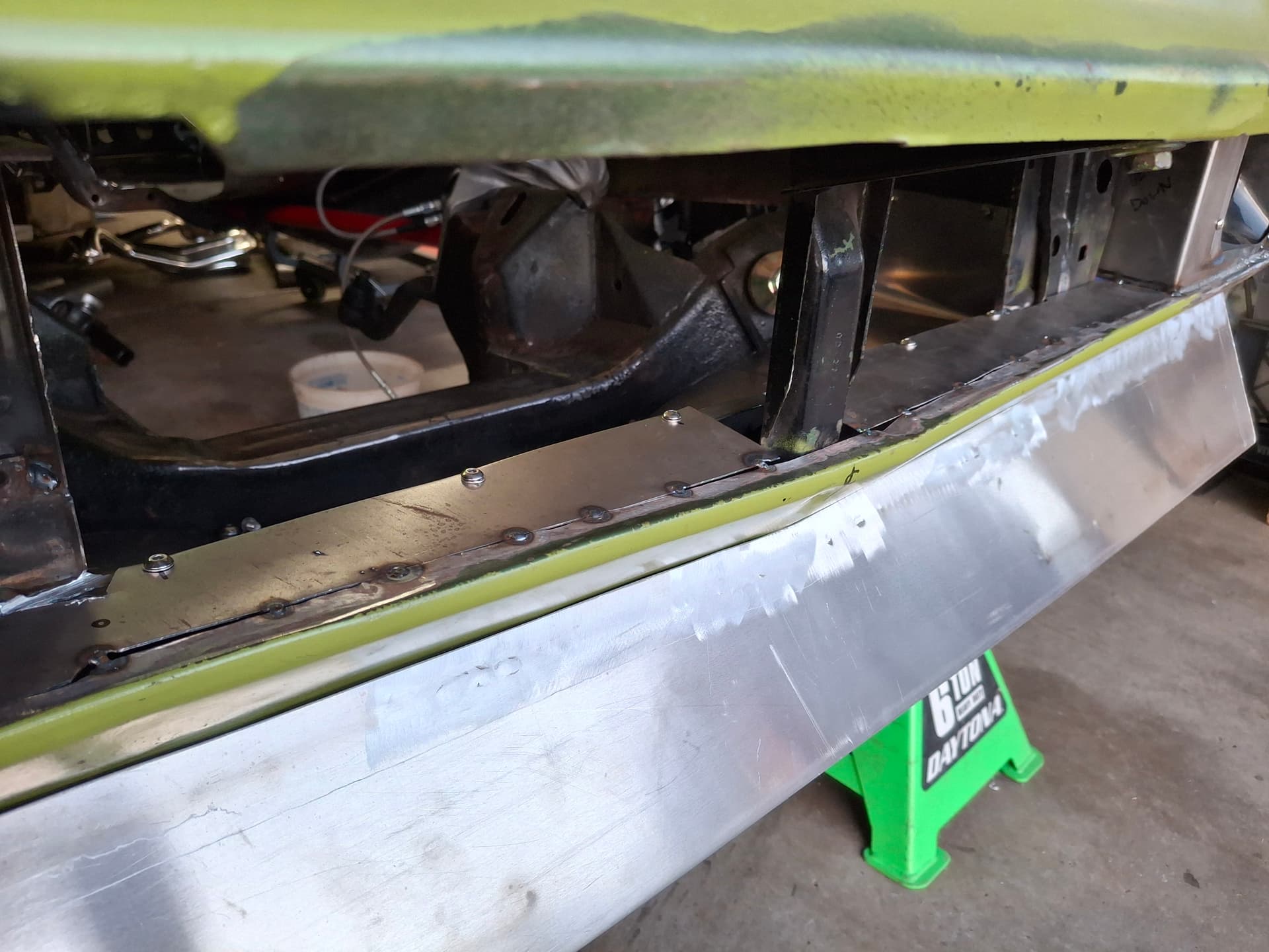
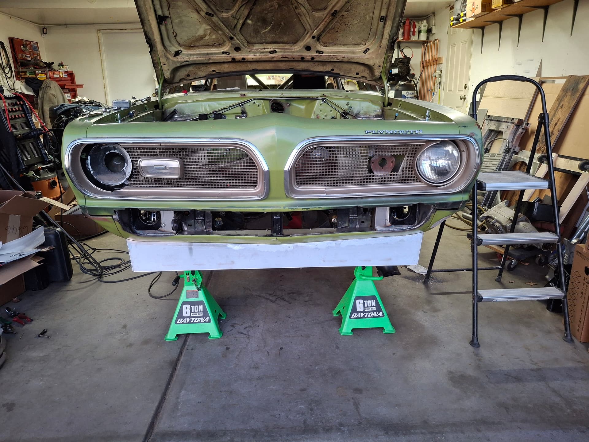
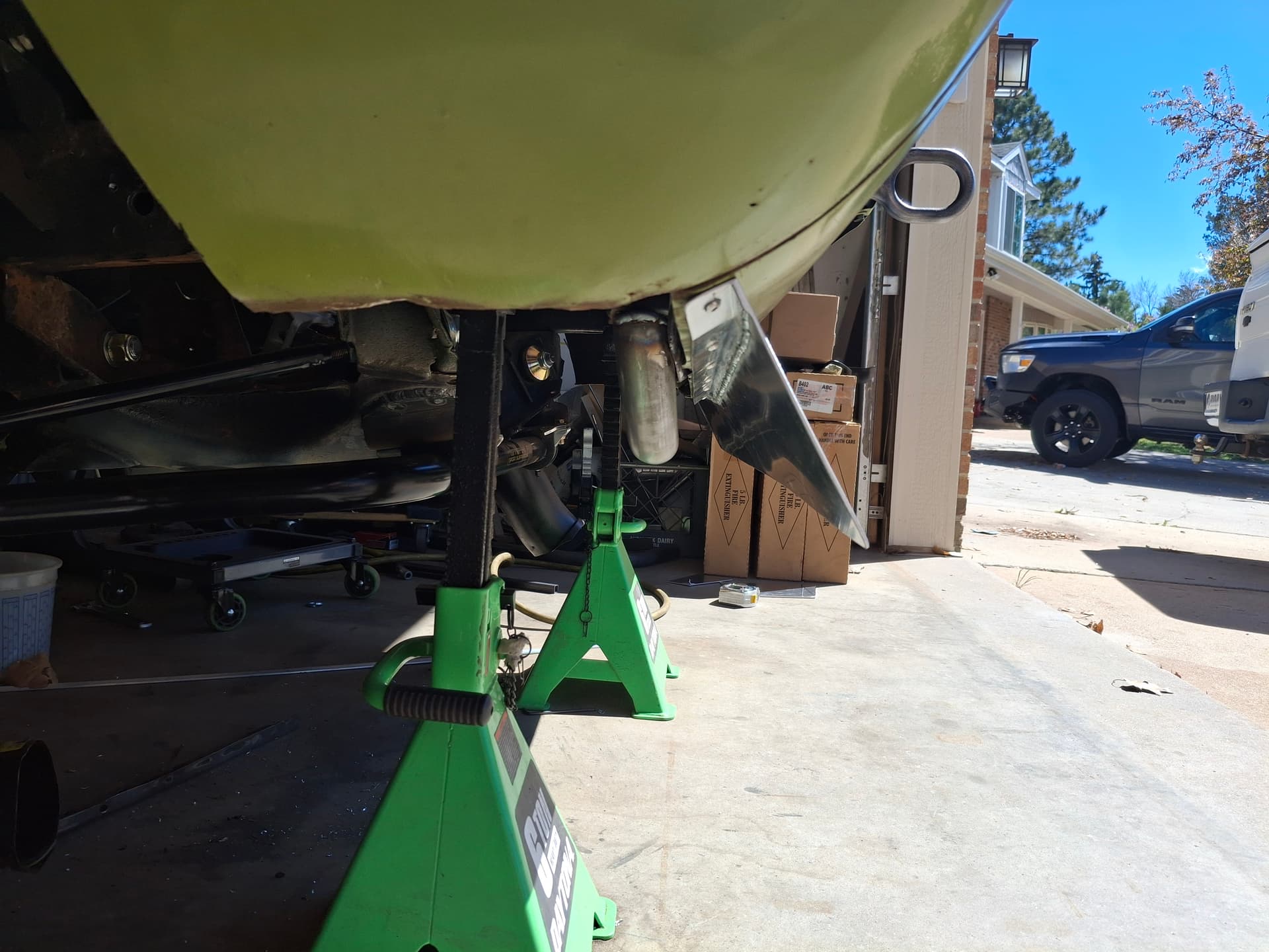
Lastly, I fabricated an air dam panel that covers the large area between the core support and K member including up the sides. I had to build it out of three pieces for installation, and it bolts to holes drilled and tapped in the subframe, front crossmember, and K member. Any air that gets under the spoiler now can’t easily flow up into the engine compartment, and the air coming out of the radiator will be directed around the engine before it can flow down.
Post Alert:
@jonUU
@Sportsracer
@Datsun78
@Bob_Alder
@Rich
@Nick_H
@jackson_prime101
1 Like
Nice looking work as always. Aero design and implementation are areas of hidden performance gains (hopefully) that can make or break a build as it applies to on track performance. As you’re building a car that was rarely chosen as road race car, and have some time, I would suggest you get a copy of, “Competition Car Aerodynamics” by Simon McBeath. While a lot of the book covers more modern cars there is a wealth of general info from a very qualified aerodynamic engineer. Some of it very technical but knowing what helps or hurts can make the trial and error period of building a race car less painful.
The book was recommended to me by a retired navy pilot who has a degree in aerodynamics. He is also a racer and has helped me with adding improvements to my race car. The difference in cornering performance is definitely noticeable, both in seat of the pants and in lap times.
Best
Tom
1 Like
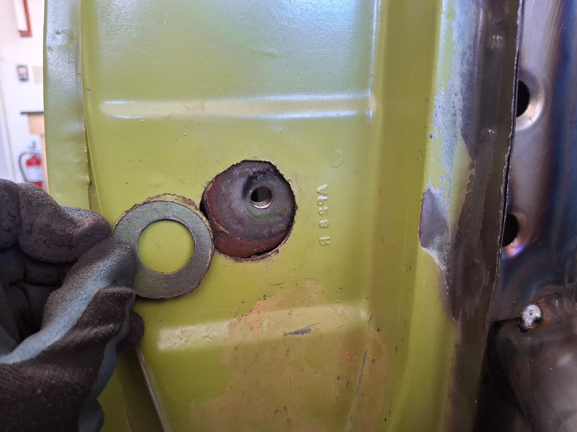
Door Latch Pins
In this installment, I tackle an odd issue with the door latch pins. Strangely enough, the door jamb sheet metal rusted through in a hairline around the pins, resulting in the pins walking around even though they were tight into the loose backing/adjuster plates. The pins took torch heat, penetrating oil, and a 16" pipe wrench to give up the ghost and loosen, but they were still useable after I cleaned up the wrench marks with a file.
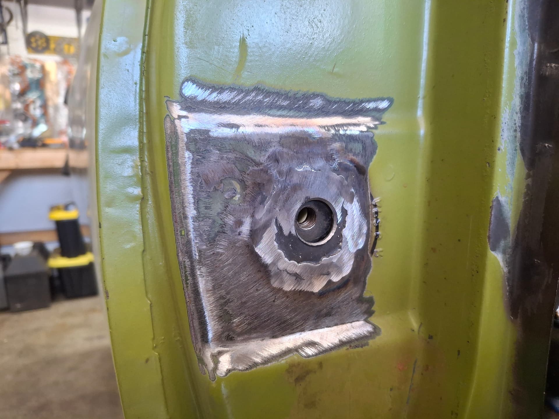
I traced the old pieces of door panel onto some 16-gauge steel, cut and fit them to the holes, drilled the pin holes, and welded them in place. The welds will get smoothed over when I do the bodywork. I also had to repair the backing/adjuster plate retaining brackets on the inside of the door jamb because they bent during loosening the pins and wouldn’t hold the backing/adjuster plates in place properly. With the repair, I was able to dial in and tighten the pins for a nice, tight door latch action.
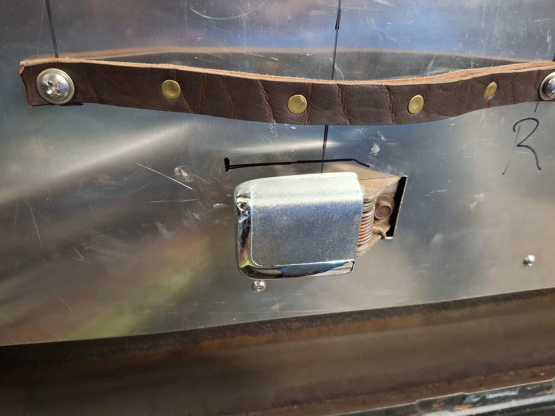
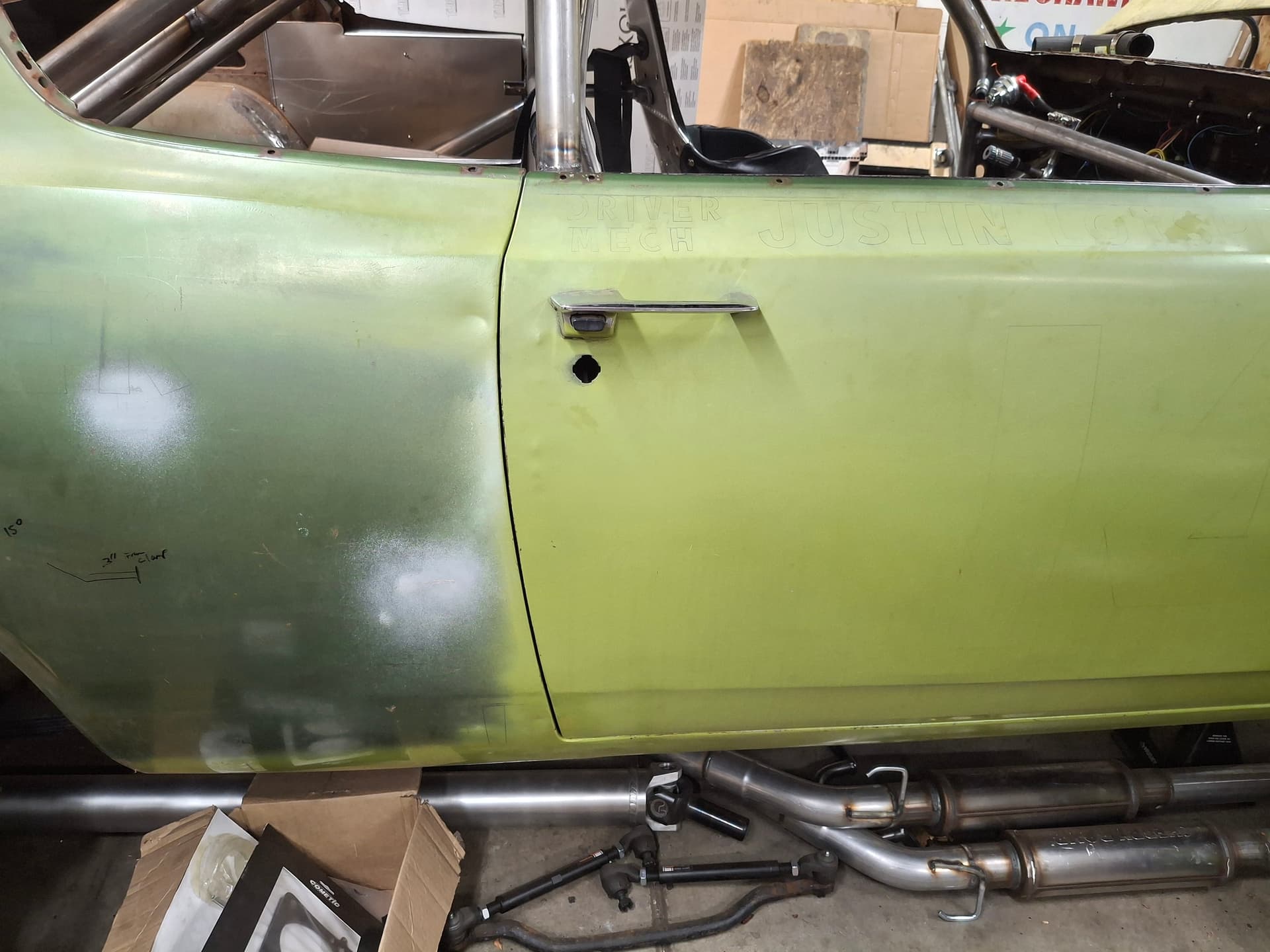
Door Latches and Handles
The door latch mechanisms were badly corroded with both not allowing the latch to actuate from inside the car. At over $100 each for new ones, I removed the old ones and drenched them in penetrating oil for a few days followed by a long heated Pine Sol bath in the ultrasonic cleaner. After some work with a wire brush, moving components, more ultrasonic cleaning, and straightening a couple levers that were bent from previous people trying to force the latch open, I was able to get both latches working smoothly both inside and outside. With ample white lithium grease, they went back in the doors only this time with the locking mechanism deactivated.
I only had one interior pot-metal handle, which was pitted so badly it was unusable. The other thing I didn’t like about the factory interior handles was their squared-off, sharper edges that would be easier for my gear to catch on. To resolve the issue, I did some digging around and took a chance that some handles out of a 1980’s Dodge van off ebay would fit. I’m happy to report that they share the same mounting configuration and fit perfectly, and their rounded corners will be less likely to snag things.
Post Alert:
@jonUU
@Sportsracer
@Datsun78
@Bob_Alder
@Rich
@Nick_H
@jackson_prime101
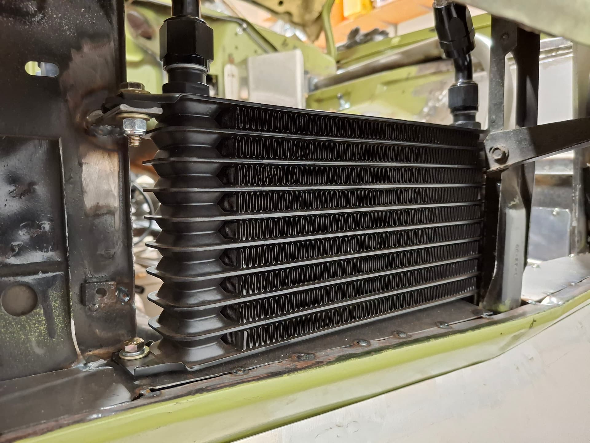
Finalizing Oil and Fuel Plumbing
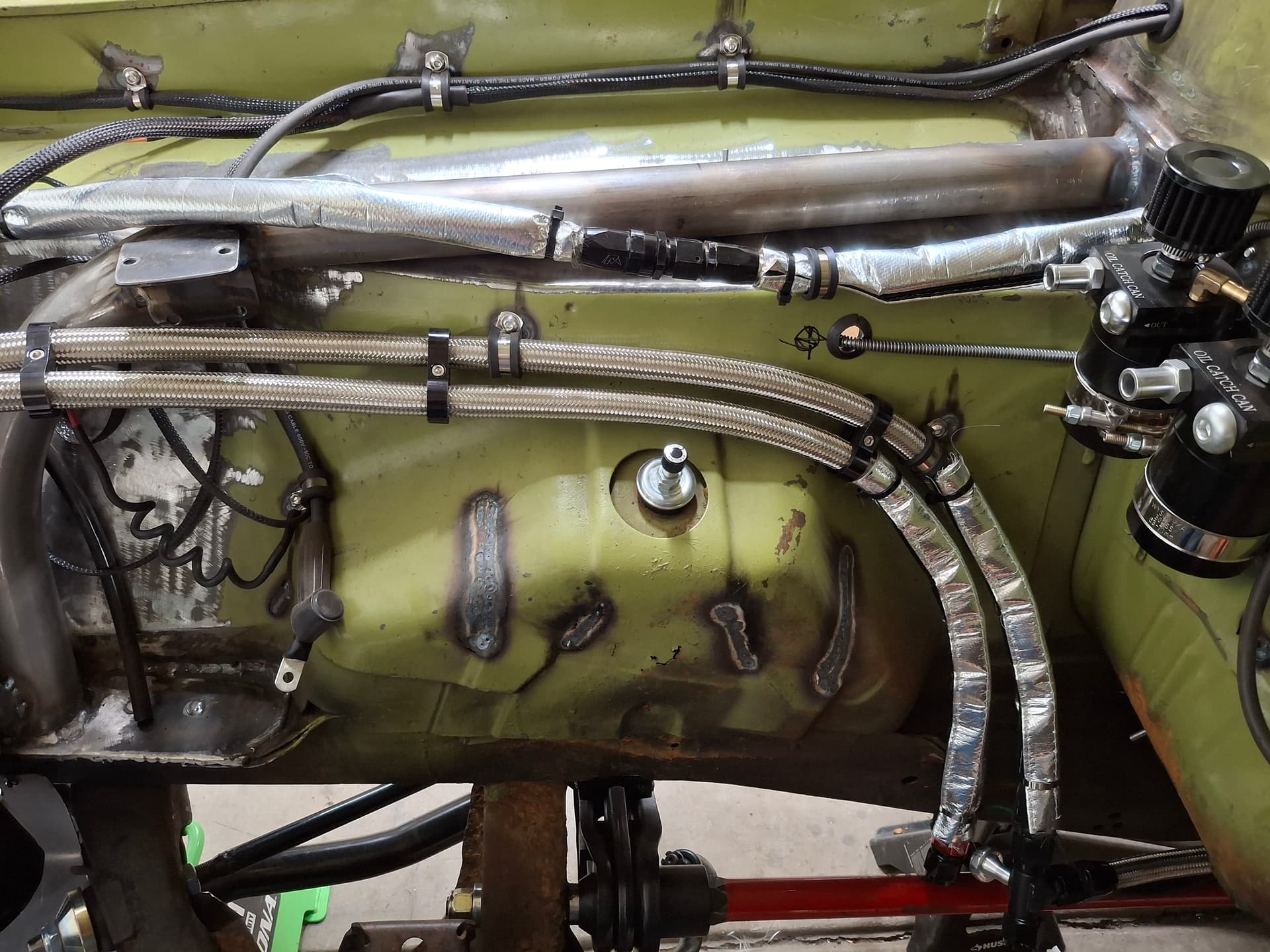
I did the final installation of the oil cooler with rubber insulators and tightened all the AN connections in the system. For the section closest to the exhaust, I wrapped them in fiberglass heat shield. I decided to leave the rest open to the air because the hole in the core support allows fresh air to blow over them providing additional cooling. I also applied the wrap to the fuel hose from the firewall to the carburetor rail. All the Adel clamps received star washers and final torque as well.
Oil Filter
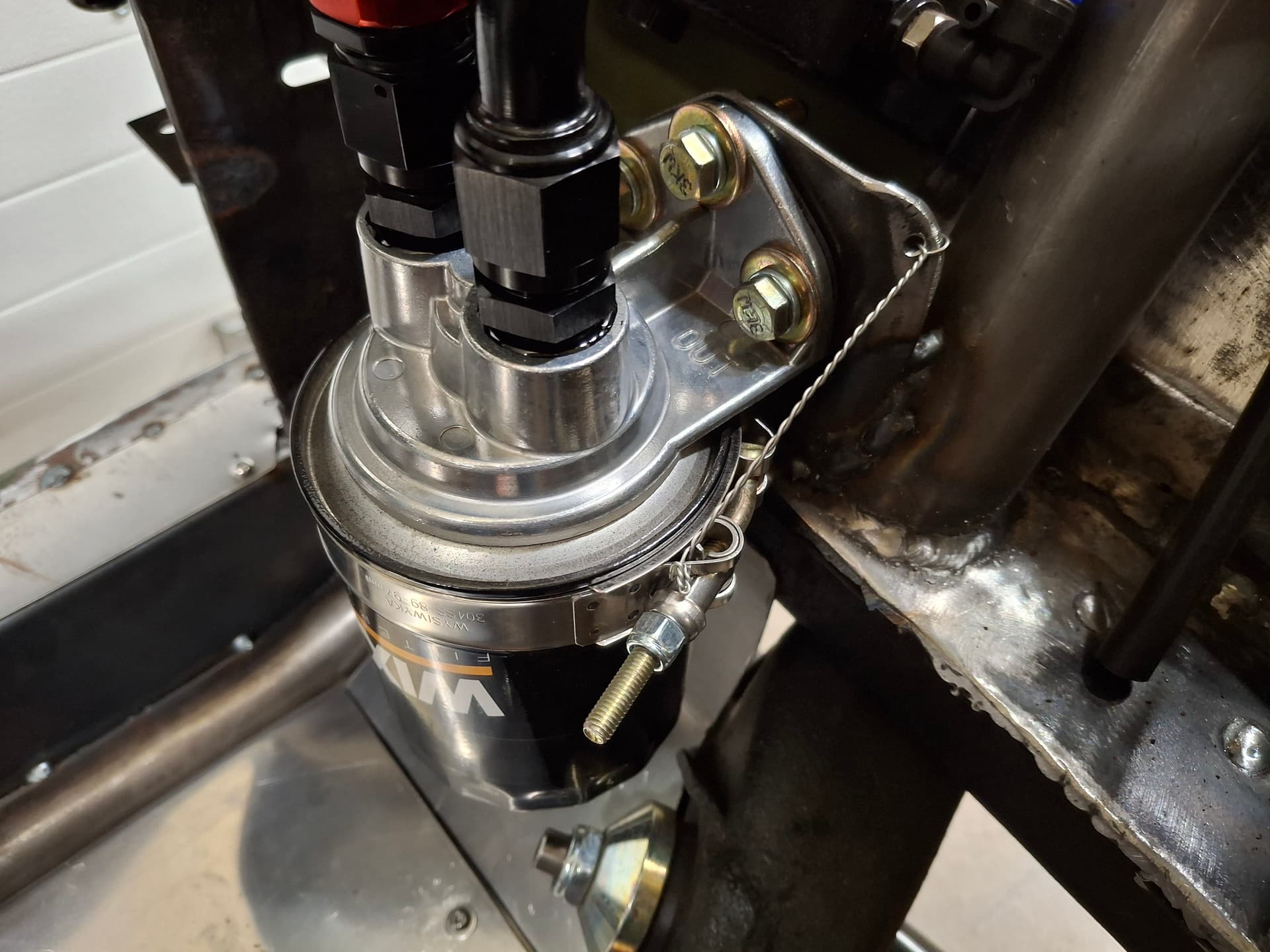
I felt a sense of seeing the end of the road ahead when I poured a quart of oil into the remove filter before spinning it on. I secured a hose clamp around the filter and safety wired it. Once I got the safety wire situated, I realized there is enough room for me to fabricate a permanent cable that attaches to the hose clamp via a hitch pin to where I don’t have to safety wire at each filter change, so I’ll fabricate that the next time I change the filter.
Coolant Expansion Tank Cap
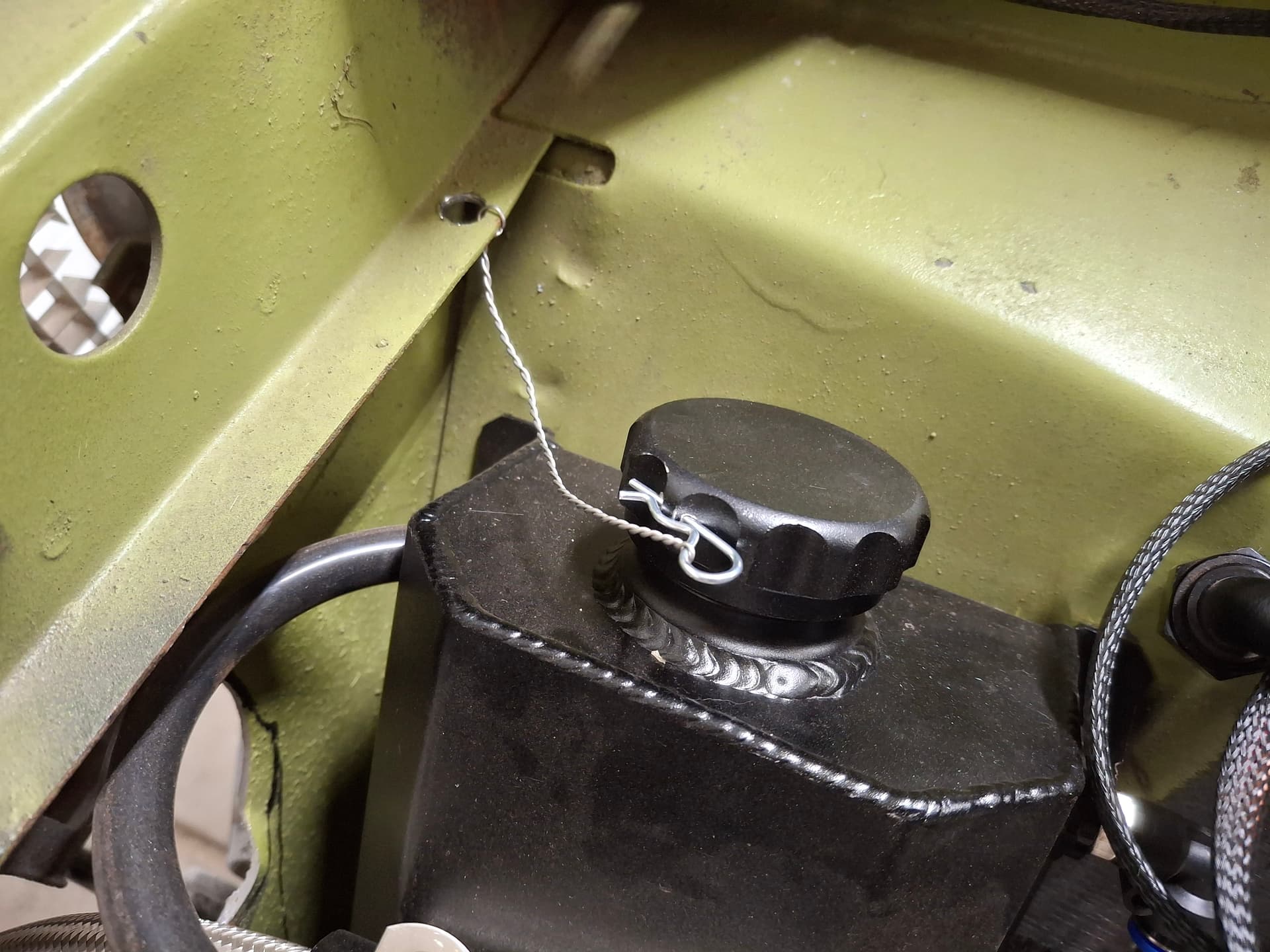
Using the lesson from the oil filter, I fabricated a permanent safety cable that attaches to the coolant overflow cap via a hitch pin after I drilled a hole in the cap.
Post Alert:
@jonUU
@Sportsracer
@Datsun78
@Bob_Alder
@Rich
@Nick_H
@jackson_prime101
1 Like
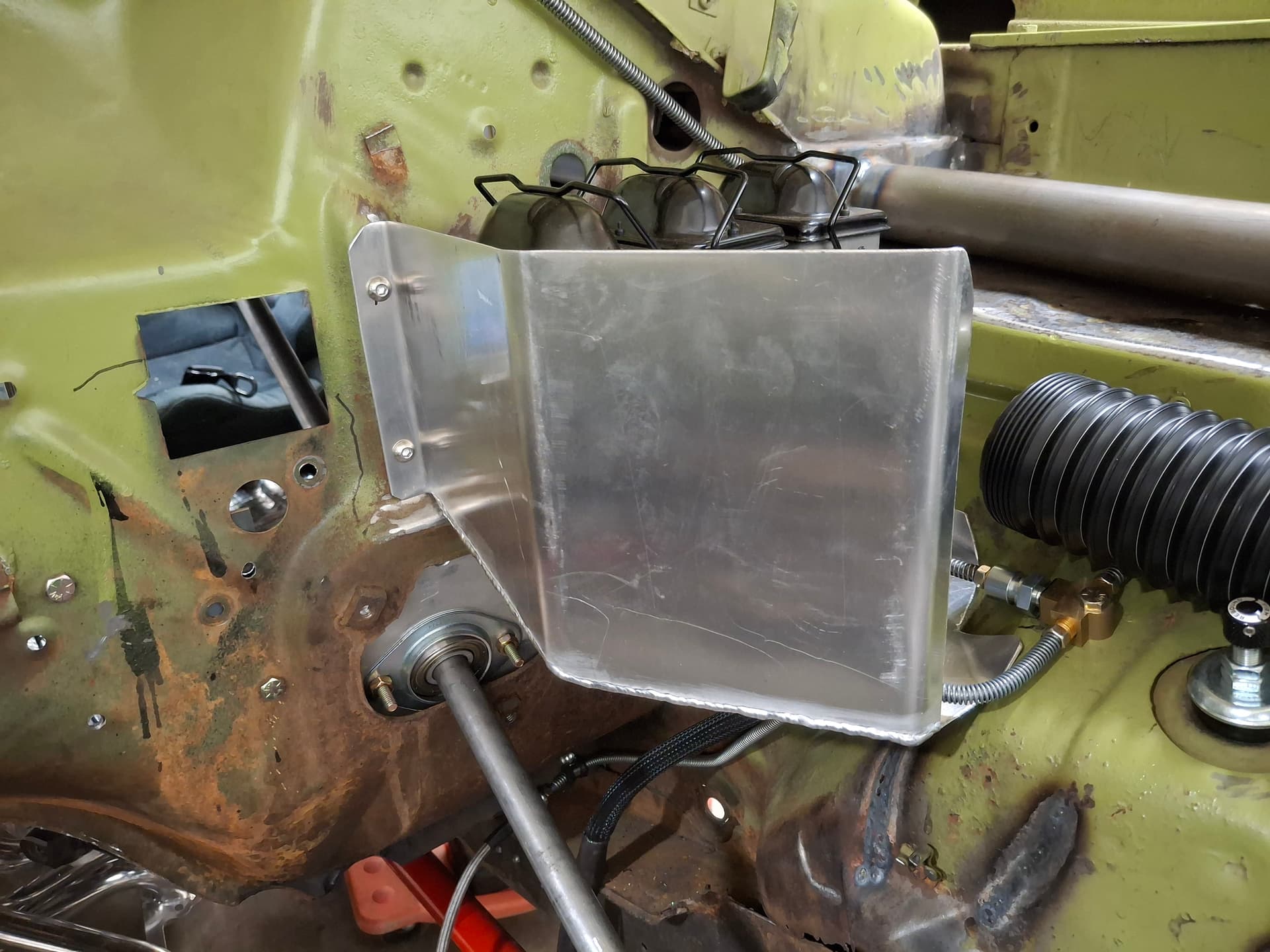
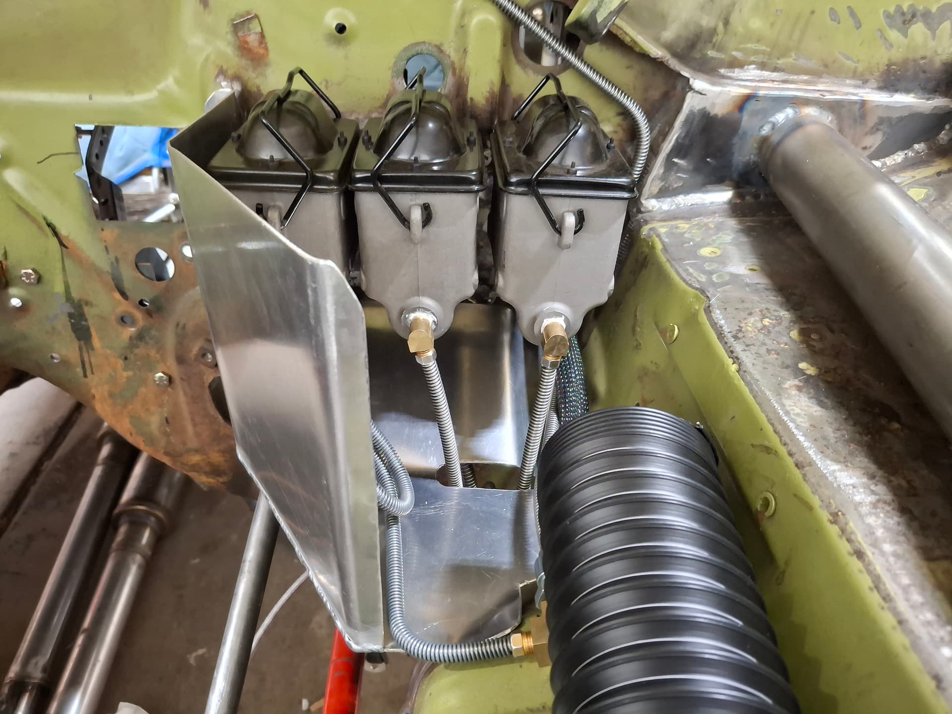
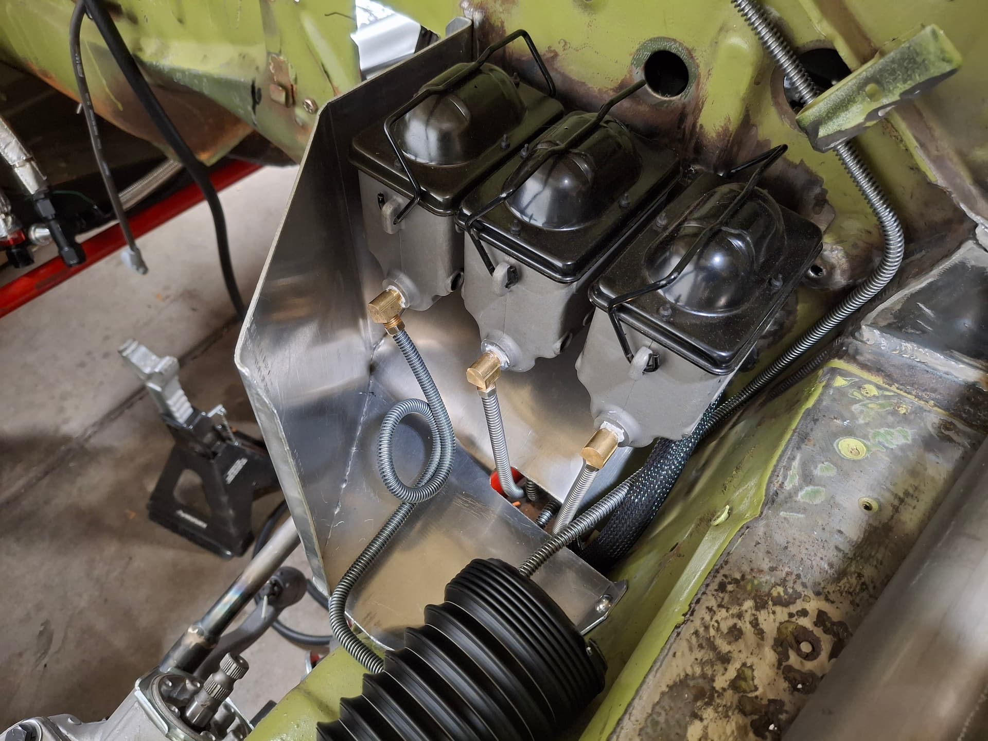
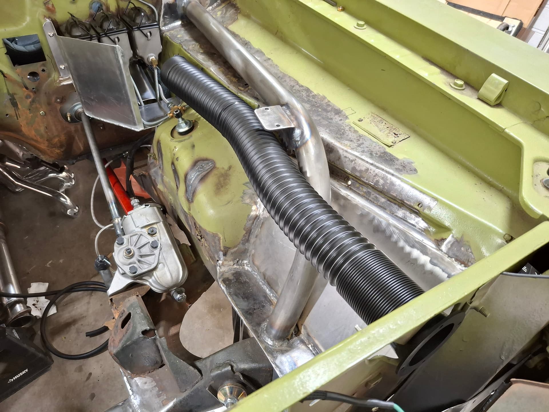
Brake and Clutch Master Cylinder Cooling
To help keep engine heat out of the brake fluid, I built an aluminum heat shield around the brake and clutch master cylinder assembly. There is a factory hole in the radiator core support for an optional A/C condenser that is just about inline with the master cylinders, so I decided to pipe in fresh air versus welding up that hole. I used a tapered carpentry sawdust collector for the inlet and 2-1/2" dust collector duct from there back to the heat shield. A couple Adel clamps and zip ties secure the duct to the inner fender.
Post Alert:
@jonUU
@Sportsracer
@Datsun78
@Bob_Alder
@Rich
@Nick_H
@jackson_prime101
It’s been a long time since I updated on the engine, but I’ve been working through it and struggling with parts quality and the resulting returns. I have a lot here, so I’ll break it down.
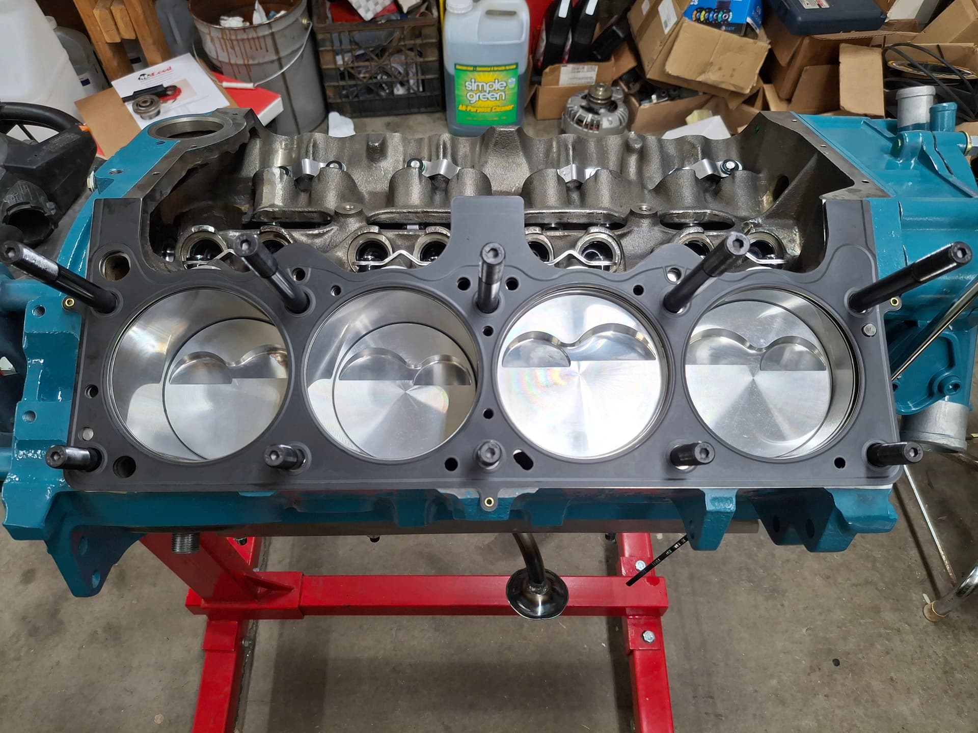
Short Block
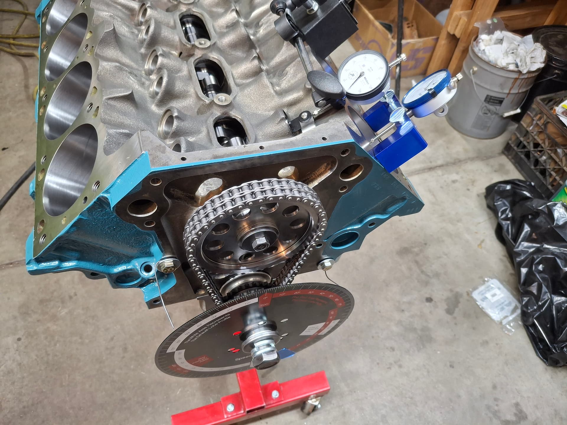
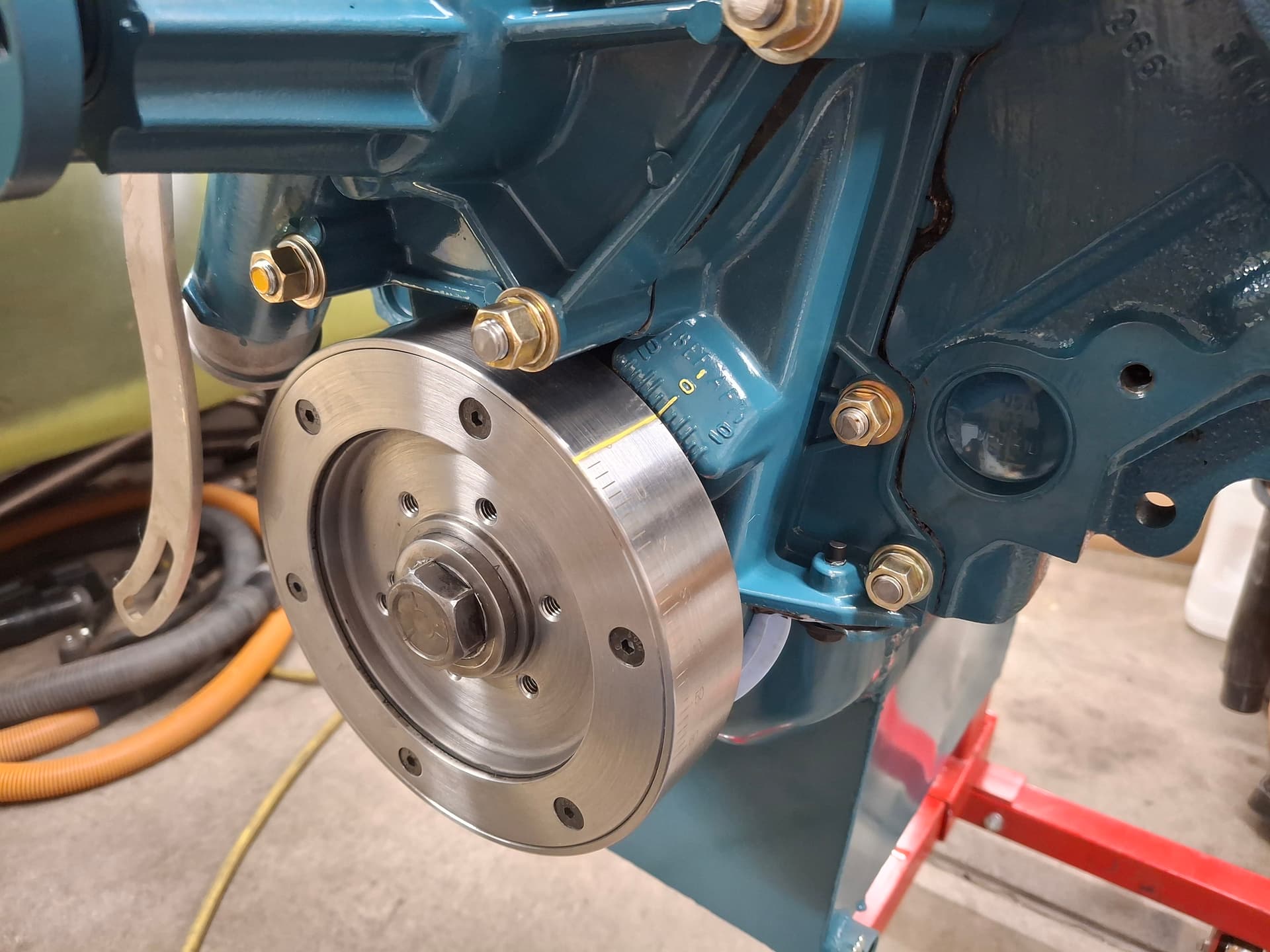
Nick Hill and I assembled the short block last month including the windage tray and oil-pump pickup I fabricated. Measuring all the bearing clearances showed clearances within spec on the loose end. Crankshaft endplay was also good. I located true top-dead center on cylinder 1 and then degreed the camshaft, which required 2 degrees of advance to bring it to the 104 degrees specified by the cam grinder. I temporarily mocked up the timing cover and harmonic damper and filed a new TDC line on the damper aligned with the tab on the cover.
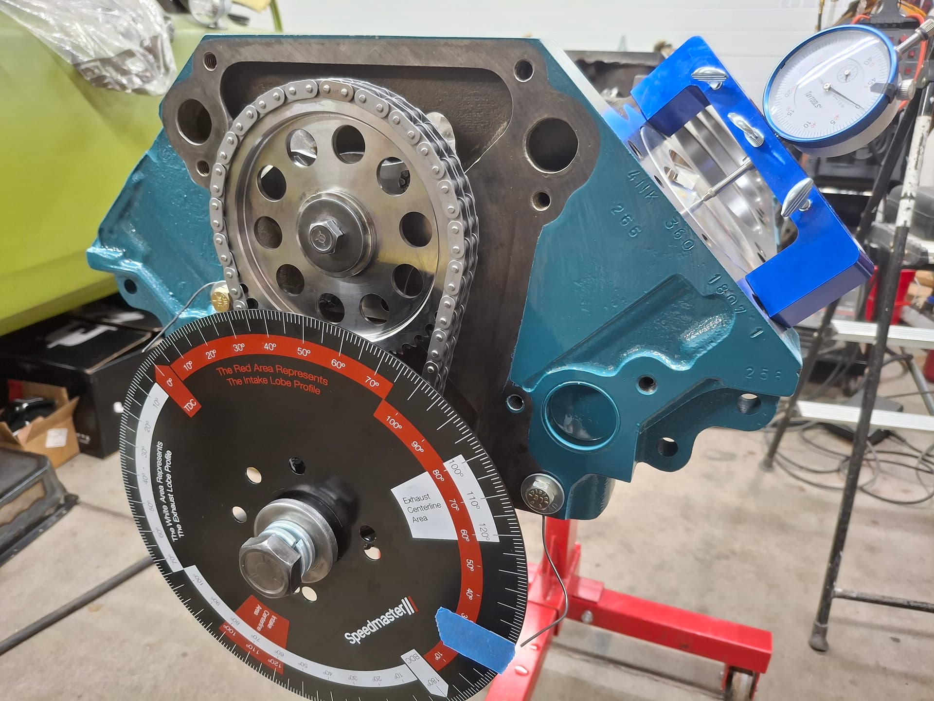
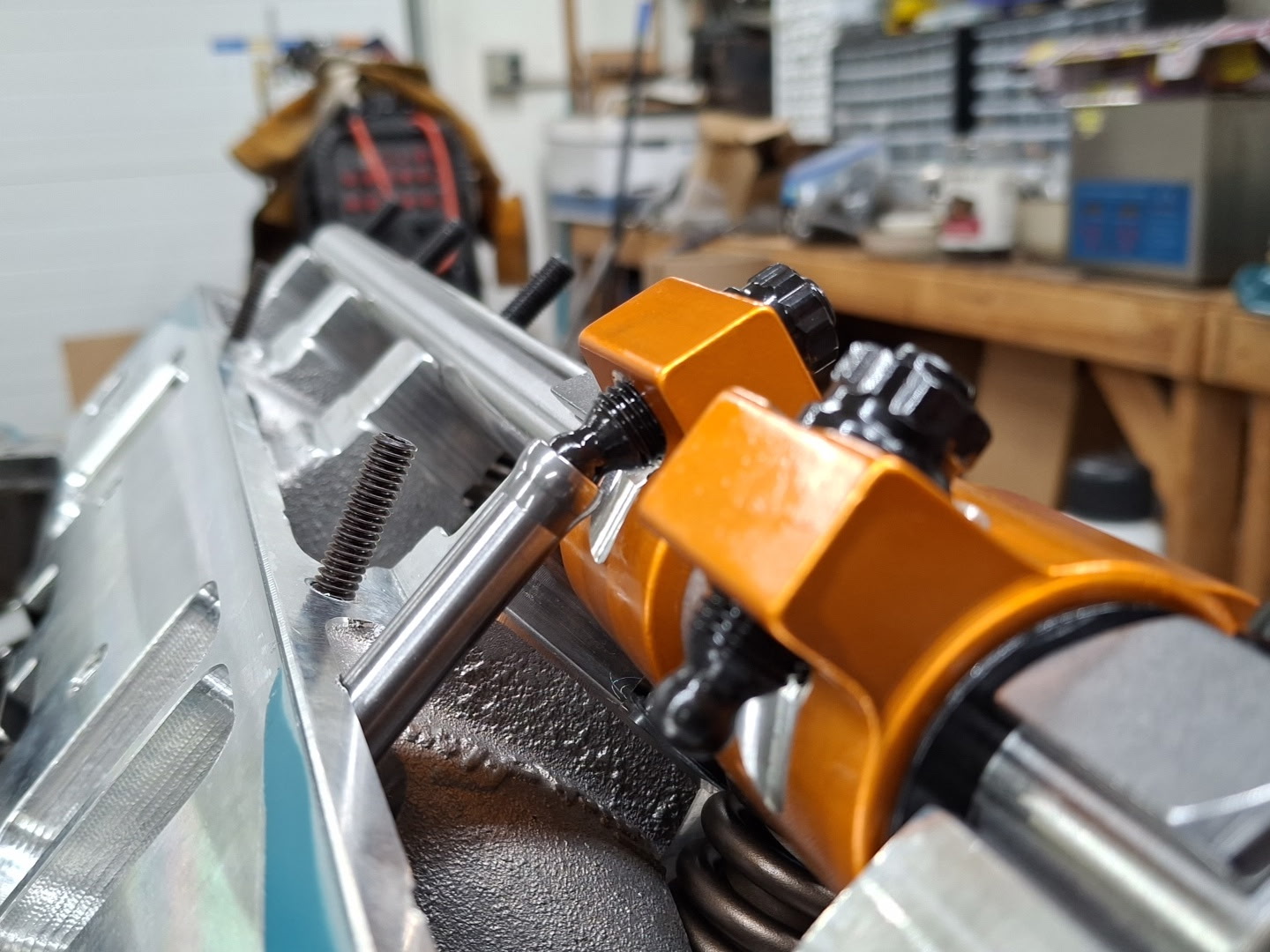
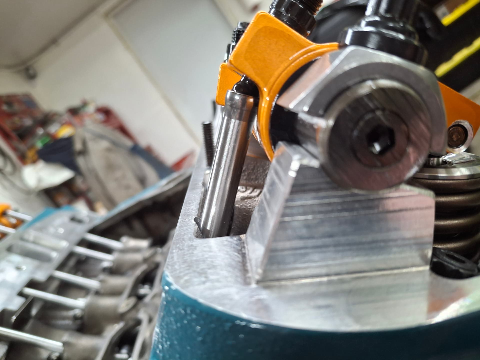
Valve-to-Piston Clearance and Push Rod Length
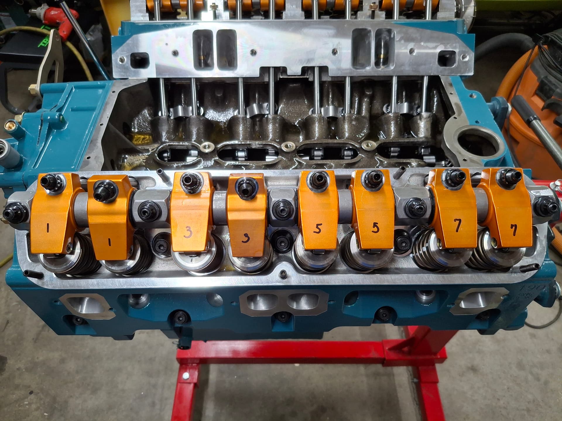
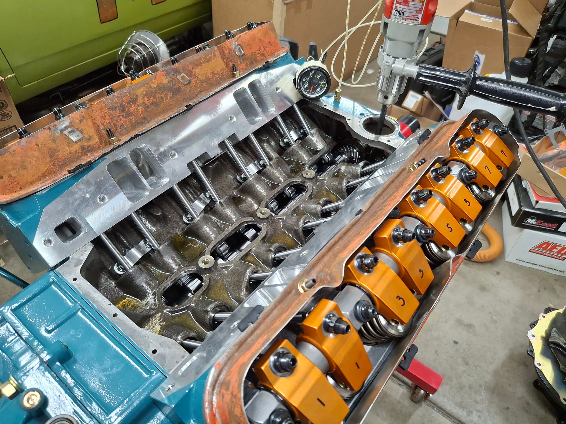
Note that the photos show me using the first set of red Harland Sharp roller rocker arms to check clearance, but later photos show the upgraded gold Harland Sharp roller rocker arms after I found quality issues with the first set and had to jump through hoops getting an exchange. I ran valve clearance with both assemblies with the same results. The intake and exhaust clearance came out with more than plenty on both accounts. In an ideal world, the piston valve reliefs don’t need to be as deep, which would improve quench and compression ratio, but I’m not a piston manufacturer. Radial clearance between the valve and reliefs was also plenty.
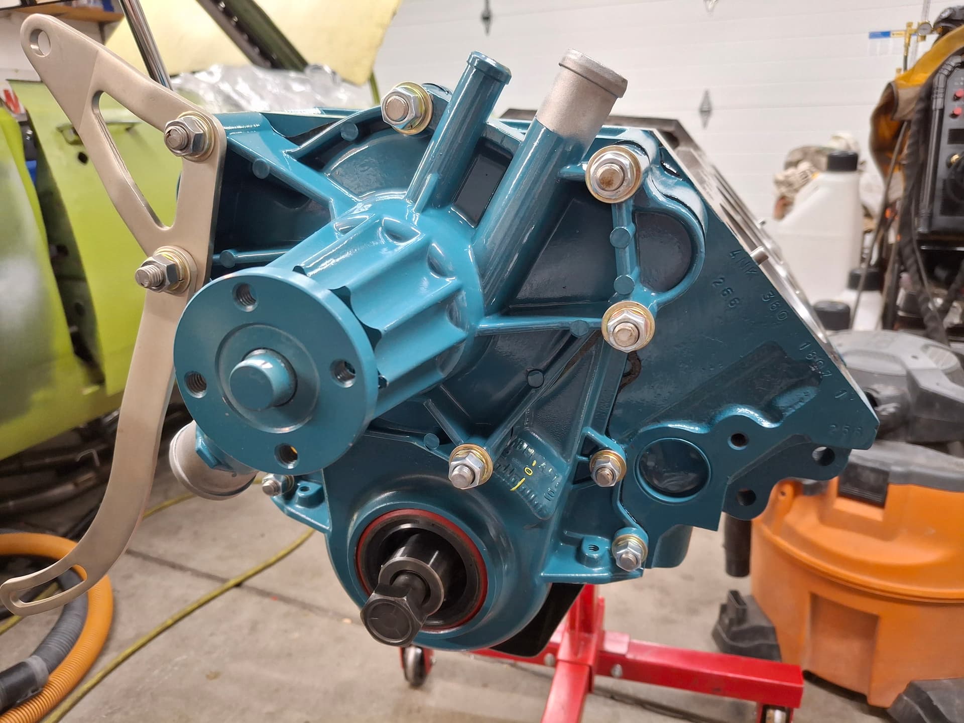
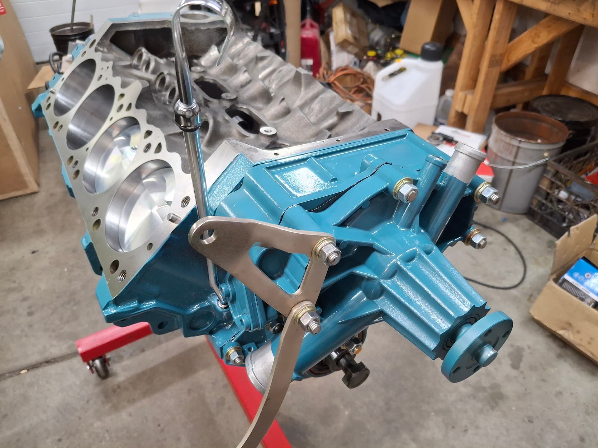
Timing Cover and Water Pump
While I will argue all day long that Mopar was one of the more advanced engine and car designers, some designs they kept since the 1950s puzzle the heck out of me. One of them, which isn’t uncommon outside of Mopar, is bolt bosses going through to coolant or oil. In particular, there are four timing cover/water pump bolt bosses that go to oil and three that go to coolant. Unsealed, these have a tendency of leaking. A particular problem is that one of these bolts that goes to coolant is the lower alternator bracket bolt that must be loosened to adjust the belt tension. So even if you goop up the bolt threads with sealant when installing the timing cover/water pump, that seal breaks as soon as you need to make belt adjustments in the car. Essentially, every time you need to adjust the belt, you must remove the bolt and reapply sealant, make the belt adjustment, and torque down the bolt. Then there is the corrosion of the bolts that can make removal of these 6" long bolts difficult. I can’t remember how many broken, seized bolts I’ve had to extract from Mopar blocks over the years. Having done that dance enough, I purchased 316 stainless steel rod (about Grade 5 hardness) and cut up studs that I sealed into the block, so hopefully I’ve solved the issue of weeping bolts. The studs also allow me to use lock washers to help with the vibrations of track duty.
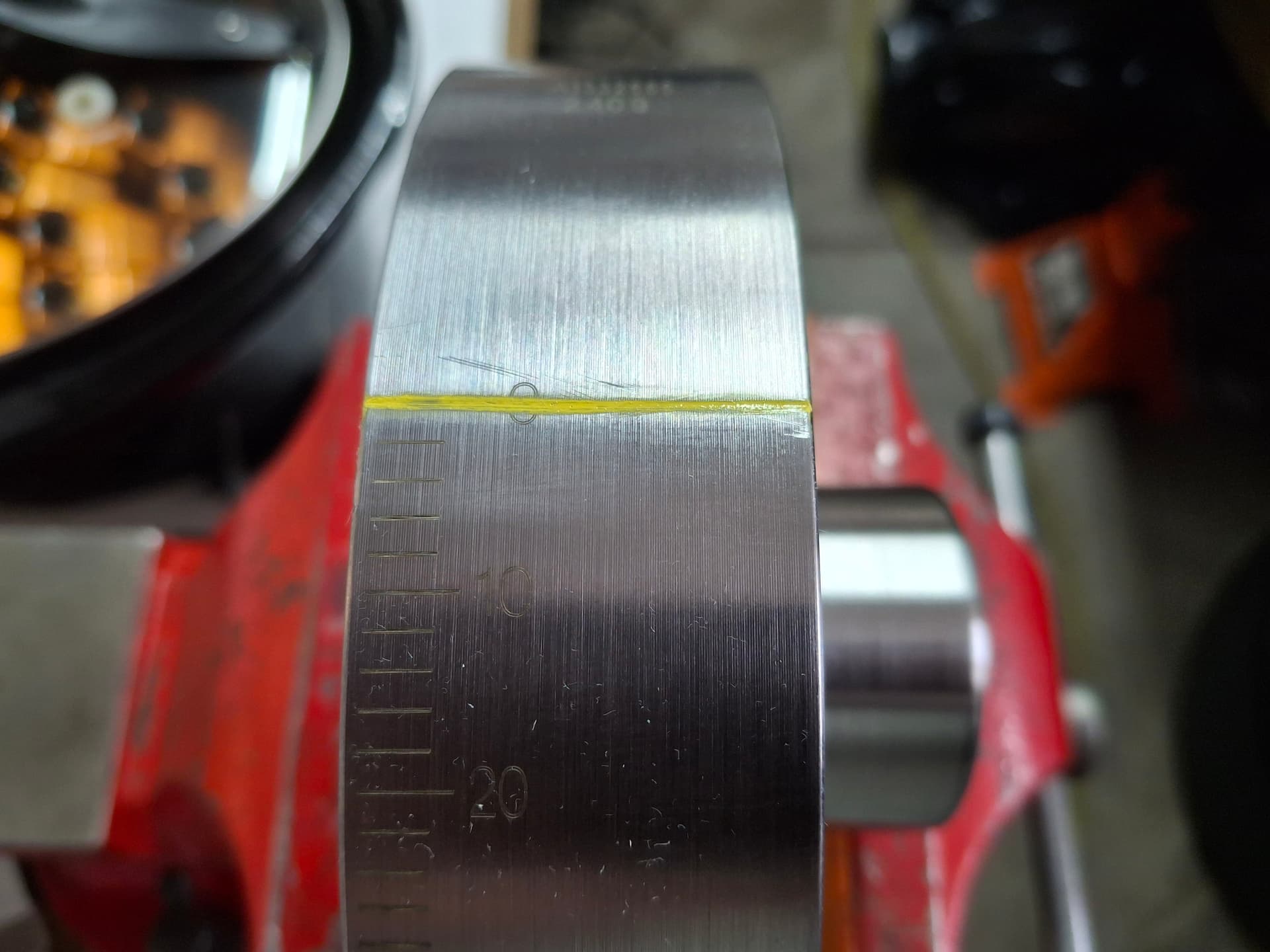
Harmonic Damper
After I had Denver Balancing balance the harmonic damper and pulley assembly (it was 5 grams out), I painted the new TDC mark and I installed the damper.
Dipstick Tube
Replacement dipstick tubes are straight, but they run into the fuel pump (the block-off plate in my case). I bent a jog into the tube, applied some sealant, and drove it home into the block using a junk open-end wrench laid flat against the lower flare of the tube. During the initial oil fill (keep reading below), I remarked the dipstick at 7 quarts with a center punch mark, which places the oil just below the pan’s sump baffle. The pan holds 9 quarts to bring the oil level to the factory position, but I’m going to try and keep it lower to decrease windage. If I see any oil starvation issues or win the lottery, I can bump up to 9 quarts.
Oil Pan
After media blasting (thanks @Bob_Alder for the use, again) and deep-cleaning the oil pan, I painted it. The drain plug got a hitch pin to secure it, the sump baffle bolts got safety wire, and the oil temp sending unit got installed. I used a 1990’s Magnum one-piece rubber gasket with RTV in the corners versus the older four-piece cork and rubber gasket setup, which is supposed to be better for sealing and is certainly less work installing.
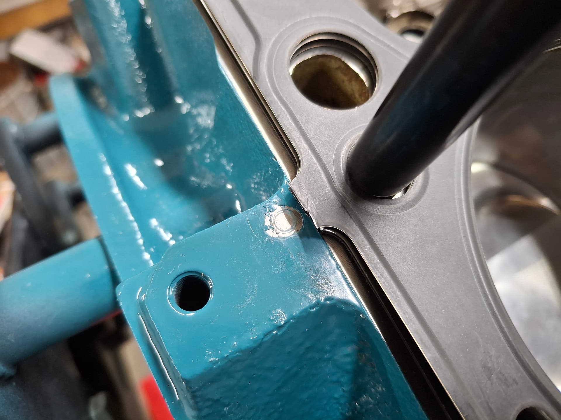
Cylinder Heads
I installed the head studs and began installing the heads when I noticed an issue on the right head gasket. The Cometic multi-layer steel gasket has three rivets that hold the layers of gasket together. The package instructions go to great lengths with a diagram to remind you to ensure these rivets stick out away from the mating surface. However, the rear rivet on the right head is misplaced and got sandwiched between the head and block deck and would have stopped the head from seating. I found this issue after I initially began snugging all the nuts to 20 lb.ft. before starting to actually torque them. Ideally, I would have known about the issue earlier and would have ground down this portion of the block. I didn’t want to grind on the head, and rather than risking metal shavings in the assembly, I simply cut off the rivet tab since the studs and other rivets held the gaskets in place just fine. After torqueing the heads in place, I installed studs for the valve covers.
Rocker Arm Assembly Woes
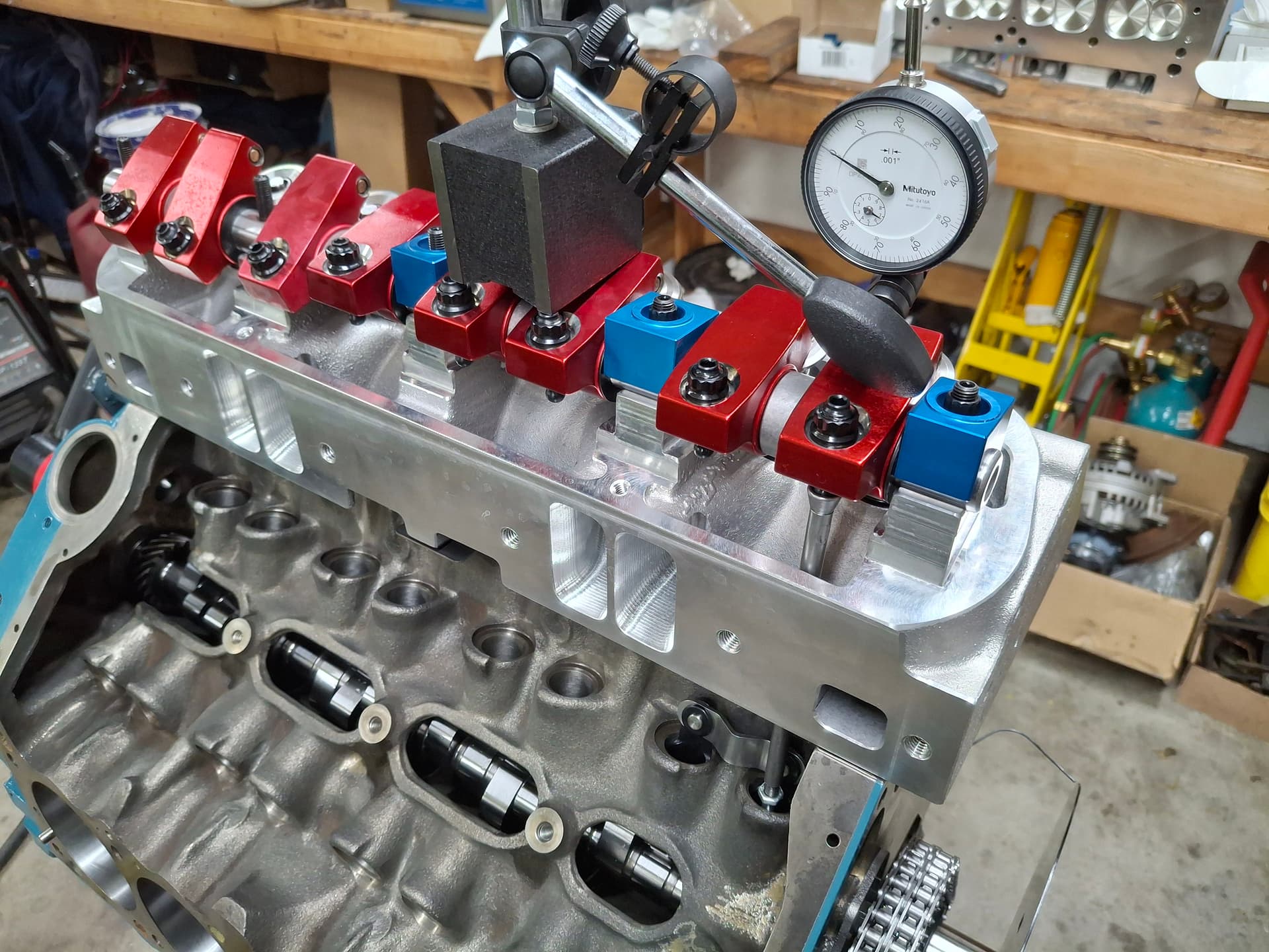
I could write a book on these issues, but the first set of Harland Sharp roller rocker arms I received had major quality issues I didn’t realize until after I measured the push rod length and ordered and received push rods from Smith Brothers. I upgraded to a Harland Sharp full needle-bearing roller rocker arm setup and then found I needed shorter push rods with them, so Smith Brothers got more of my business (sound familiar @jonUU?) . Here’s where things get really strange. The Harland Sharp instructions are very specific that a certain number of adjuster threads must show sticking out of the bottom of the arm body in order to “properly align the geometry.” However, when I mocked up the assembly per those instructions, the push rod and ball adjuster connection created a very apparent angle at 0 lift and a nasty angle at full lift. The push rod also contacted the cylinder head at full lift even after I hogged out those channels earlier during mockup with the other rocker assembly. Maybe the issue is that I’m using a pretty high-lift cam, but I did not like the geometry at all.
I experimented and found that if I kept the adjuster up in the body 0.120" (about 2 threads), the push rod and adjuster are darn near straight in line at 0 lift and have a much, much lighter angle at full lift, and the push rods had much more clearance to the head. Keep in mind this is a shaft-mount system, so changes to the adjuster/rod length on the push rod side don’t impact the tip’s location/sweep on the valve stem like they do on a Chevy or Ford. But what you are probably wonder is what does decreasing the adjuster’s thread engagement do to strength? Will the aluminum threads in the body strip out? I had the same worry, and math helped sooth it.
The rocker arms are made of extruded 2024-T3511 aircraft aluminum. If I installed the adjusters per Harland Sharp’s instructions with the terrible angle and clearance, I would have 0.575" of thread engagement (about 11.5 threads) versus 0.455" (about 9 threads) if I kept the adjuster up higher for better geometry and clearance. The adjusters are 7/16-20 alloy steel. On the low-end calculation, the stripping yield strength of the aluminum with 0.575" of thread is a whopping 16,000 lbs. If I decrease the thread engagement to 0.455", the stripping yield strength is, still, a whopping 13,000 lbs. My open valve-spring pressure is 560 lbs. (closed is 220 lbs.) So installing the adjuster per Harland Sharp will give me over 28 times the yield strength of my spring pressure, and installing the adjusters shallower with give me over 23 times the yield strength of my spring pressure. I might be making a very, terribly expensive and stupid mistake, but I went with better geometry and clearance over the Harland Sharp instructions and ordered the second set of longer push rods.
The other consideration is that at full lift, the rocker-arm ratio will be less with the adjusters installed per the instructions compared to the adjusters installed higher up since the contact point moves closer to the fulcrum at high lift. I checked lift at the spring retainer with the adjusters higher up and didn’t find an appreciable difference that would impact valve clearance.
After I received the push rods and mocked up the assembly, I found a pretty nice tip-to-valve wear pattern. It is very narrow and just off center to the outside, but the only way to change the tip location is by having a machinist make custom crescent shims for the rocker shaft towers to move the shaft inboard toward the lifters, which I’m not going to do for my purposes. If it were an IMSA engine, sure, but it’s not. I also checked the springs for coil bind and seal-to-retainer clearance, and all is good there.
Adjusters Installed Per HS Instructions with Sharp Angle at Full Lift:
Adjusters Installed Higher Up with Shallower Angle at Full Lift:
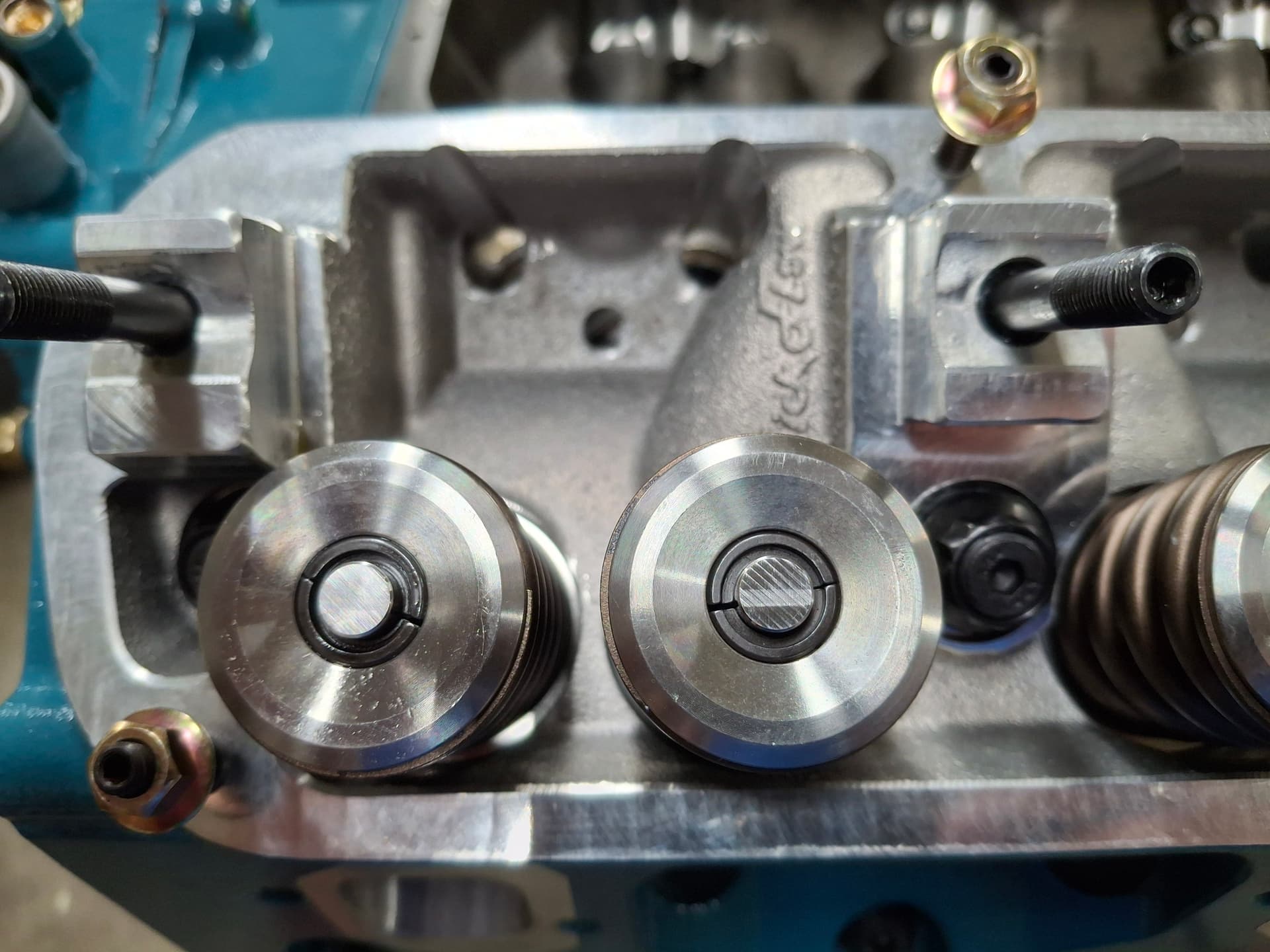
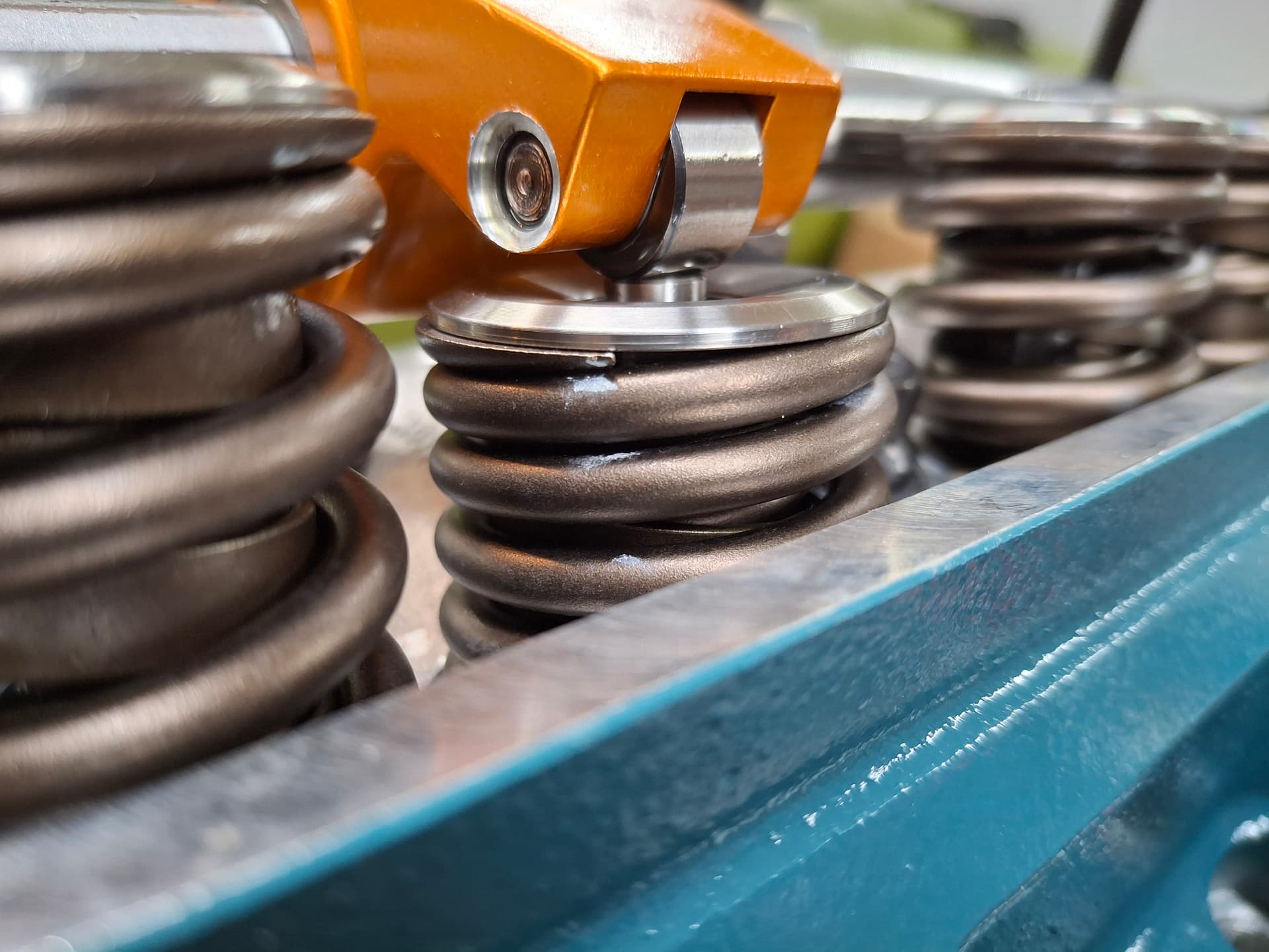
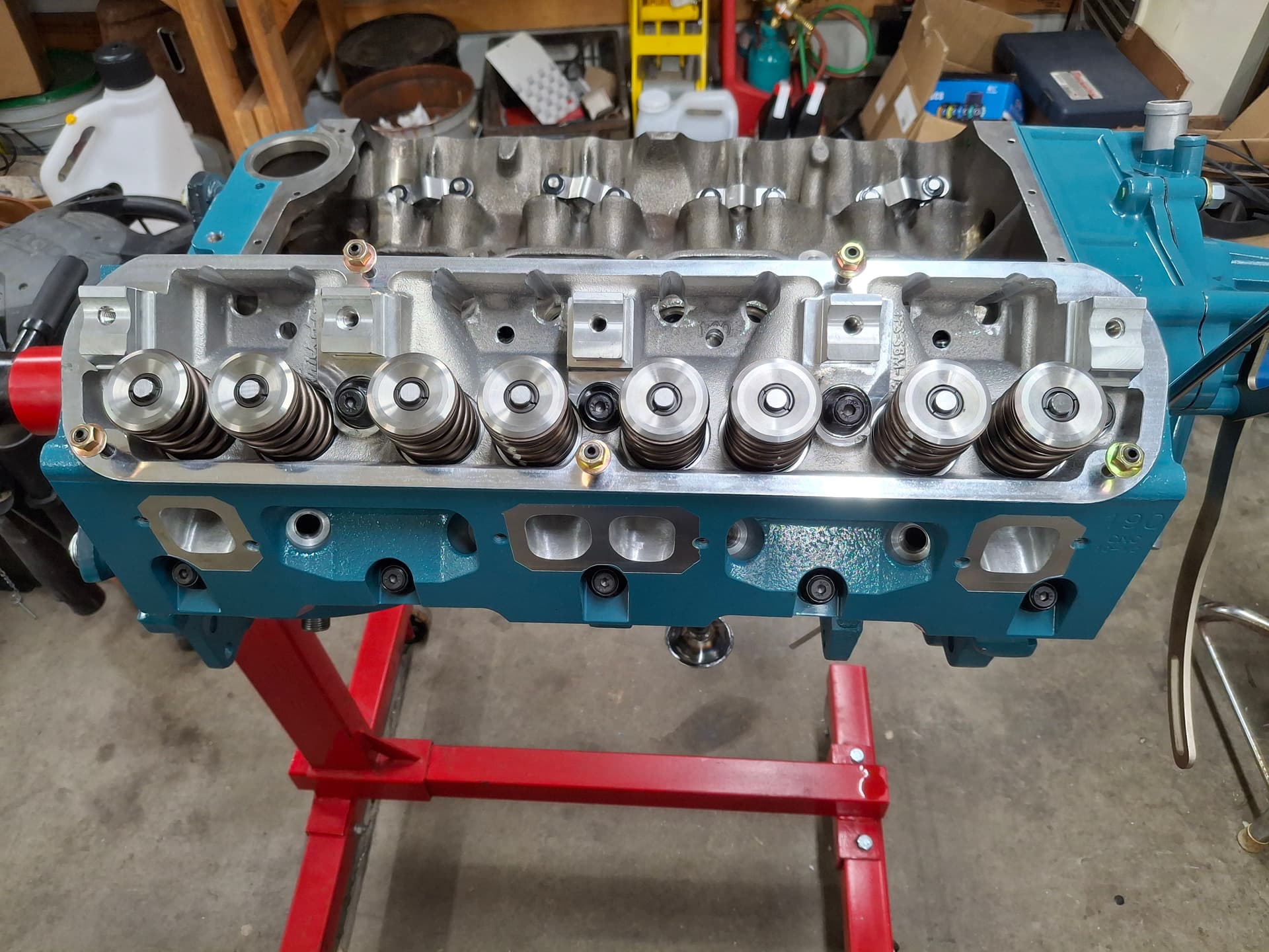
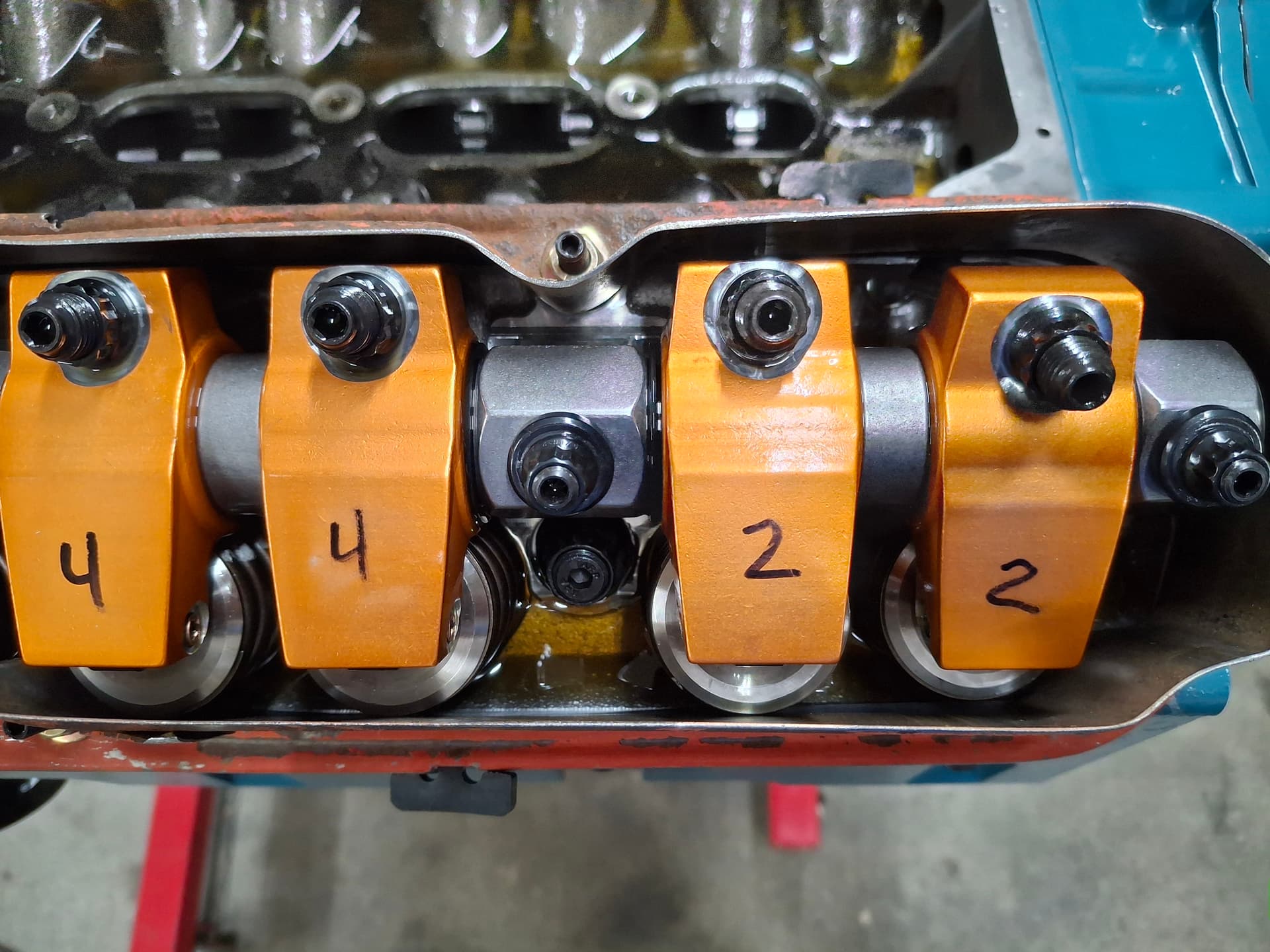
Valve Adjustment
The camshaft calls for 0.022" hot lash, so I set cold lash at 0.014" (cold spec is 0.06" - 0.08" tighter than hot spec for iron block with aluminum heads) and will adjust them again when the engine is hot. I’m in the habit of writing the cylinder number on the rocker arm that has been adjusted, hence the writing in the photos. I’ll point out that an assembled engine with 560 lbs. of open spring pressure with 0.640" lift is considerably harder to turn over by hand with a 12" ratchet than just the rotating assembly without heads–even with the spark plugs out. I imagine turning it over by hand with 11:1 compression and spark plugs installed will be close to impossible without a very long breaker bar. Hopefully my high-torque starter motor and battery are up to the task ![]()
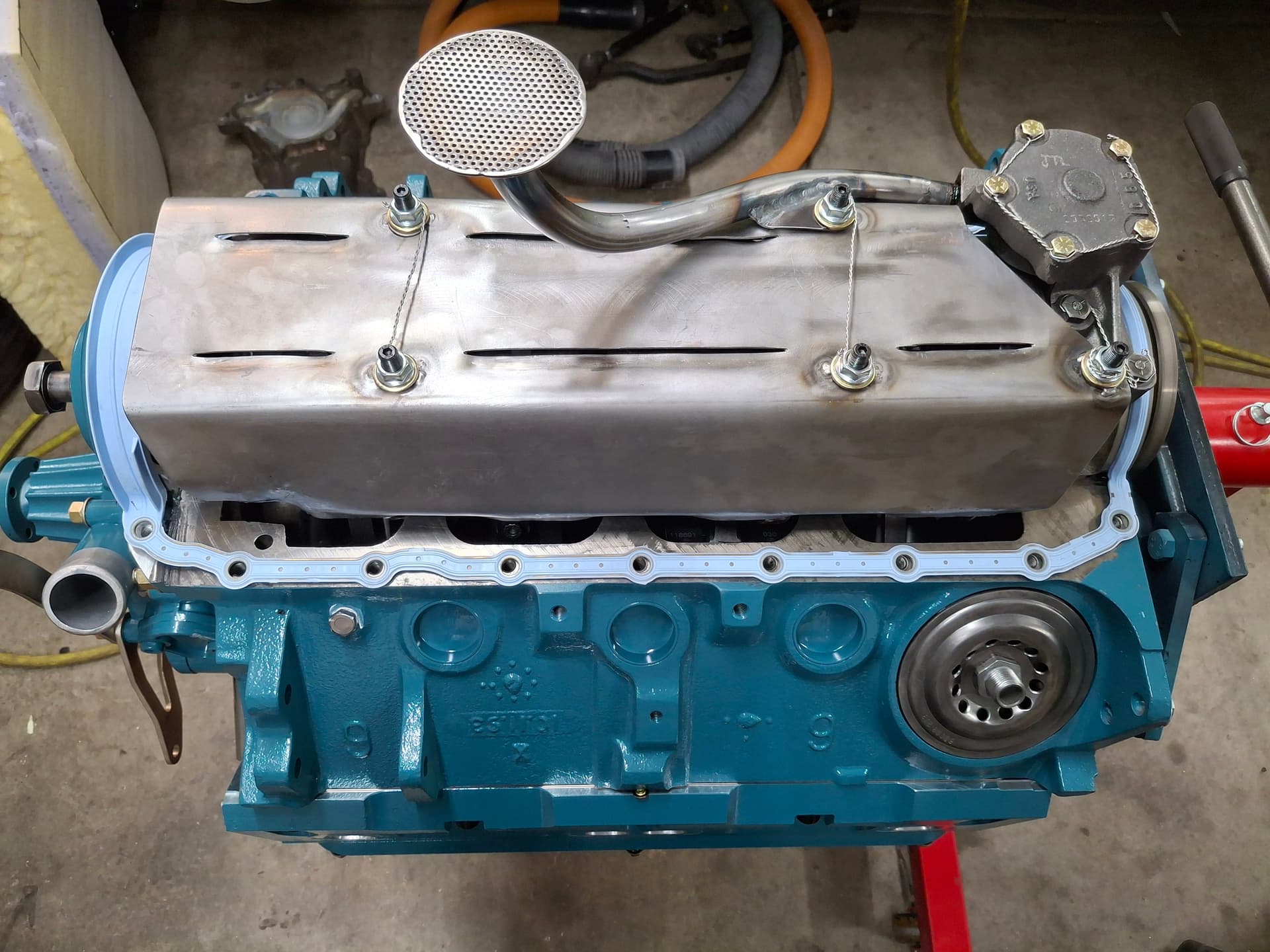
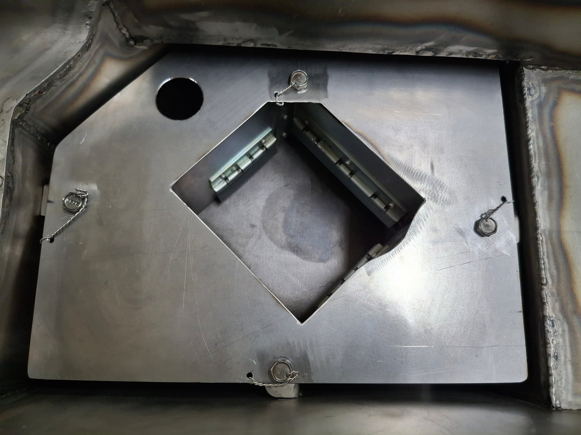
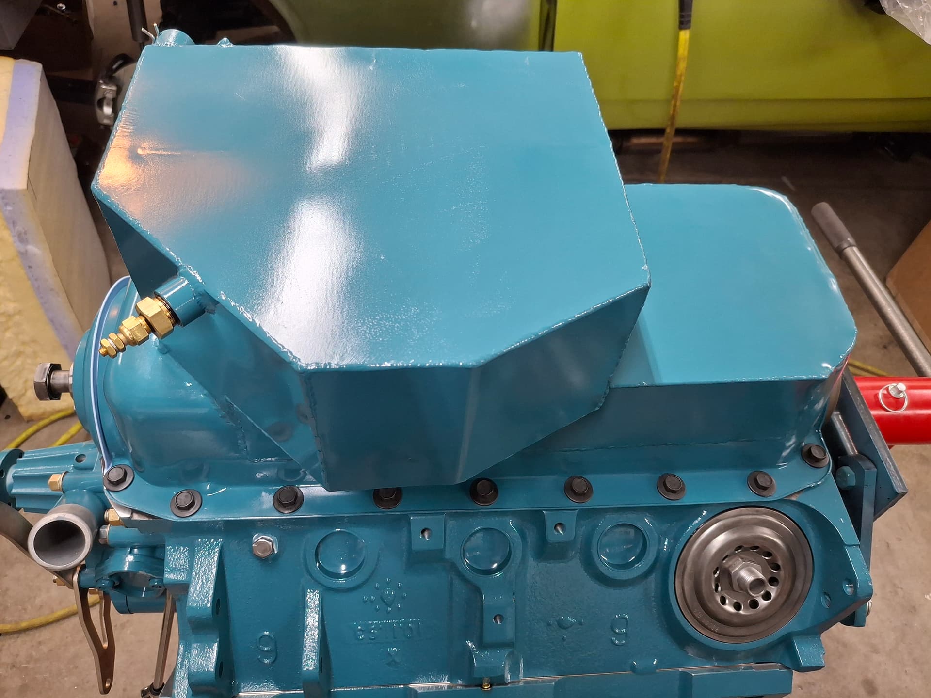
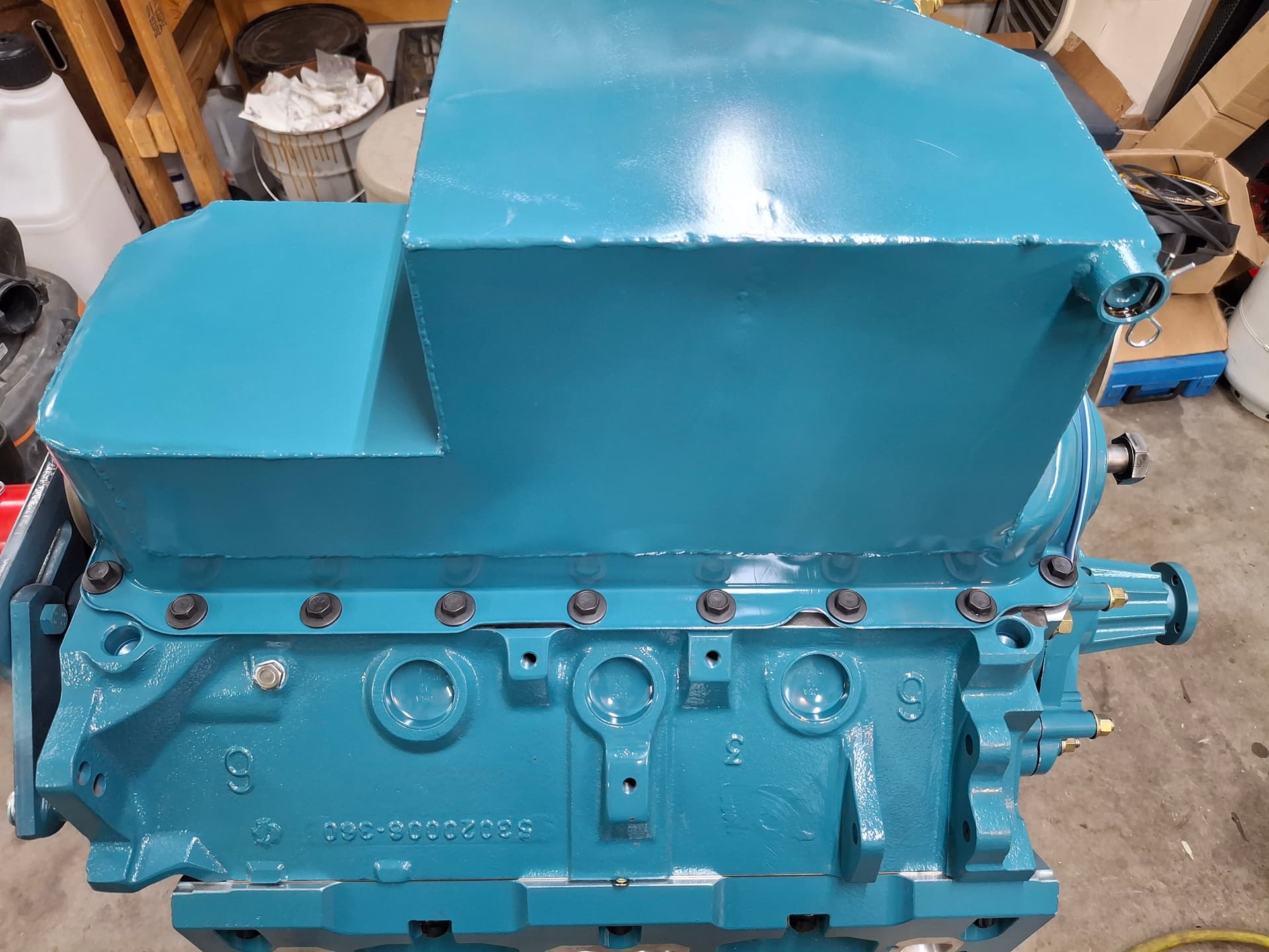
Oil Priming
I like to prime the oiling system with the intake off so I can inspect all the lifters and listen to the sump for any issues with sucking air. Mopar heads don’t have high sides to stop pooling oil from overflowing, so I cut the tops off of the factory stamped steel valve covers and cleaned them well to make an oil dam. With them installed, I poured in 7 quarts of Valvoline VR1 10W30 racing oil and filled the new oil filter I’m using for the dyno, installed the hex priming drive shaft down into the pump, and installed my test oil gauge. A 1/2" 900 RPM Milwaukee corded drill did the heavy lifting at the equivalent of 1,800 crank RPM. I was happy to see the oil pressure immediately jump to 58 psi and maintain at least 22 psi with the drill at the lowest RPM (RPM unknown, but I assume lower than idle RPM). The pain with small-block Mopars is that the rocker arm assemblies aren’t constant oiled but get a spurt of oil when the camshaft oil gallery aligns with the head gallery every full rotation of the camshaft. The right head gets oiled on one crank rotation (1/2 of the camshaft rotation), and the left head gets oiled on the second crank rotation from a different cam bearing journal. When the engine is running, this pulsing is undetectable with the oil stream practically constant, but priming the system by hand either requires putting a degree wheel on the harmonic damper and turning the crank to the specific alignment locations (105 and 120 degrees AFTDC for those curious) or slowly turning the crank by hand until you see oil ooze out of a rocker-arm assembly. If I had help, I would have simply had that person keep the drill going while I smoothly rotate the crank until oil start flowing, but I didn’t. Instead, I turned the crank 10 degrees, ran and stopped the drill, turned the crank, ran the drill, back and forth until I found both the alignment sweet spots for each head. I was happy to see ample oiling for each head but not excessive oiling, which can be an issue with Mopars taking oil volume and pressure from the crank mains.
The roller lifters also got an insane amount of oil, which I didn’t expect. These are my first high-dollar Mopar solid roller lifters, so I was expecting more of the dribbling seen in flat-tappets and cheaper hydraulic rollers. However, these roller lifters have direct oiling from the block lifter gallery down to the roller tip, which translates to a constant heavy stream of oil gushing out of the lifter body, over the roller tip, and over the cam lobe. It looks great for oiling, but maybe not for oil pressure. We’ll see where hot pressures are at at idle and 7,000 RPM, but hopefully I don’t have low oil pressure when bringing in the oil cooler system. I might need to bump up to 20W50 or, worst case, pull the oil pan and pump, remove the pressure relief valve in the pump, and either shim the spring or install a high-pressure spring (I kept the standard pressure spring in the high-volume pump and shimmed it with one washer for a little higher pressure). At 58 psi cold at 1,800 RMP, I’m optimistic my hot pressure at 7,000 RPM will be above 55 psi.
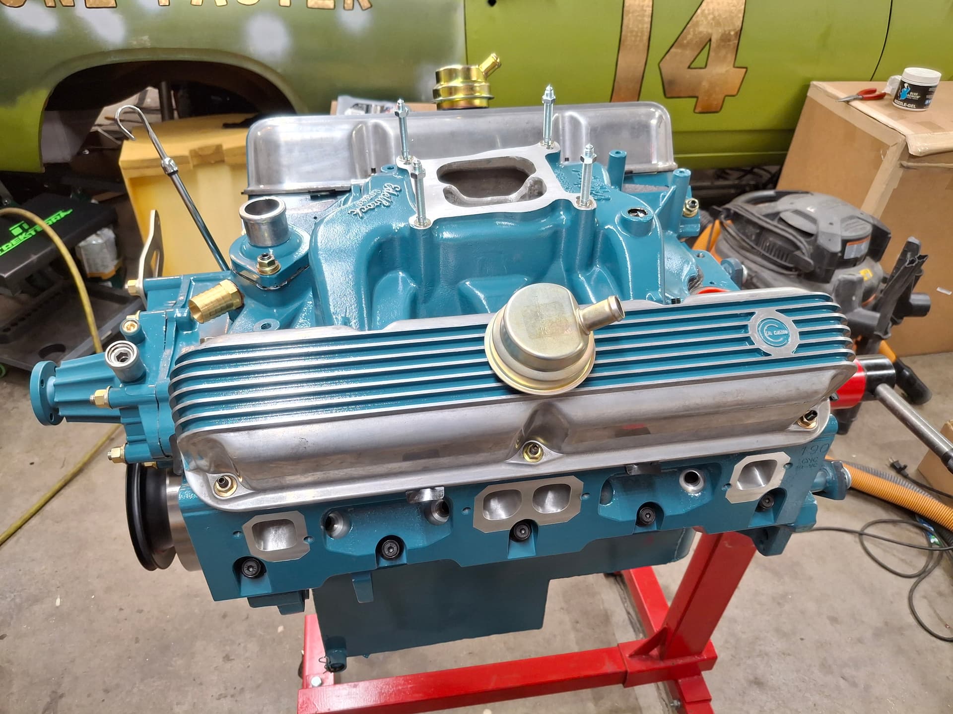
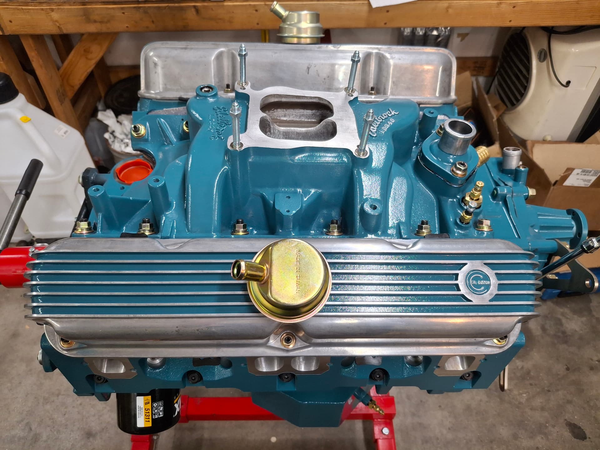
Intake Manifold and Valve Covers
With oil priming complete and gasket surfaces cleaned, I installed the intake manifold using the four 1/8" holes I drilled through the intake, gasket, and into the heads to align the gaskets on both the heads and intake runners. Rather than using bolts in the aluminum heads, I installed 3/8" alloy studs, washers, and lock washers to get a solid torque that hopefully won’t loosen as easily under race conditions. The 1960’s Cal Custom valve covers received one-piece rubber gaskets before I torqued them down. I’m going to try the rubber gaskets first as a reusable option since I’ll be checking the valves more often, but I may bring a set of cork gaskets to Pete’s shop when we dyno the engine just in case the rubber gaskets leak. I’ve never used the rubber gaskets on a Mopar before, so I don’t know how they’ll act.
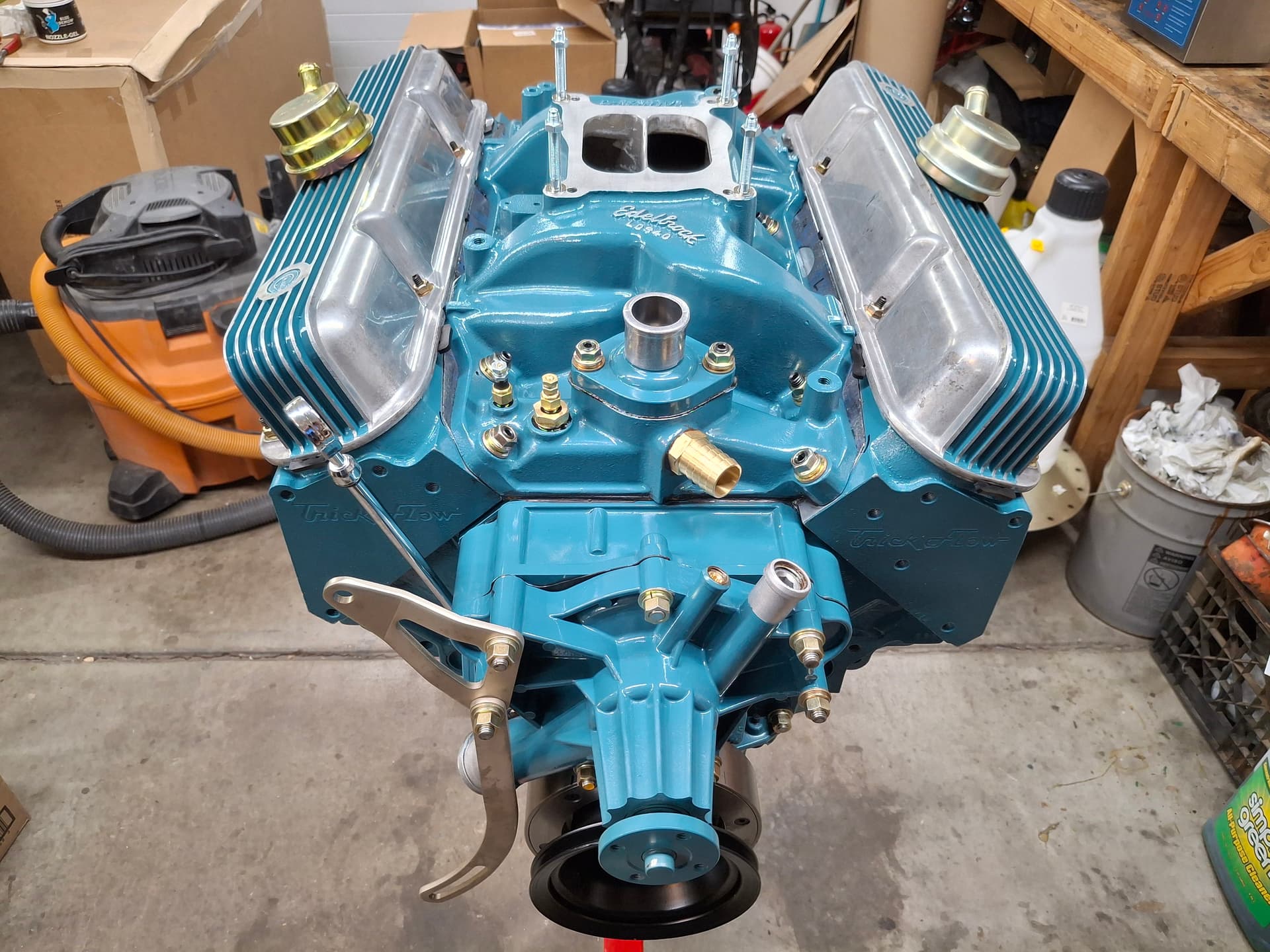
Aside from spark plugs, which I’m tackling tomorrow, the engine is finished and ready for the dyno! There are multiple devils in the thing, so hopefully they all work with me versus against me. Time will tell, and hopefully we’ll have it on the dyno in the next few weeks.
Post Alert:
@jonUU
@Sportsracer
@Datsun78
@Bob_Alder
@Rich
@Nick_H
@jackson_prime101
Damn nice & pretty work!!!
1 Like
Looking good Justin. Wishing you a great payoff for your hard work and attention to the small stuff.
1 Like
Those valve covers are gorgeous.
1 Like
Thanks everyone for the kind words! It was nice seeing some of you at Pueblo over the weekend for a great race.
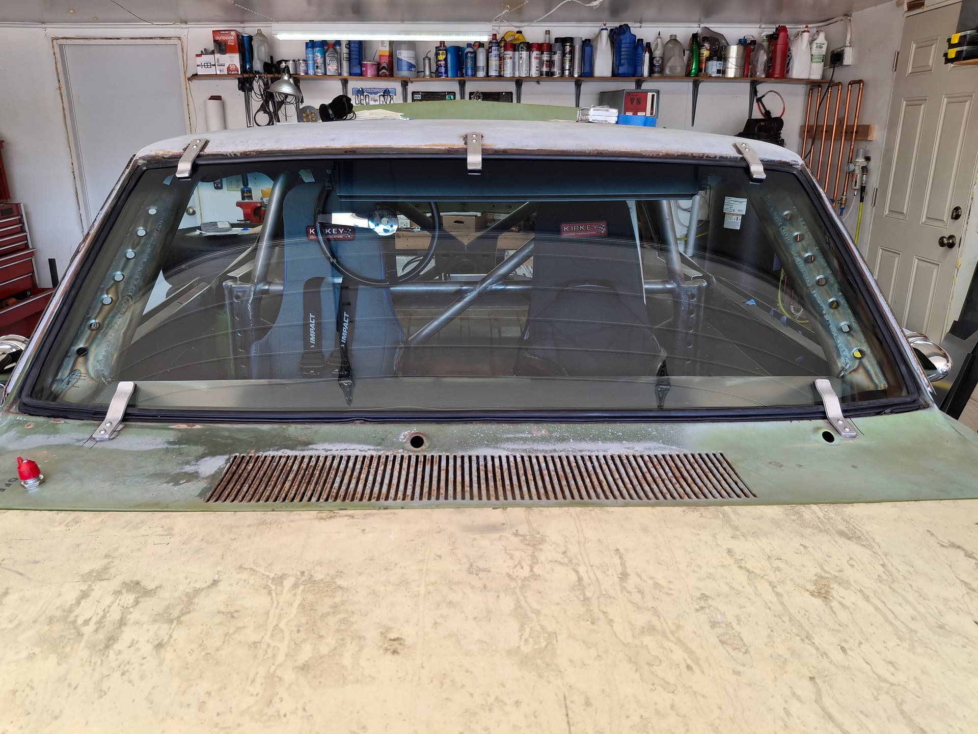
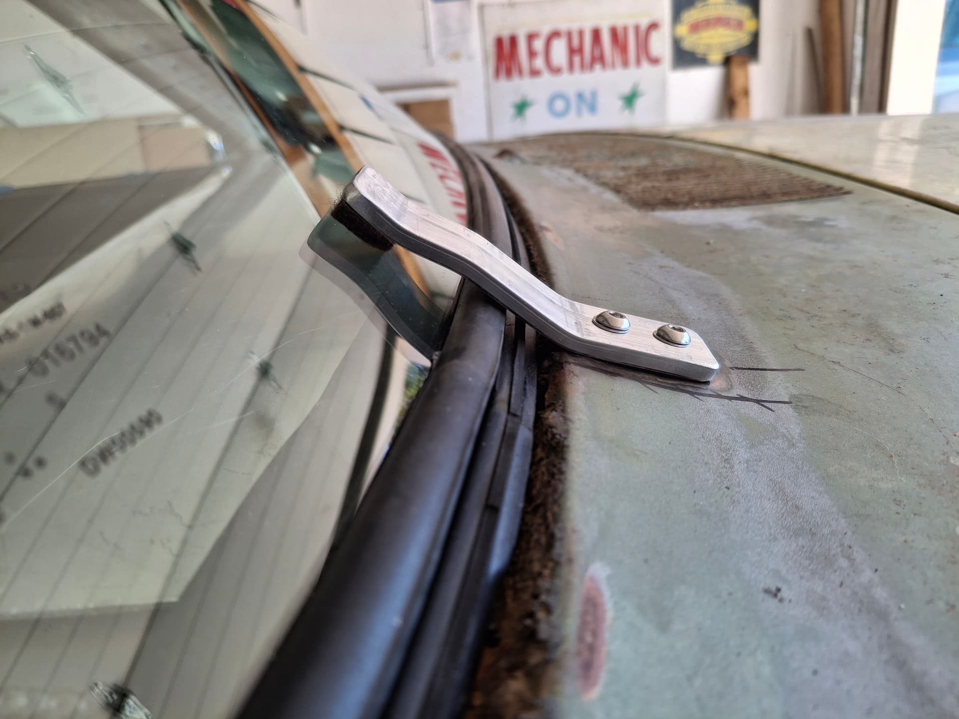
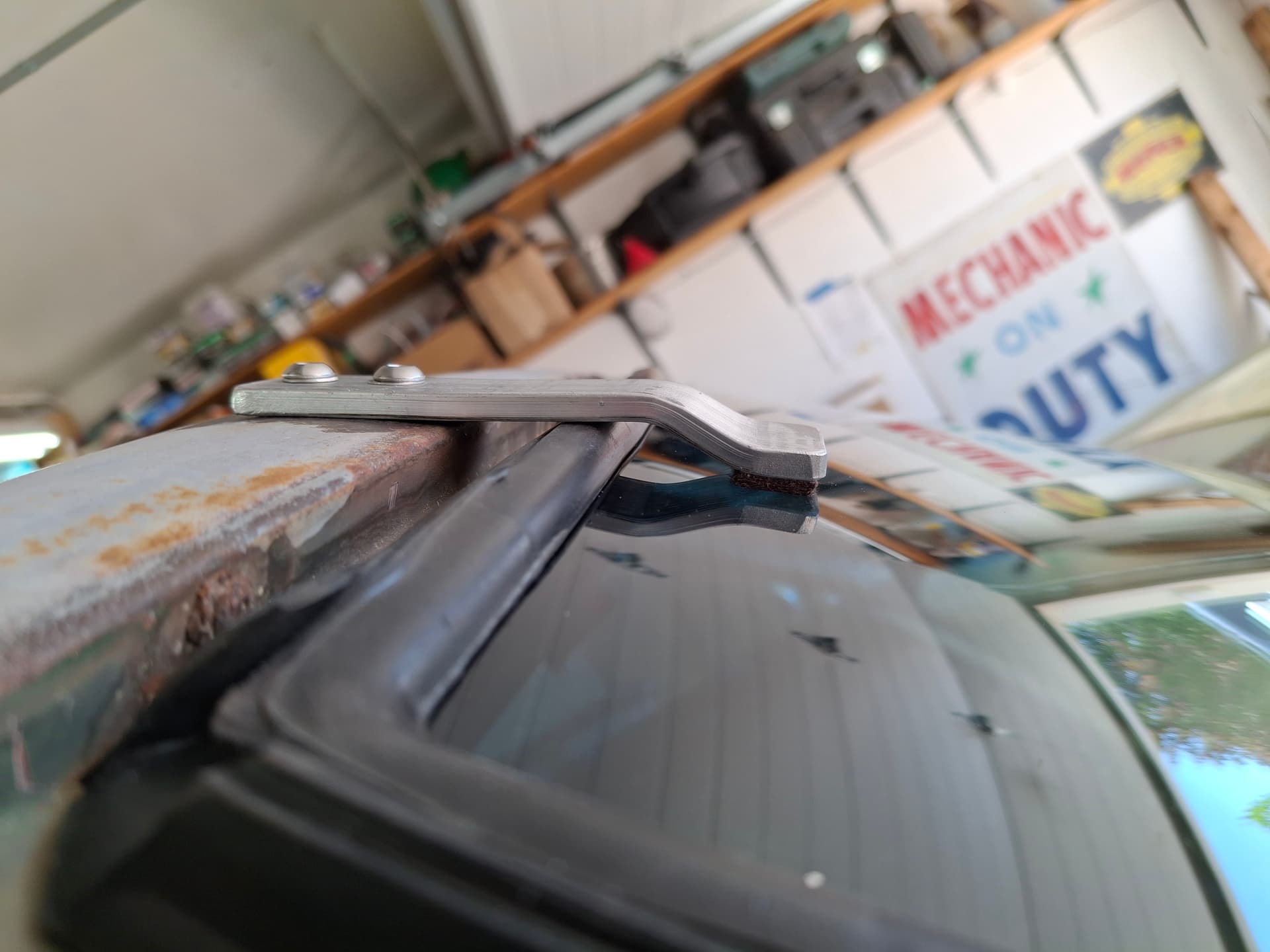
Windshield
The new windshield and seal arrived, and I got it pulled into place with the normal amount of struggle for such things. I built the retaining clips from 1" x 3/16" aluminum bar including felt pads.
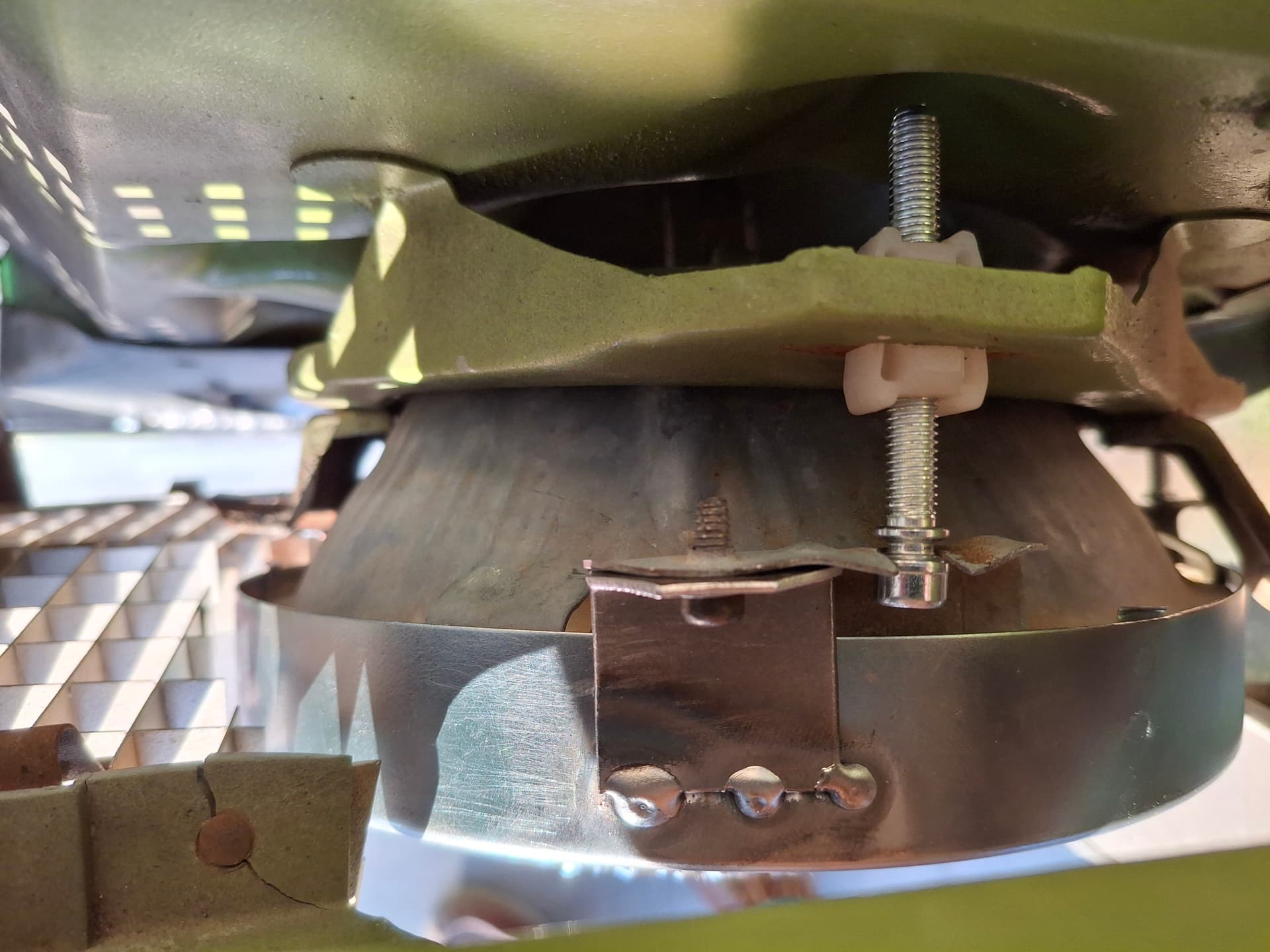
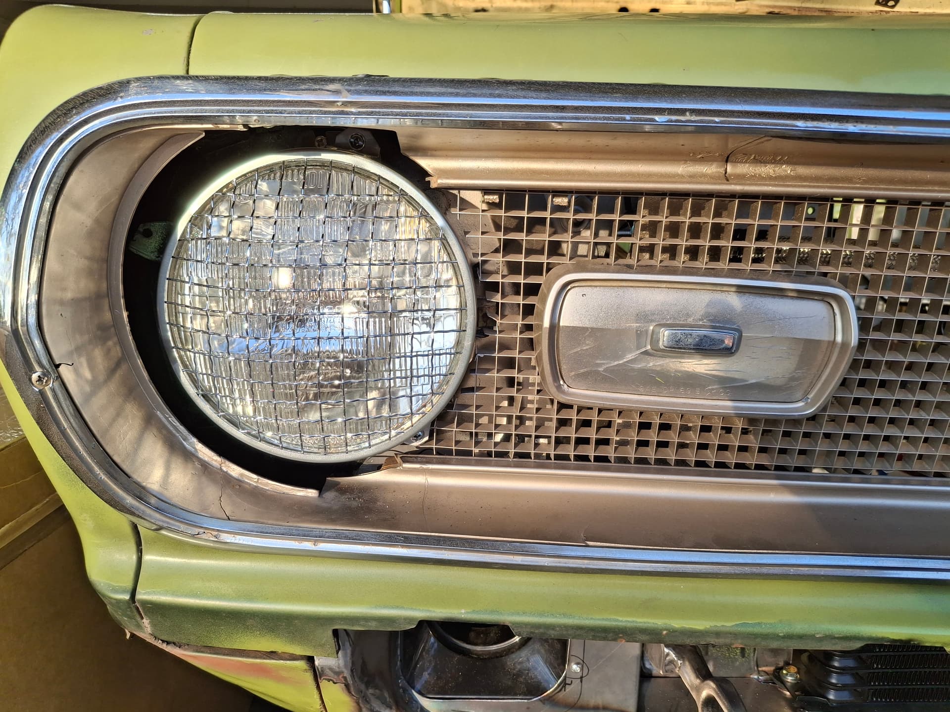
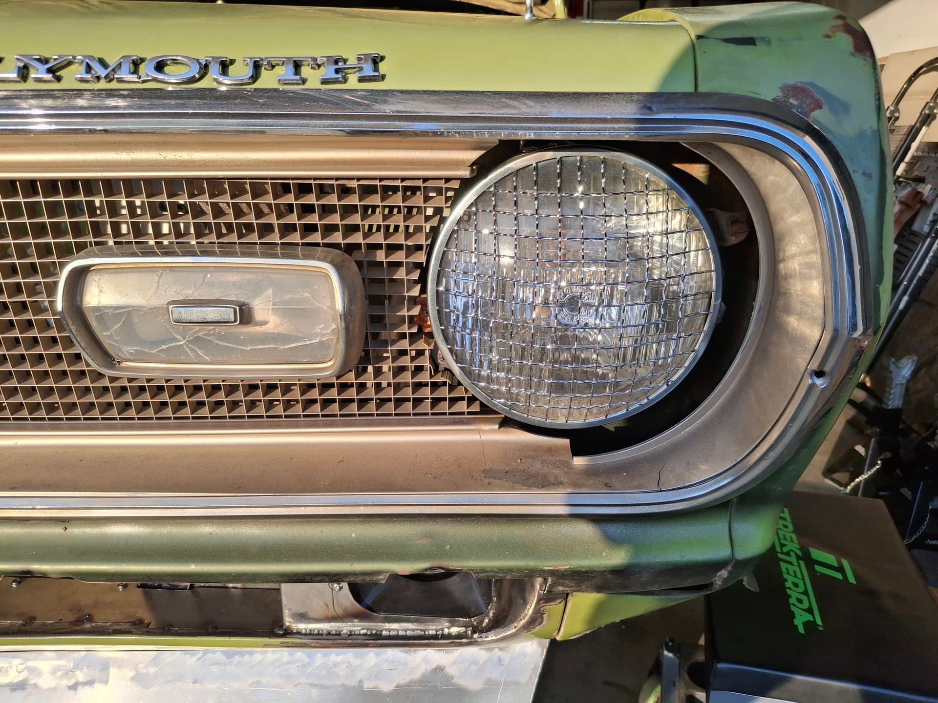
Headlight Grilles
I obtained some chrome headlight grilles, but the factory headlight retaining rings were too shallow to hold both them and the headlights in place. I settled on a new pair of 1970’s GM headlight retaining rings that were the deepest I could find, but the mounting tabs were now the incorrect bolt pattern. I cut off the old ones, belt and drilled new ones, and welded them to the new retaining rings. The next issue was that the adjuster screw plastic inserts were cracked beyond use and the adjuster springs holding one side of the headlights in place missing, and the left headlight bucket was rotted through from packed mud and fell apart in pieces when I removed that headlight. I was lucky to obtain a pair of good headlight buckets from a Mopar forum and new adjuster hardware/springs, and everything then came together. Keep in mind that the car wiring no longer has a provision for headlights, but I wanted to maintain the look of headlights versus fabricating block-off plates. The plastic headlight bezels aren’t yet installed in the photos:
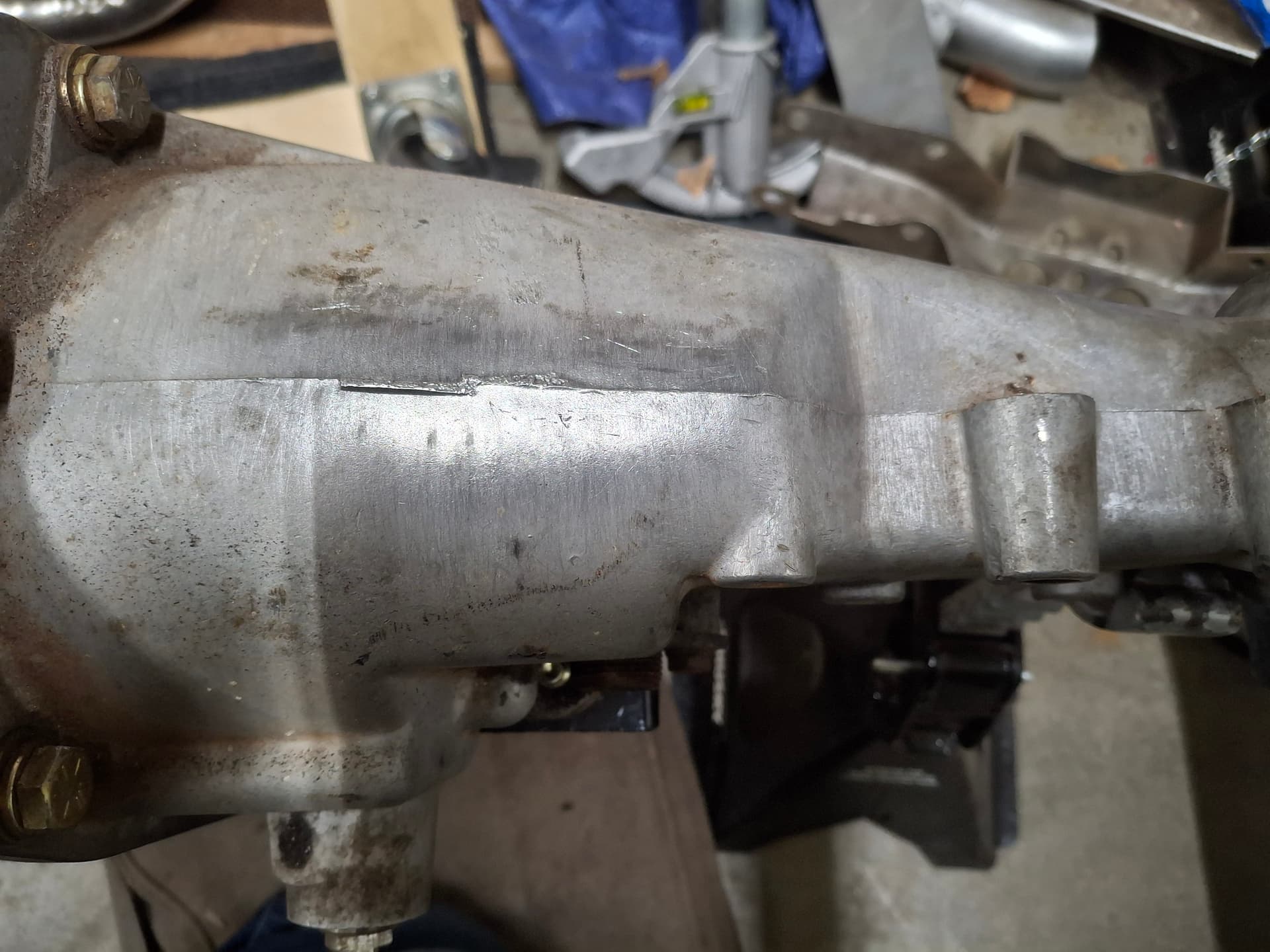
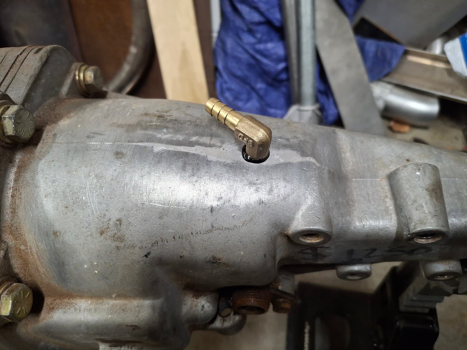
Transmission Vent
Per RMVR’s General Rules, the transmission requires a mesh breather or extended/looped tube breather, but the factory GM Muncie transmission uses a simple breather in the front bearing retainer that theoretically can leak without containment in the event of pressure buildup, which would be highly unlikely. Still, to address the rule, with plenty of grease to catch the shavings and with the transmission upside down, I drilled and tapped a hole in the top of the tail housing to 1/8" NPT and installed a barbed elbow. 1/4" hydraulic hose will go from this elbow up to one of the engine oil catch cans in the engine compartment.
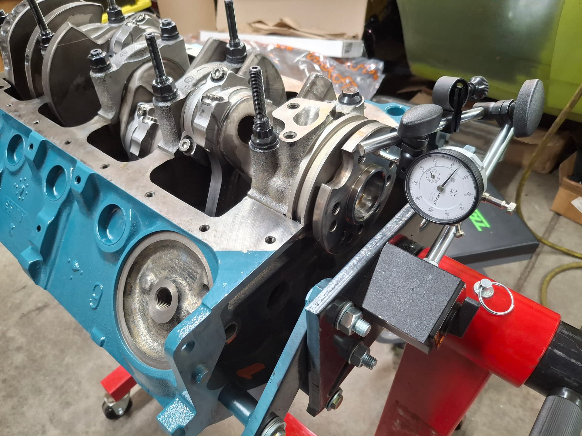
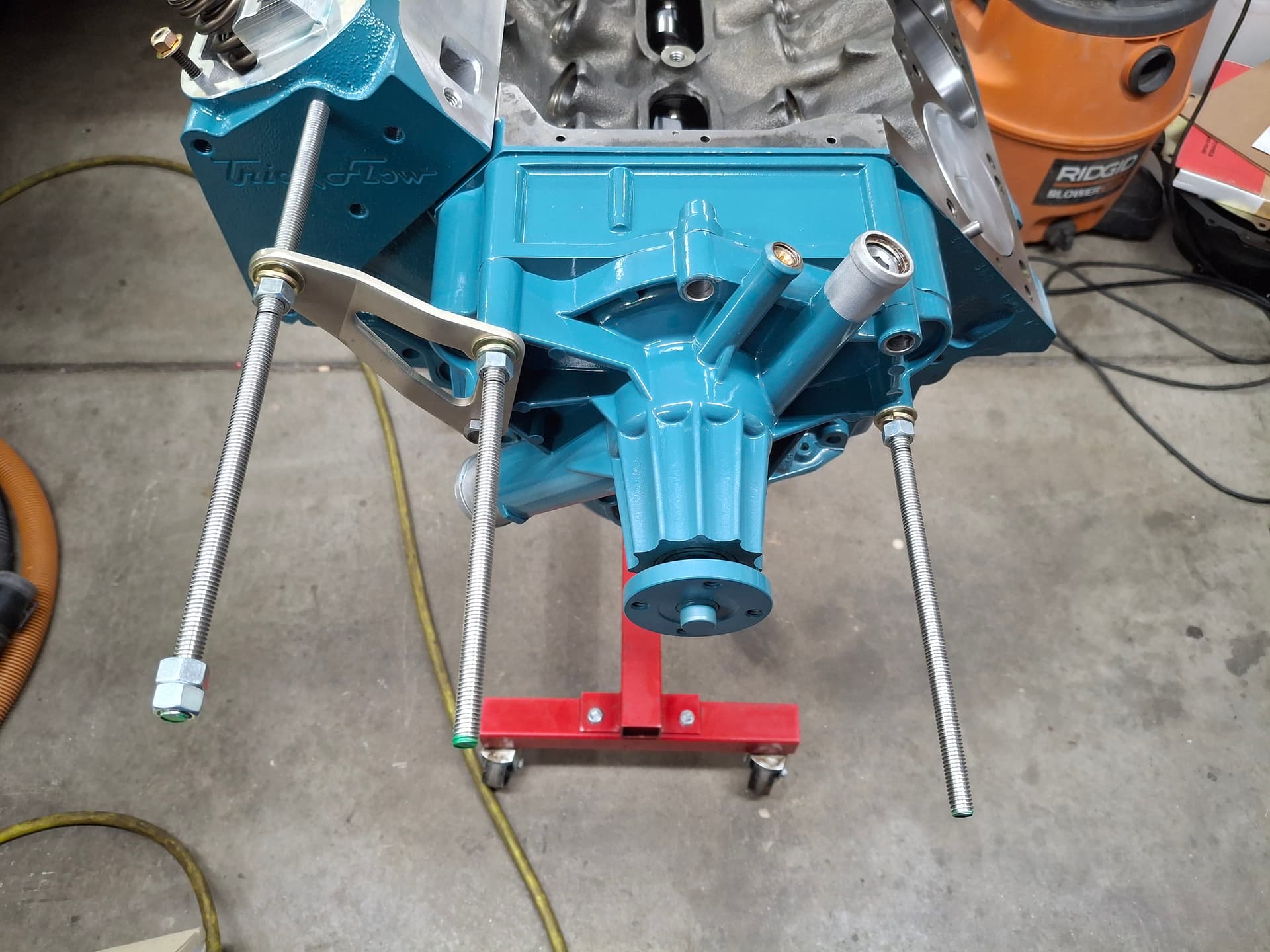
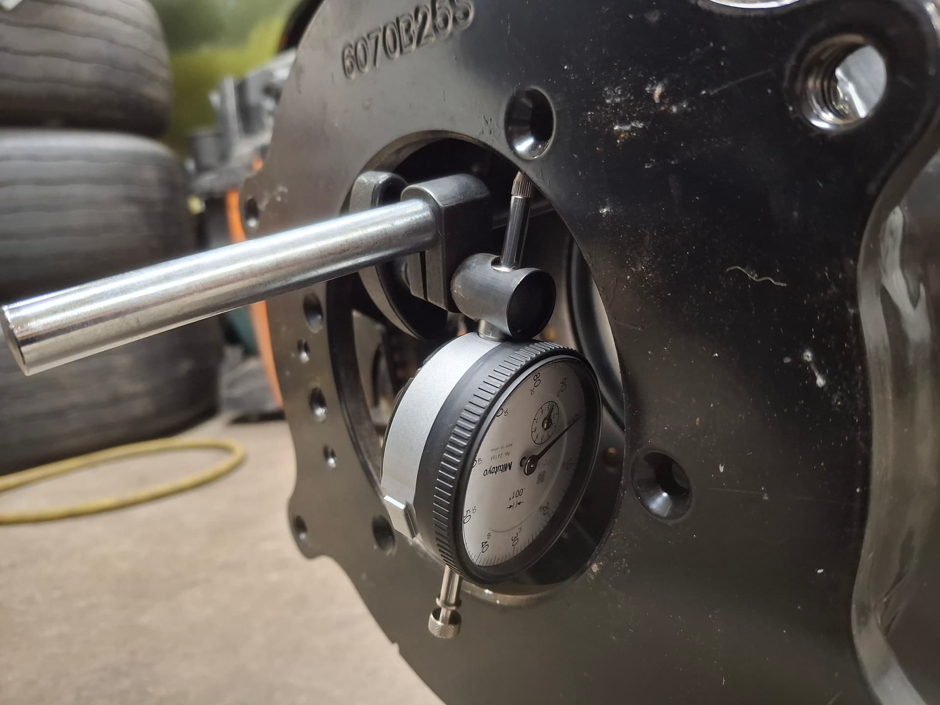
Bellhousing/Scattershield Runout
With the engine now on a transportation stand I welded up, I drove in a new input shaft bushing, bolted on the scattershield, set up a dial indicator, and turned the crank 360° to measure the runout. The GM Muncie spec calls for no more than 0.005" runout, although my understanding is that the input shaft bearings are forgiving enough to handle closer to 0.012". The scattershield came in at 0.002" runout, so I was relieved that I wouldn’t need to drive out the bellhousing alignment pins and purchase/install offset pins.
Post Alert:
@jonUU
@Sportsracer
@Datsun78
@Bob_Alder
@Rich
@Nick_H
@jackson_prime101
I’m catching up on some updates that I realize I never posted.
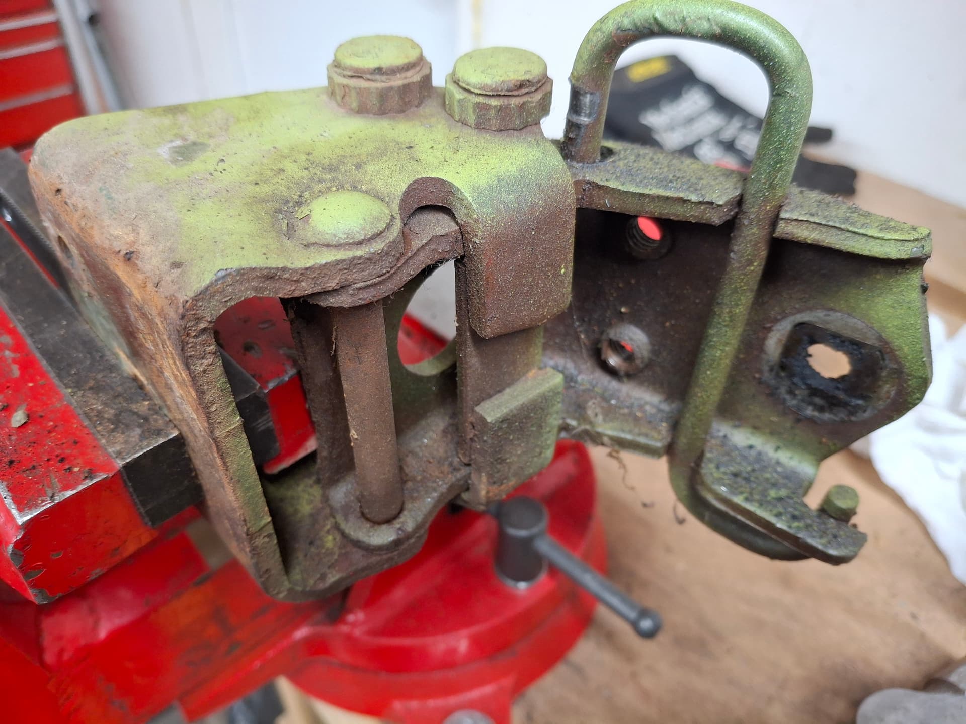
Door Hinges
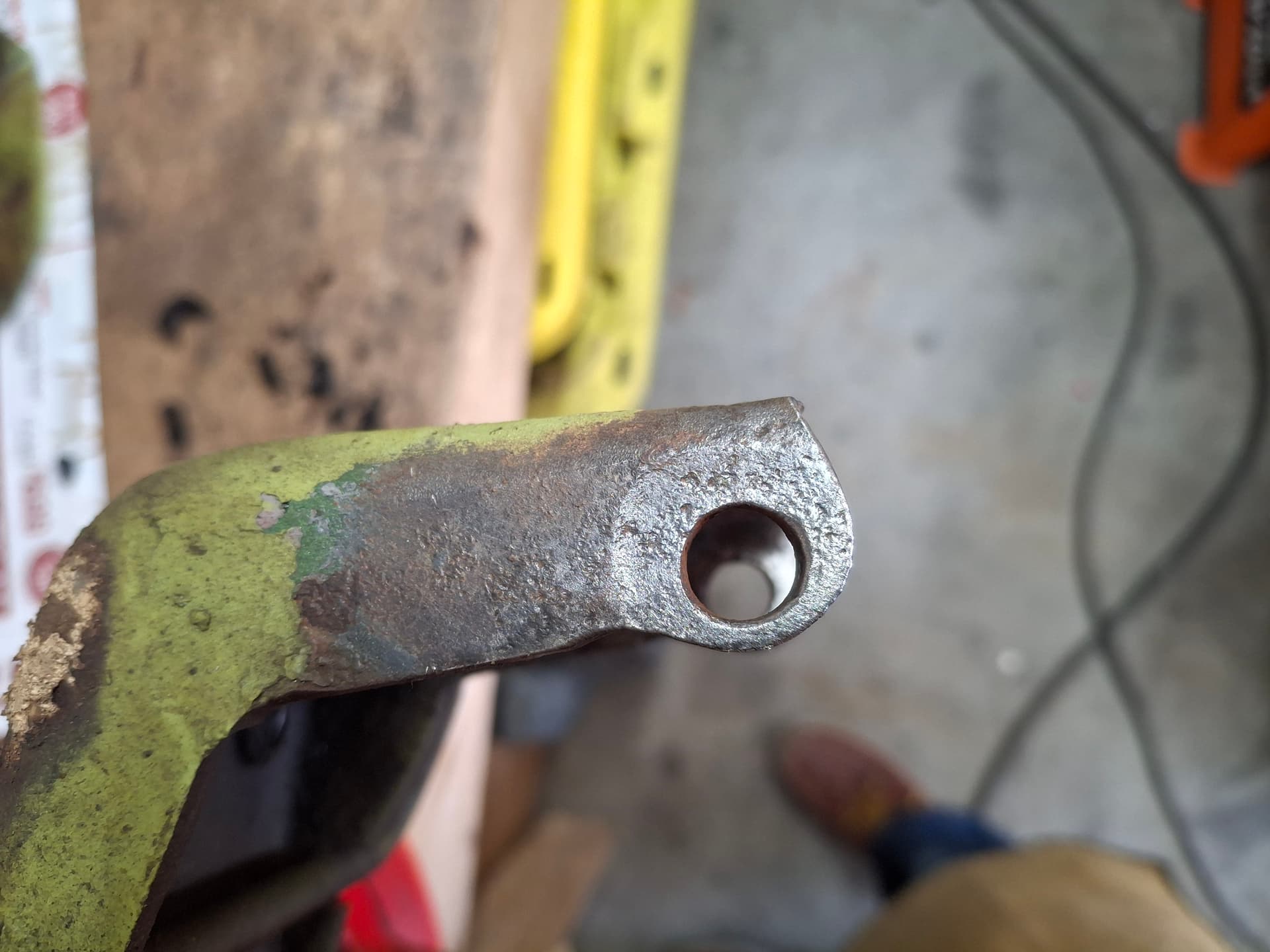
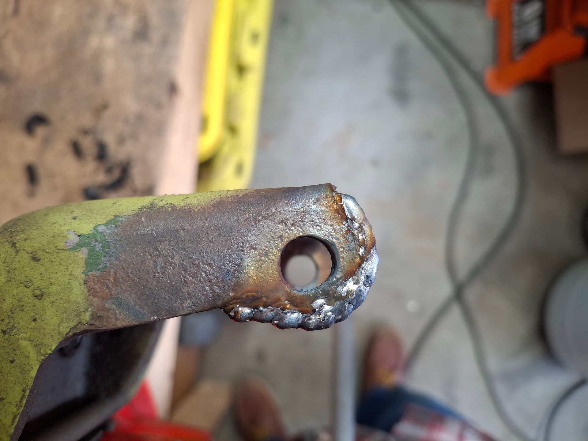
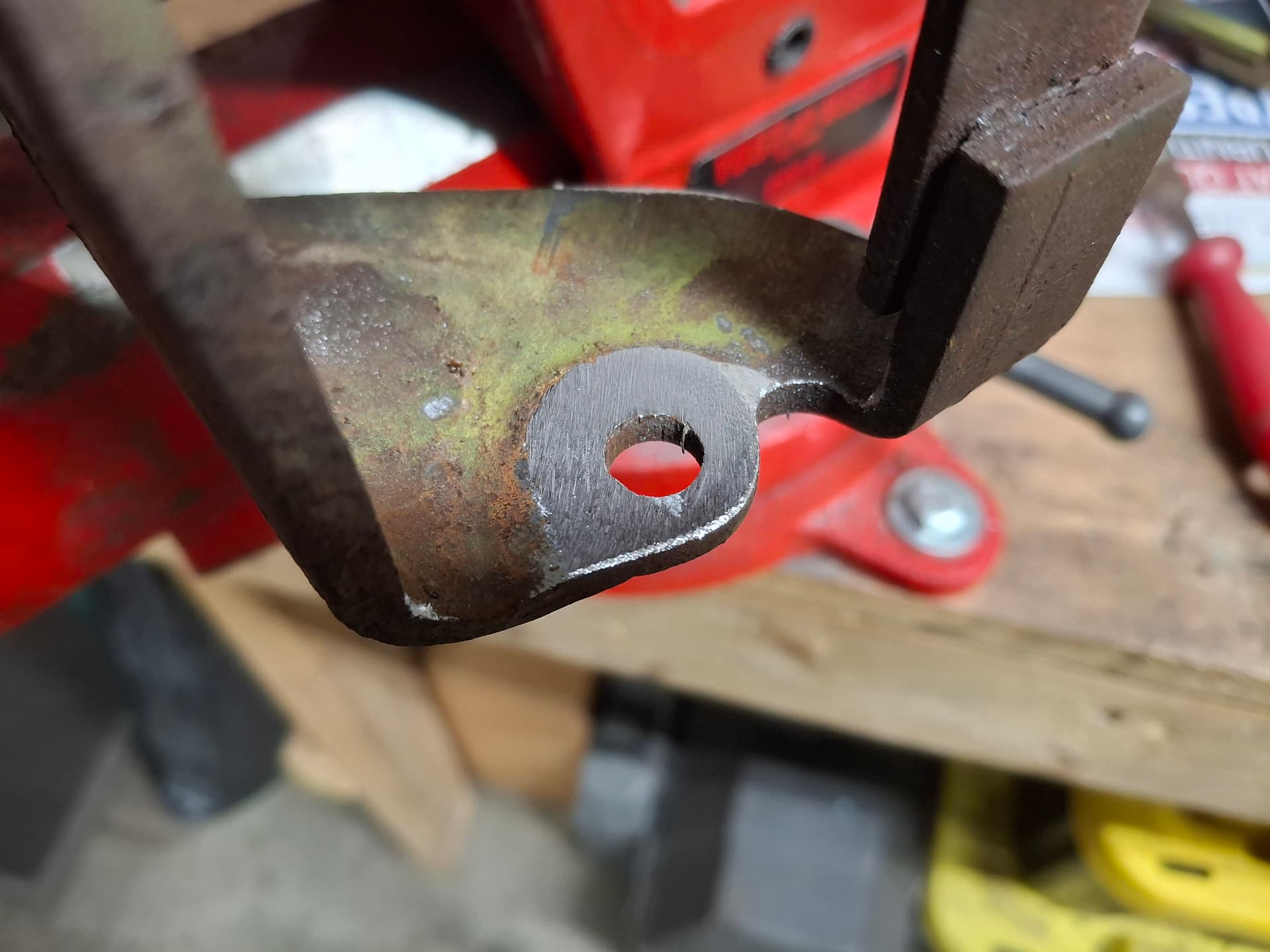
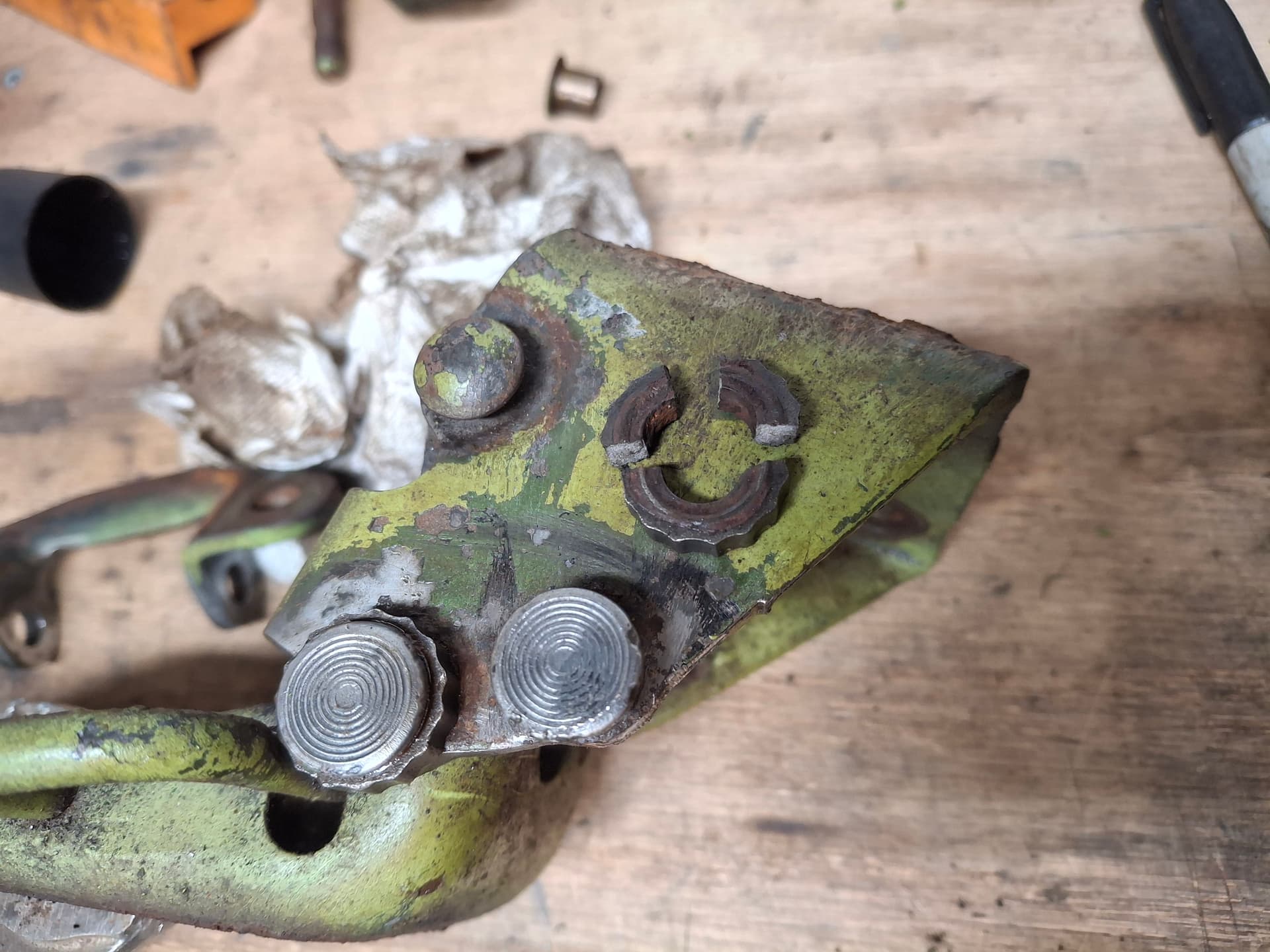
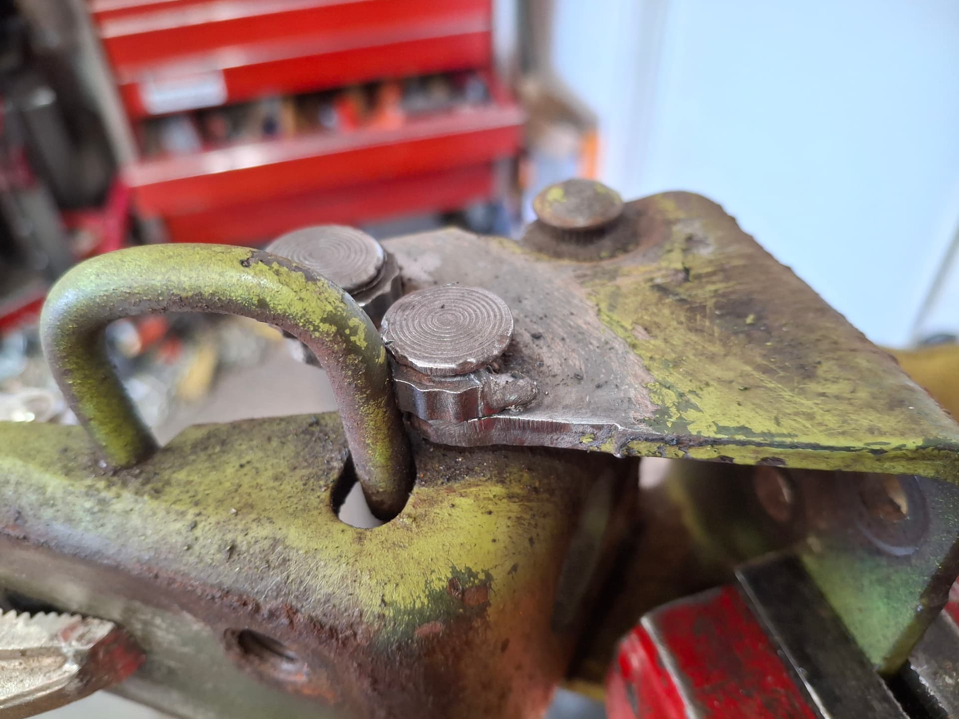
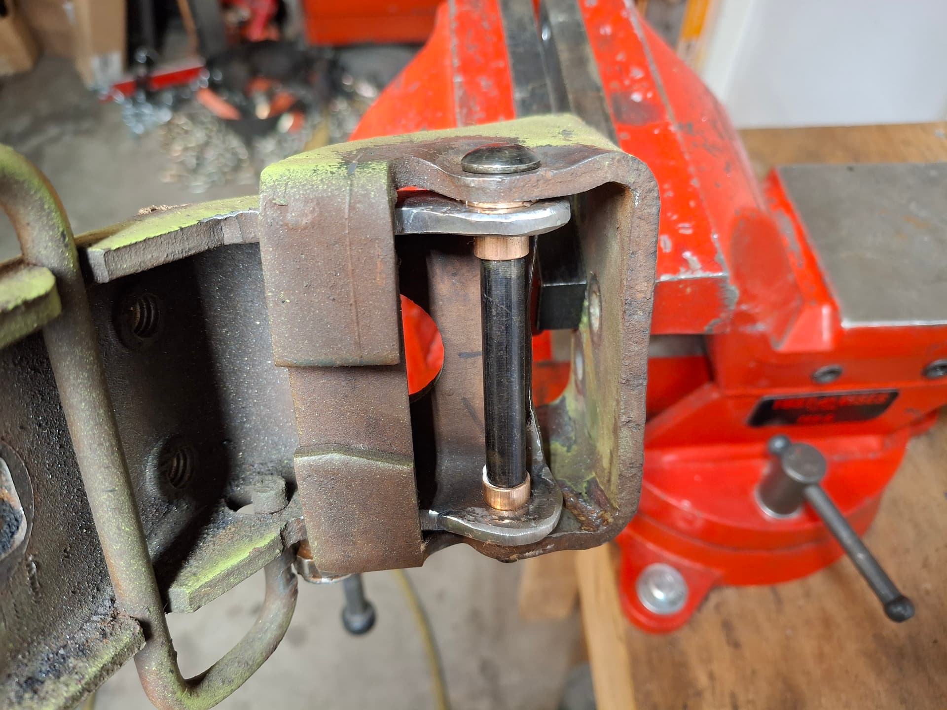
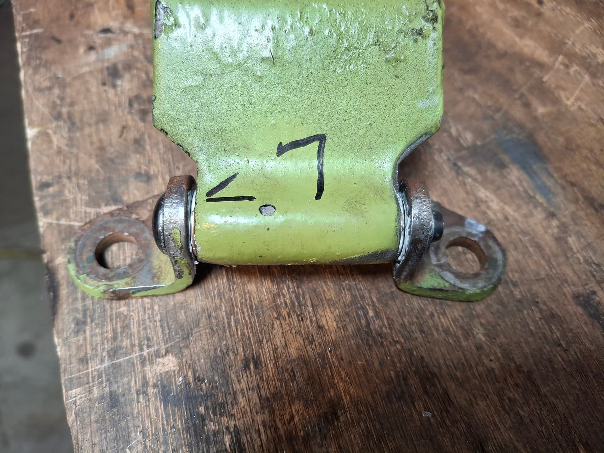
The original door hinges were badly, badly worn allowing me to pull/push the door up and down 1". Aftermarket replacements can be had for $200 for both doors, or a GM pin and bushing rebuild kit can had for $10, but it requires drilling out the inner bottom hinges and grinding down the outer bottom hinge to accept the GM bronze bushing, reducing the strength of the hinge. However, the hinges were so badly worn that these holes were already hogged out and would require welding up and re-drilling, so I opted for the GM pin/bushing kit and got to work. Keep in mind that I will eventually media blast the hinges when I do the final bodywork, so I focused only on mechanically rebuilding them and not paint.
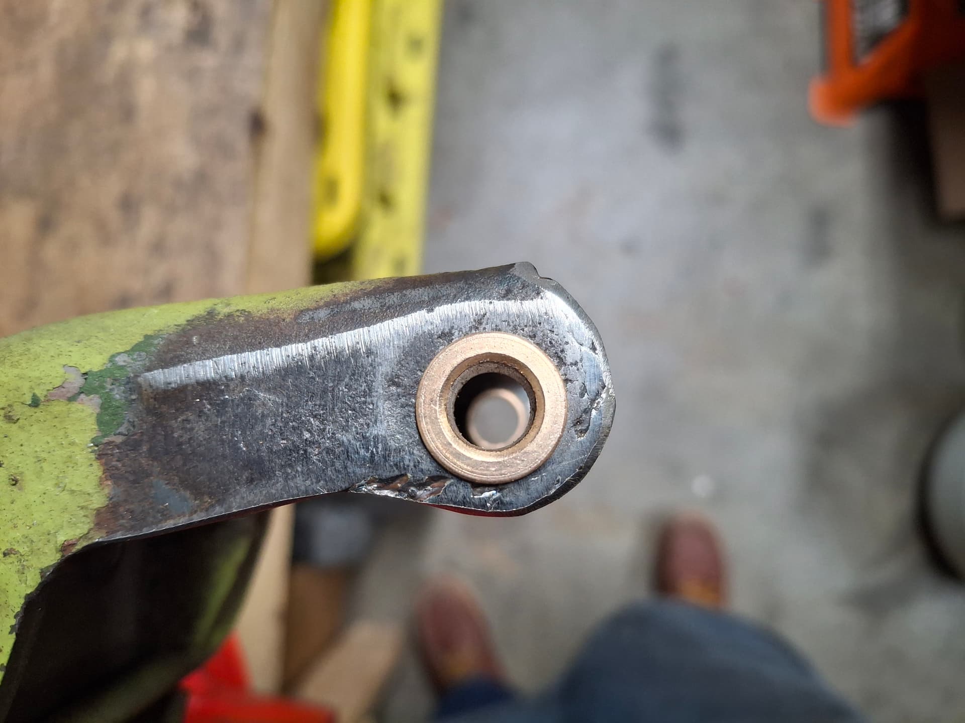
After disassembling the hinges, I welded additional material to the ears to add back the material the bushing would rob, ground everything smooth, and drilled new holes. With the bushing pressed in, I ground and then filed the outer hinge for a snug fit against the bushings. New pressed pins made for a tight joint. The top hinges got new bushings a pins.
The four serrated door-catch rollers were badly seized and took a day of soaking with penetrating oil and torch heat to loosen, but the full-open catch on the right/passenger hinge shattered when I was twisting it with pliers. They aren’t reproducer, and it’s a race car, so I welded one half in place. The catch spring doesn’t roll as smoothly, requiring a little more force to open/close the door from the wide-open position, but it gets the job done just fine.
With the rebuild hinges installed, the doors align nicely with no slop.
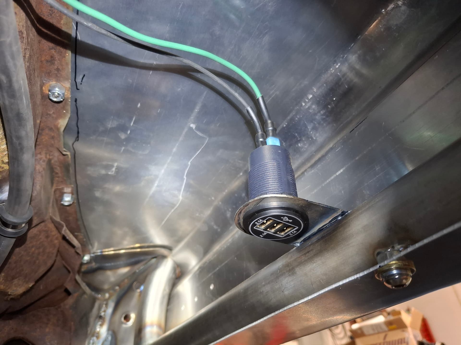
Dash Electrical USB Port
Anticipating eventually installing a system like a Garmin Catalyst, welded a bracket onto the roll-cage dash crossmember and installed a USB power port.
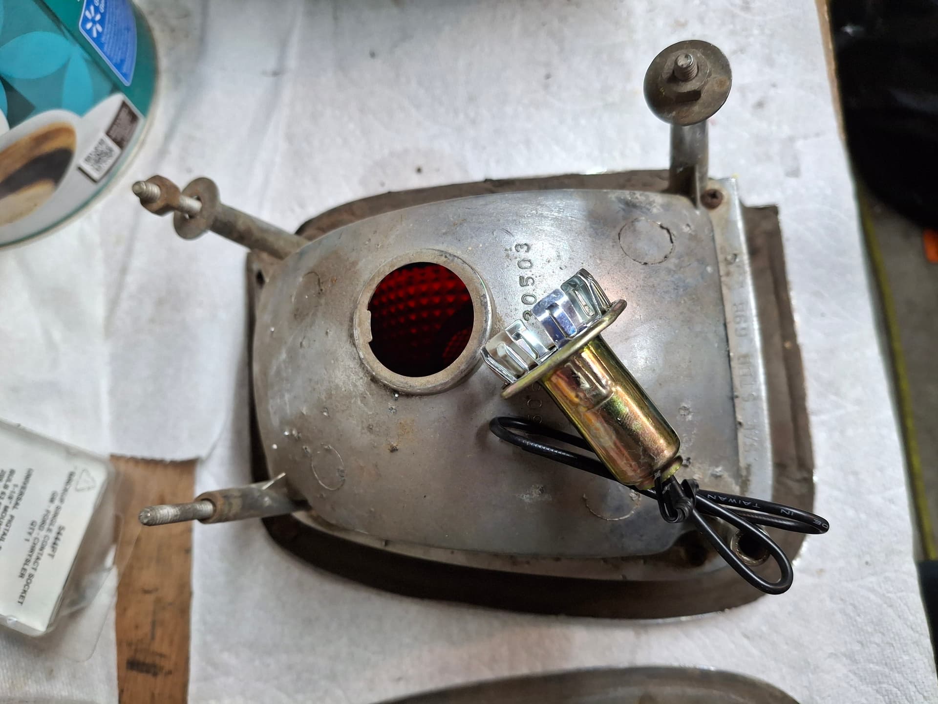
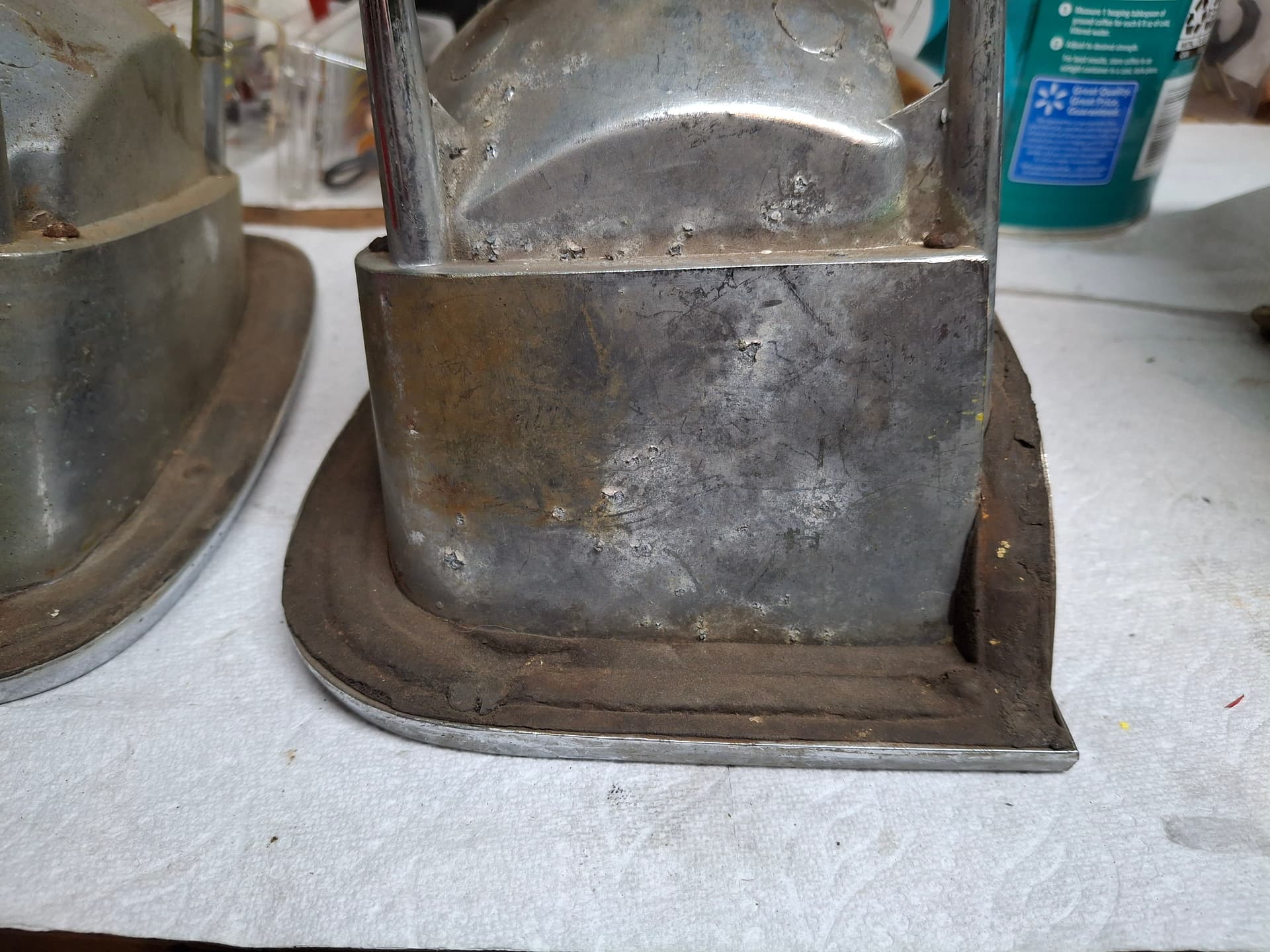
Tail Lights
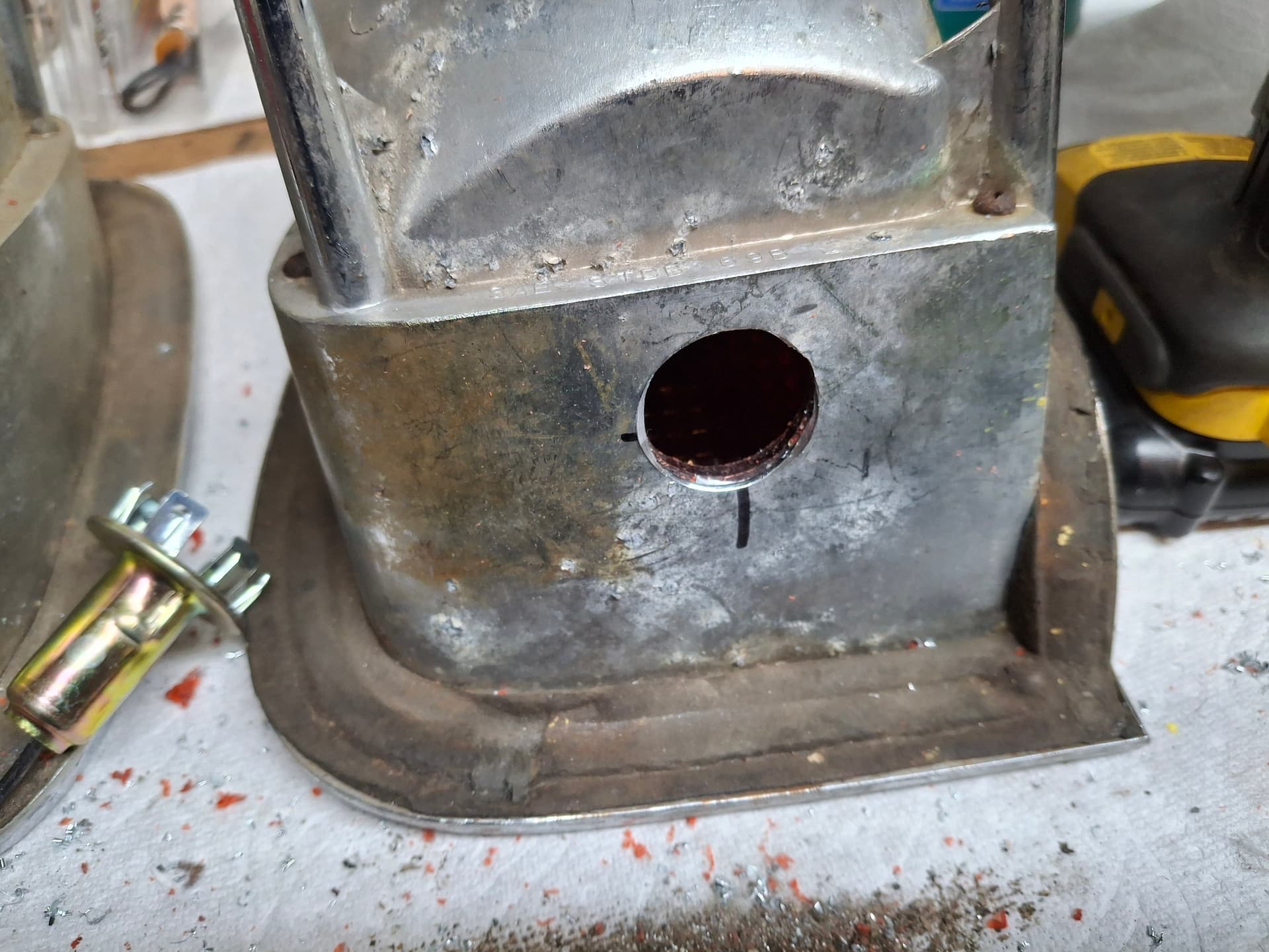
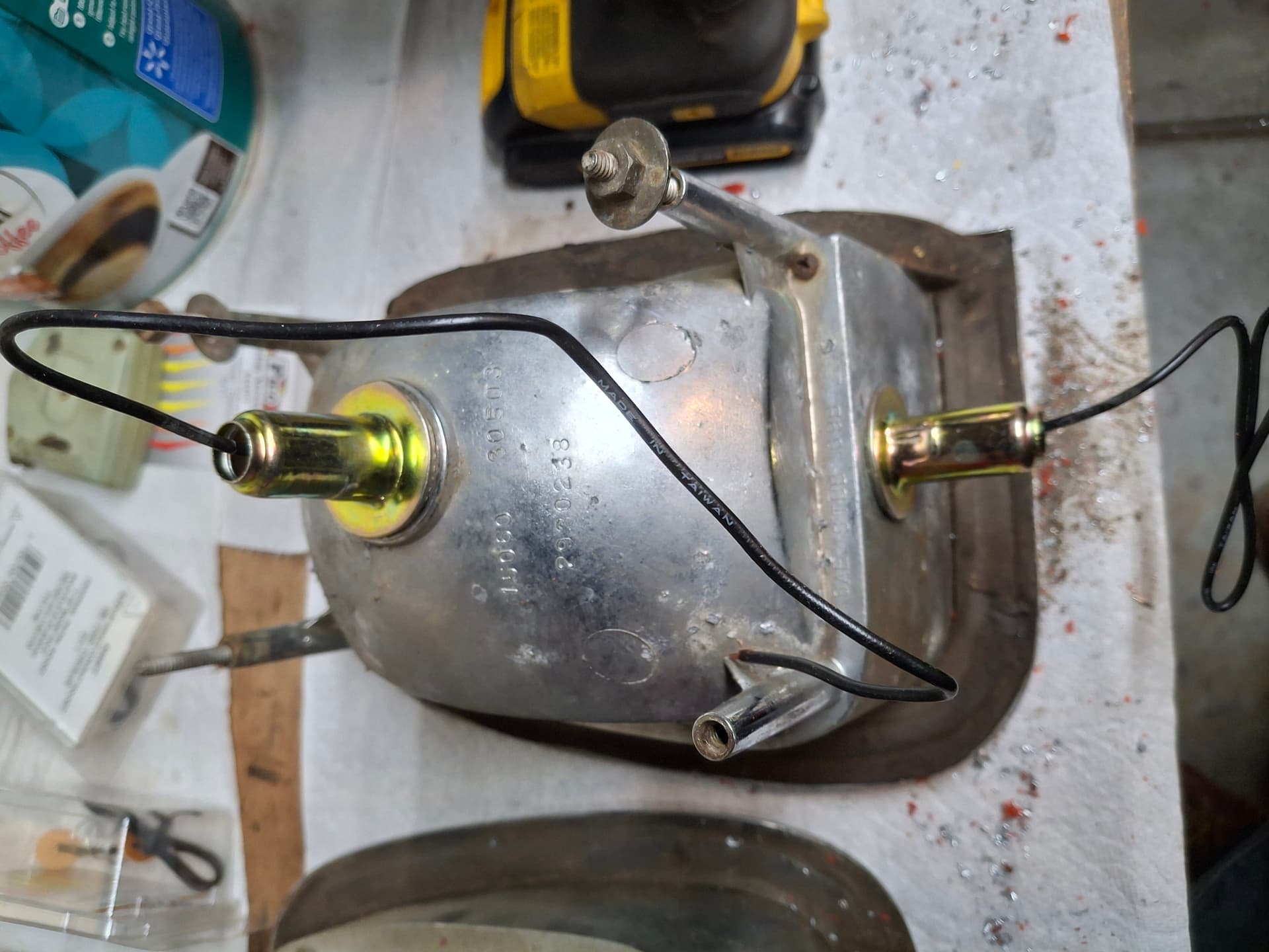
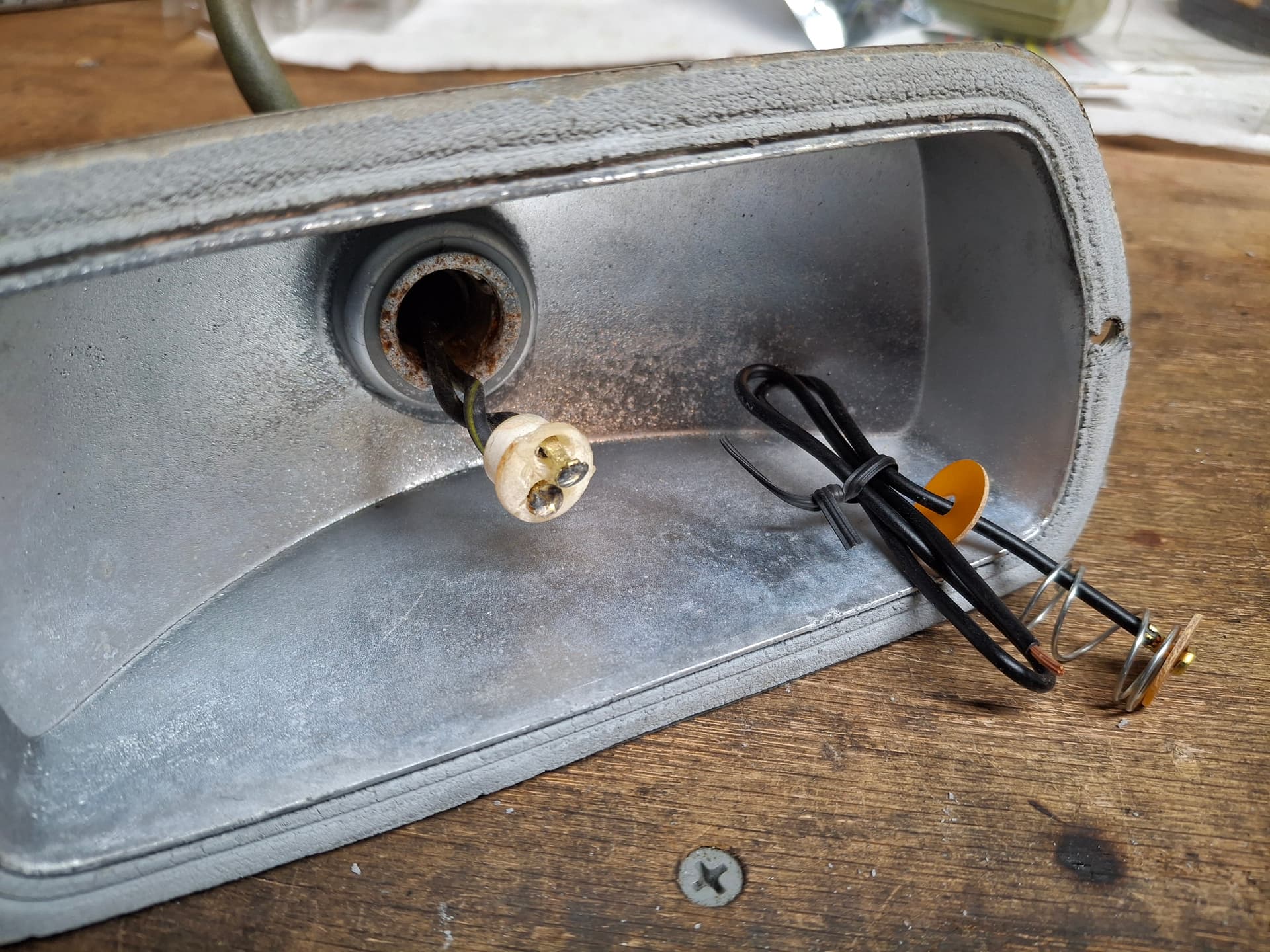
The tail light bulb plugs were beyond repair. On top of that issue, my electrical system doesn’t have a turn-signal switch and uses a dedicated three-way toggle to actuate the turn signals (remember I’ll be cruising to my local Cars and Coffee in this thing to advertise for RMVR and need signals). Using the low-watt filament of the 1157 bulb wouldn’t give enough brightness to overcome the brake light, so to address both issues, I decided to experiment with adding a second bulb to where one high-watt bulb lights for the brakes and the other high-watt for the signals hoping the difference in brightness will make the turn signal apparent while the brake light is lit. After some searching, I found 1156 single-filament sockets that I could make work in the housing holes. I drilled a new hole at the bottom of each housing, installed new LED bulbs, and installed the sockets. Once I energize the electrical system, we’ll see if my scheme works.
Front Turn Signals
The front turn signal sockets were also beyond repair, and I needed a single-filament 1156 bulb anyway since I don’t have running lights and only need turn signals. I was able to locate a universal single-filament replacement kit and got it installed without too much issue. I angled the 1156 bulb to where the locking pins work with the 1157 housing, and a bench test shows good contact and brightness. The lenses are badly cracked and need replacing, but they aren’t cheap at about $200 for the pair and can wait. I might try to heat and bend some polycarbonate into shape and make my own lenses at some point. For now, I’m going to cover them in clear tape to keep them intact on track.
Post Alert:
@jonUU
@Sportsracer
@Datsun78
@Bob_Alder
@Rich
@Nick_H
@jackson_prime101
Fire Suppression System
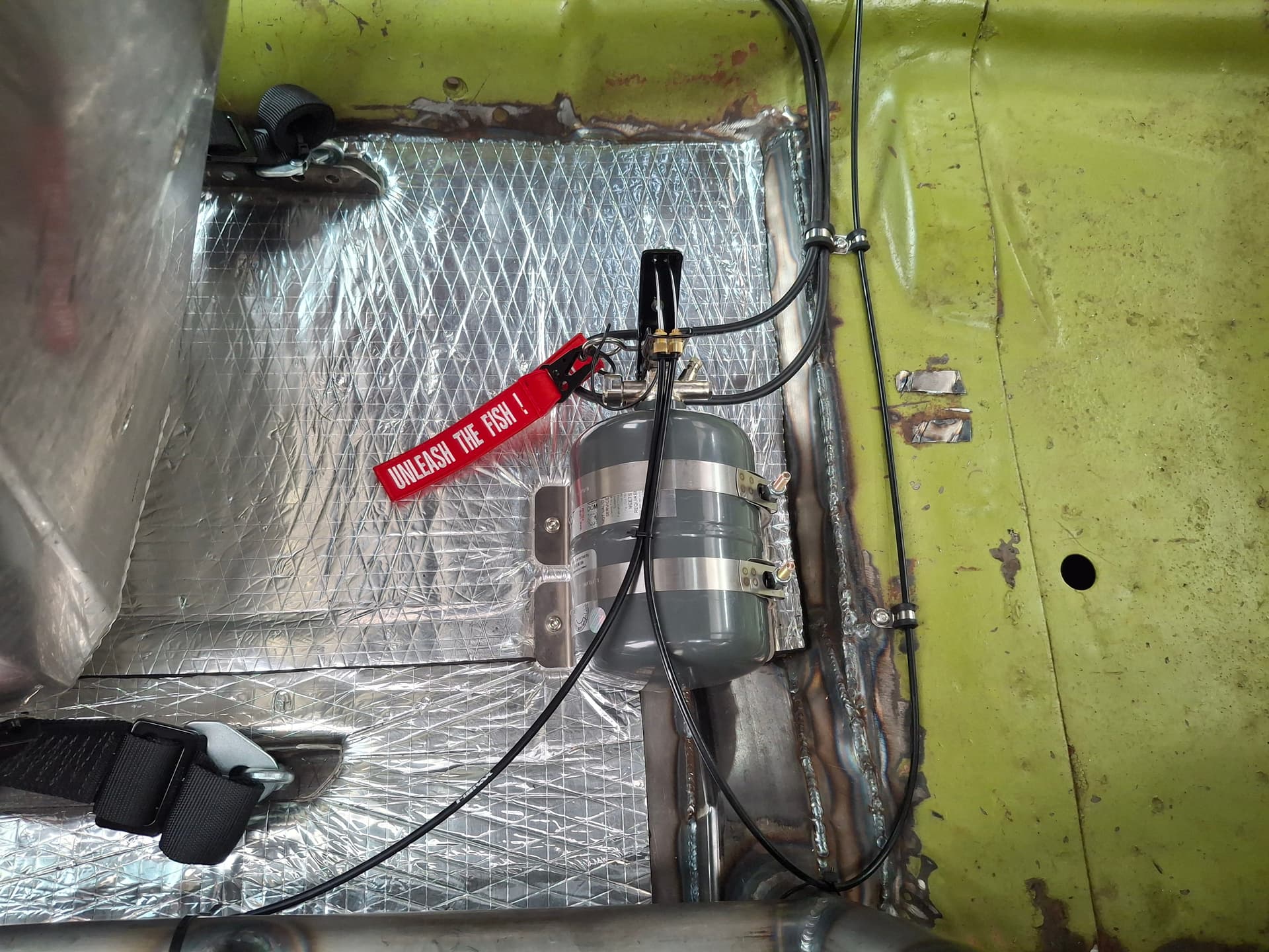
The Lifeline Zero 360 system came in (part 106-1-004, FIA approved, 2.25kg (5 lb. equivalent) of FK 5-1-12 liquid clean agent). For weight balance, I considered that needed additional weight mid-car on the left side. After experimenting with the bottle atop the transmission tunnel (awkward to pull the pin when seated), beside the seat on the drive-shaft tunnel (too easy to accidentally hit the bottle lever), and behind the seat, I settled on behind the driver’s seat for both ease of access to the pin before climbing in, safety from accidental discharge, and for weight placement.
The written description of the kit did not match what I actually received, and the kit came with only one tee fitting and one four-way cross fitting when it claimed to have more tees. It also came with a rather short coil of sheathed aluminum tubing for a kit advertised for production cars. At a $700 price tag, I wasn’t impressed with how they skimped on fittings and tubing. The system is well made and with a March 2026 FIA tag, so that’s good.
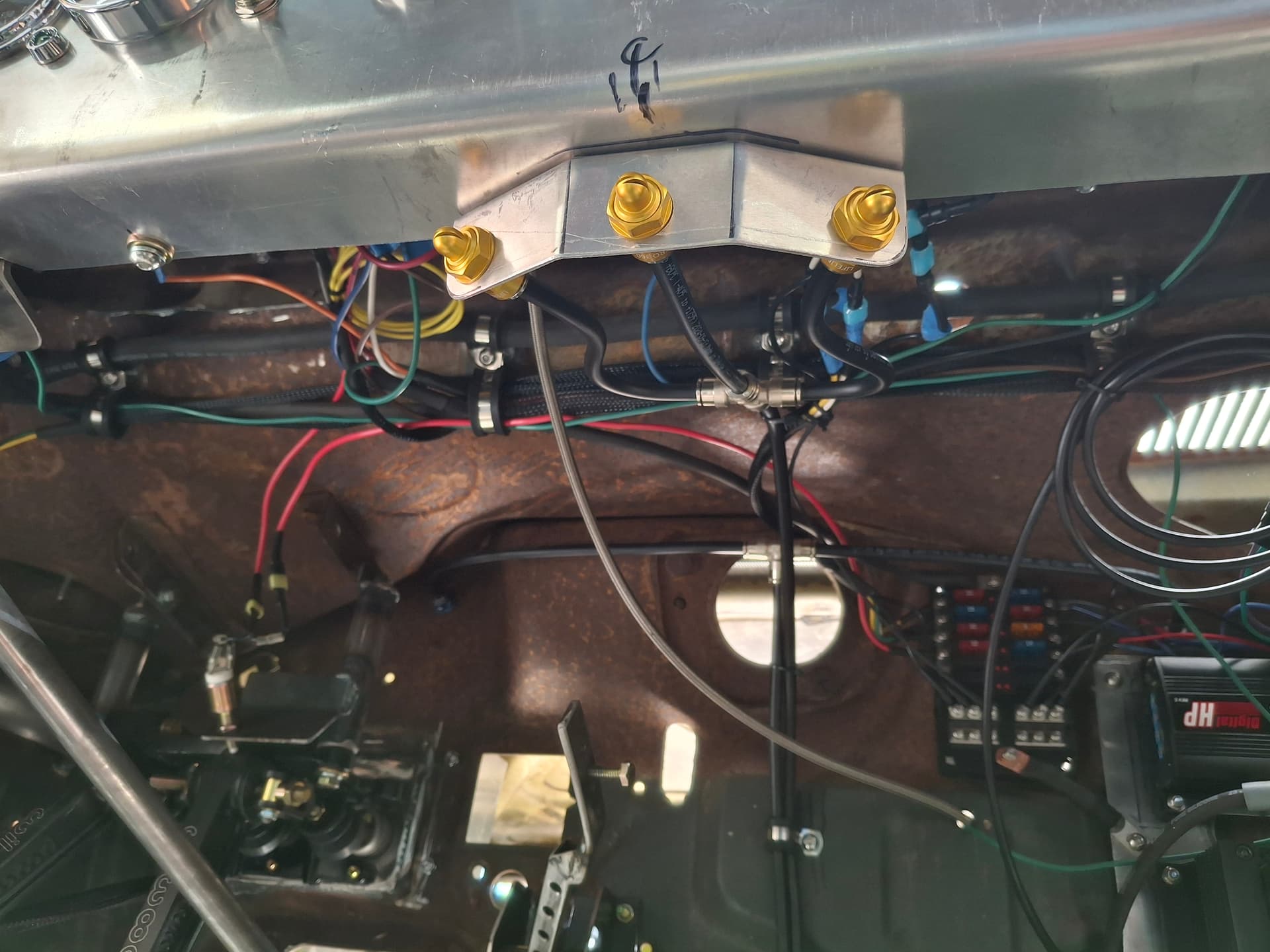
My initial design based on the website description of nozzles and fittings was to have two nozzles in the engine compartment, two in the driver’s compartment, and one in the trunk compartment. However, I had neither enough tubing nor enough fittings to make this plan work. Since the fuel cell and fuel pump/filter cluster are separated from the driver’s compartment with firewalls, I decided that three nozzles in the driver’s compartment with the volume of agent compared to the compartment volume will fill back into the trunk at least twice the volume of the compartment to put out any fire back there. I laid out the system where one branch off of the bottle’s tee feeds the two engine compartment nozzles and the second branch feeds the three driver’s compartment nozzles.
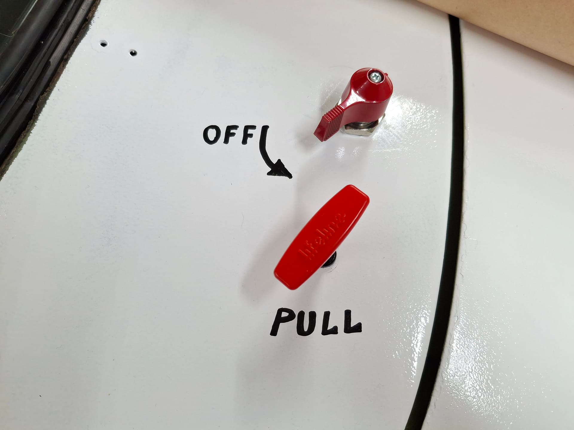
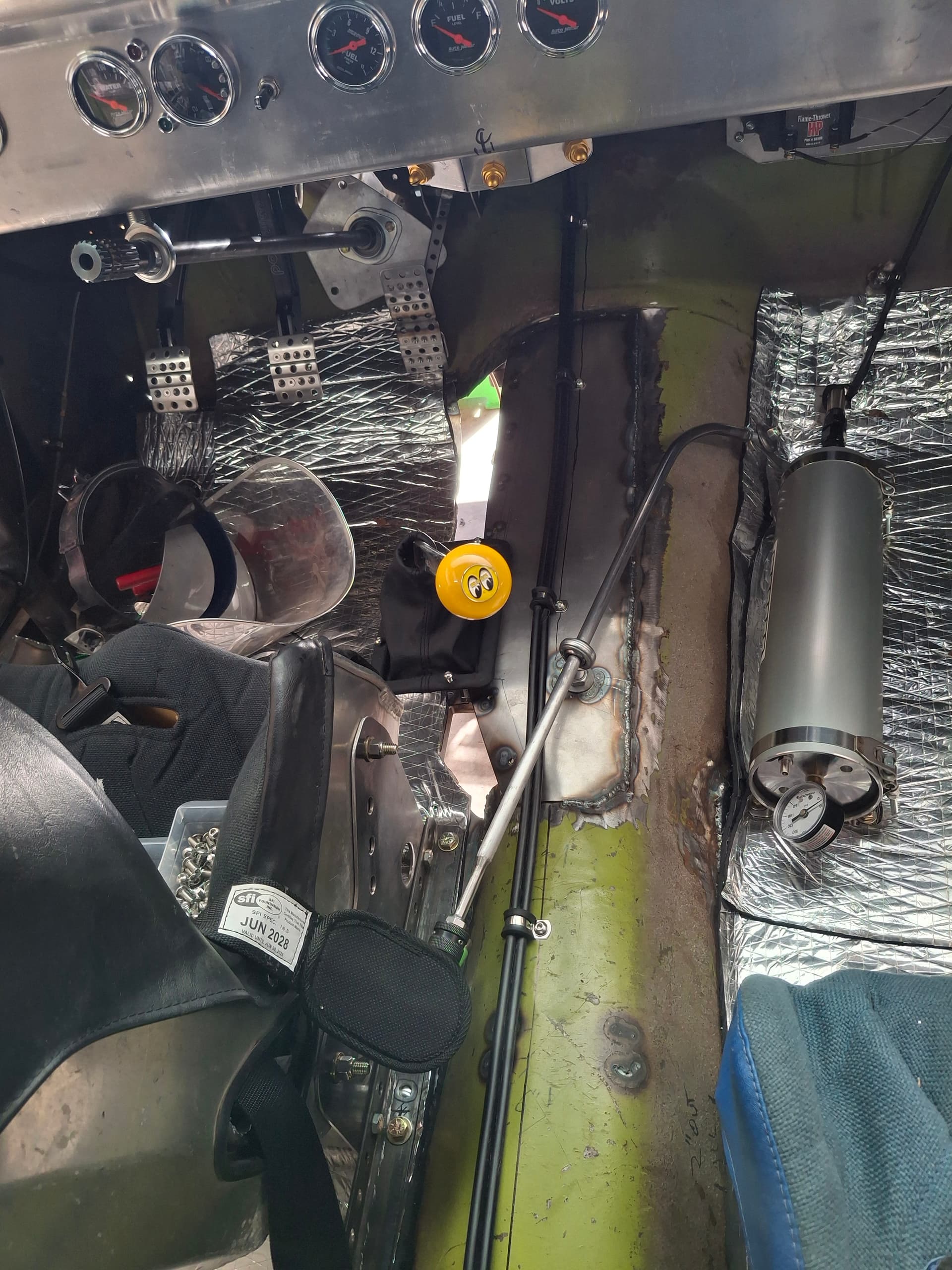
I located the 6’ pull cable on the far left of the dash easily within reach of the driver belted in and also by track workers. The cable was about 1" too short of the bottle, so I had to keep the bottle forward and outboard a bit more than I wanted. I located the 12’ pull cable on the exterior right cowl adjacent to the exterior electrical master disconnect switch. With this redundant configuration, the driver has easy access to the fire/electrical controls, track workers have access from the left side if they are willing to reach a hand just inside the car, and track workers have access from the right exterior. I need to get some electrical and fire stickers for all these locations.
The way they designed the bottle outlet is quite stupid, using a swivel tee fitting positioned in an awkward spot that is too short to allow the bottle to be positioned with the gauge facing up with the bottle’s craddle brackets bolted directly to the floor per one of the instruction options. With the bottle in this position, the 90° bend in the lower tubing would be a far tighter radius than the minimum radius specified in the instructions and would kink the thin-wall tubing. I suppose it would work if one shimmed the brackets off the floor another 2" inches, but it’s silly they simply didn’t design the brackets taller or located the outlet in a different spot. The only way I can see the bottle positioned where you can still read the gauge and get large enough bends is with the lever facing up, the gauge on the side, and the outlets pointed out the sides, which is how I installed it. Maybe I’m just not smart enough?
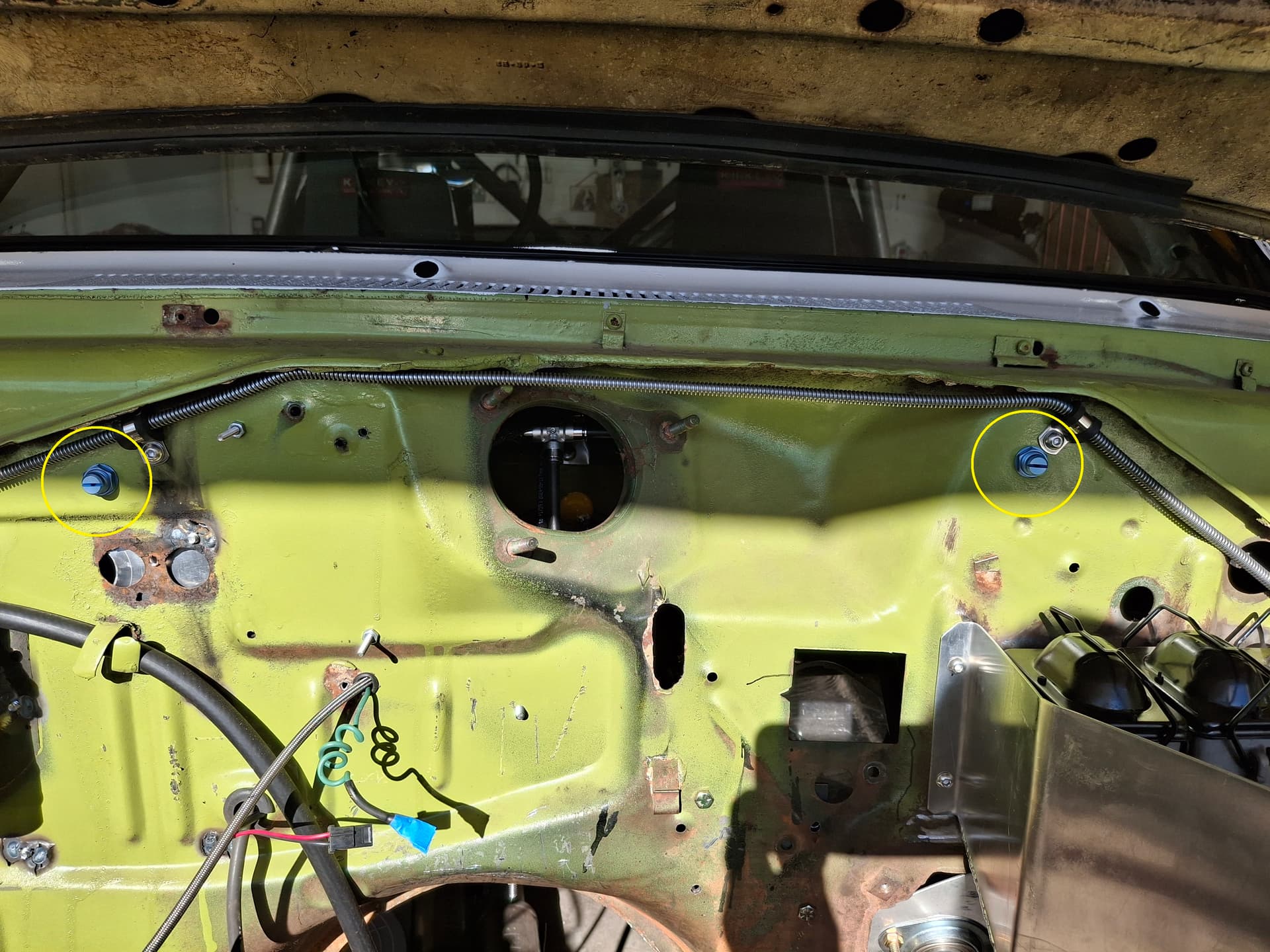
I bent up and secured the tubing running up the drive-shaft and transmission tunnel to protect it from side impact in the event of a very bad wreck that caves the rockers and cage door bars. Considering the installation instructions to point the nozzles downward away from driver’s/passenger’s faces, I bent up a three-angled aluminum bracket mounted at a downward angle under the dashboard with one nozzle pointed at the driver’s waist, one nozzle pointed straight back toward the battery and trunk, and one nozzle pointed at the passenger’s waist. With each nozzle’s 160° spread, the entire compartment gets a solid fan of agent. I placed the engine compartment nozzles on either side of the engine (circled in the photo) where the fan of agent will overlap across the entire compartment.
For the bottle lockout pin, I drilled a hole in the floor adjacent to the lever where I will drop in the pin to keep it from bouncing around. Now for another stupid design flaw. With the bottle positioned with the handle up as is must for the tubing, there is nothing stopping the lockout pin from easily vibrating out of the lever. If the bottle were facing with the gauge up, the pin would be held in by gravity, but, as I pointed out, the tubing bends won’t allow that position. The lockout pin has a cotter-pin hole drilled through the straight end, but no cotter pin was included to keep the pin from easily falling out of the lever. I installed a removable hitch-pin through the hole to hold the lockout pin in place.
To finish off the system, I installed a custom fabric clip-on tag I had made–“Unleash the Fish!” My intent is to hang this tag from the roll cage in the door window opening whenever the bottle is locked out. When I prepare to grid, I unclip the tag from the door opening, clip it to the safety pin, and remove the safety pin to arm the system. When I pit, I install the lockout pin and move the tag to the door opening. This way, if I see the tag in the door opening, I know the system isn’t armed and vice versa. Here’s hoping I’ll never have to use the system, but it’s nice knowing it’s there.

Post Alert:
@jonUU
@Sportsracer
@Datsun78
@Bob_Alder
@Rich
@Nick_H
@jackson_prime101
I worry 'bout you, Justin. You’ll recall the guy who built a yacht in his basement and then realzied couldn’t get it out. Well, about paint. Your car is going to be pretty much fully fabricated and assembled here pretty soon. Are you going to disassemble it entirelty for paint? Just something that keep me up at night worrrng about you.
Justin, it looks like the build is progressing along nicely. Are you still hoping/ planning on the maiden race being RAKC? I’m really looking forward to seeing the Cuda on track.
I’ve been building a new exhaust header for the Bobsy. This time a system with tapered primaries, a new 15 degree collector and a reverse cone megaphone secondary set up. The tapered primary set up has been especially challenging as the specified tube length is quite short, 12” for each diameter. (1 3/4 & 1 7/8). Cylinders 1&2 weren’t too difficult but keeping them short enough and still leaving enough room for cylinders 3&4 was the object of that part of the exercise. “Folding” the primaries for 3&4 in the remaining space and getting the specified length has been challenging. Finally got #3 fabbed up and tacked the tubes together. Now to start on #4. Sorry no pics just yet, maybe I’ll shoot some today and post them.
The race with SWMS last weekend was fun and the drive to the track wasn’t too bad. The track was a real arm workout. 12 turns in 1.7 miles, with 2 of the corners being very slow, 28 and 32 mph. Met some very nice racers and they all were very courteous on track. About ten cars in my run group with about 50 cars total for the event.
Best
Tom
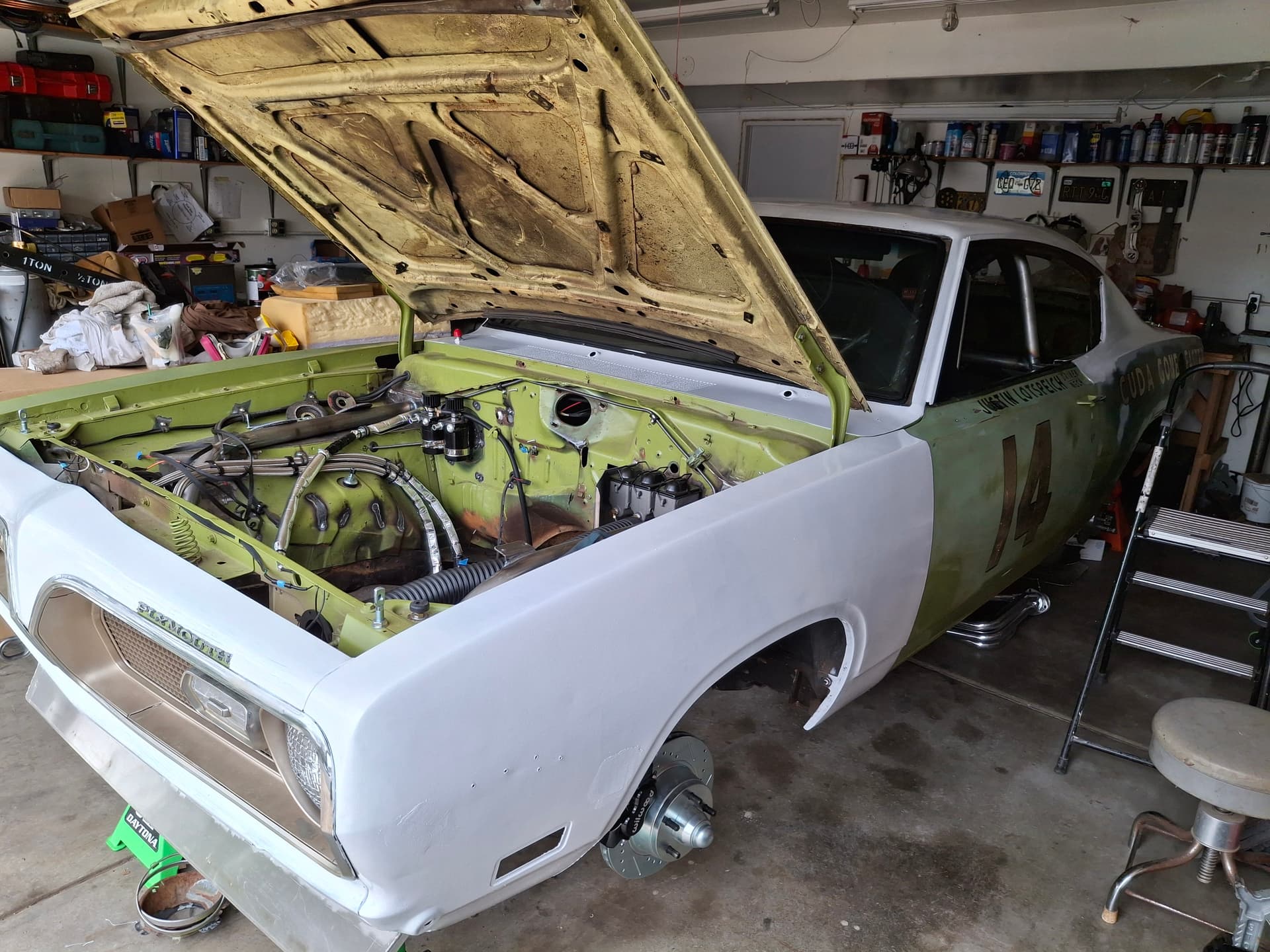
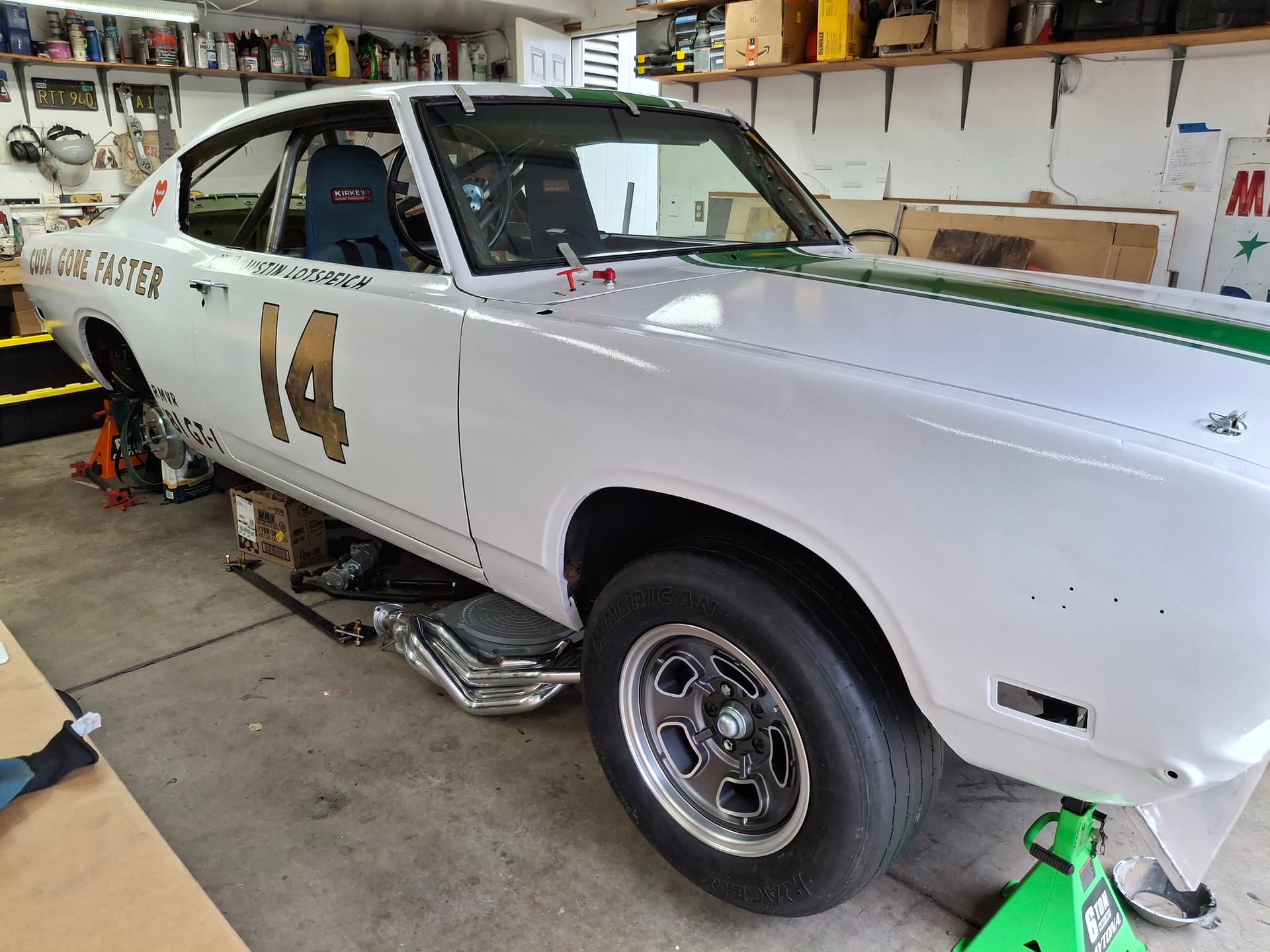
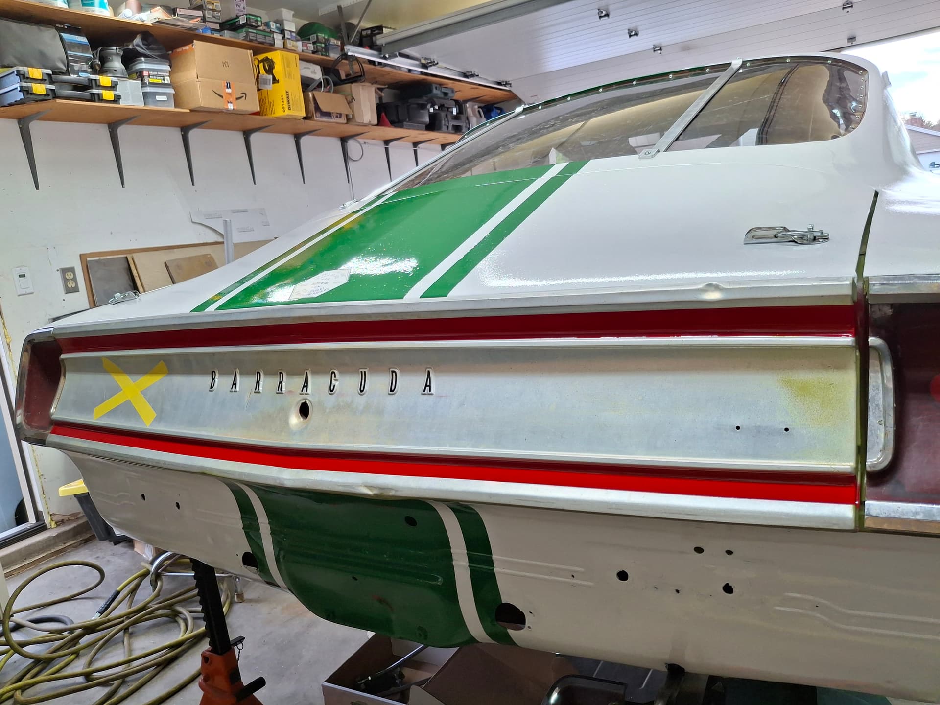
You know what, @Bob_Alder, I knew I forgot something! Lol. My initial intent was to build the car and get it on track this season with a provisional logbook where I could test and modify as necessary before doing the final bodywork and paint in case I need to widen the quarters or anything. This coming winter, I was going to tear the car down to sheet metal only, have it media blasted, and then do the final bodywork and paint. However, after the Eligibility team nixed my request for a provisional logbook on the grounds that they didn’t like the paint ![]() , I changed direction and am now ready for the reveal:
, I changed direction and am now ready for the reveal:
I got a gallon of Rustoleum white and Tractor Supply Oliver green enamel. The Oliver green was too yellow for my taste, so I mixed a quart of blue into it for a darker green. The white to too white, so I cut it with a bit of blue and black. Masking the car and tarping my garage to spray it was way too much hassle for my intent of a “temporary” fix, so I did something crazy; there’s a first time for everything, though. I wiped down the car with acetone, masked the necessary bits, and used a 6" foam roller–yes, a bloody roller cartridge and paint tray–and 1" brush to paint one coat of my custom “Cuda White,” let it cure 24 hours, and rolled on the second and final coat. I did this with garage door open on those couple 35 degree days to get the best flow out of the paint and to freeze my butt off.
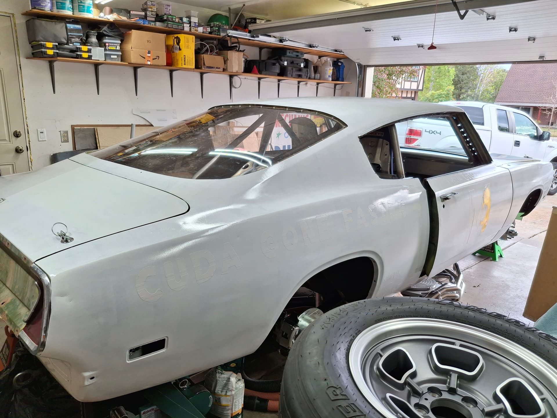
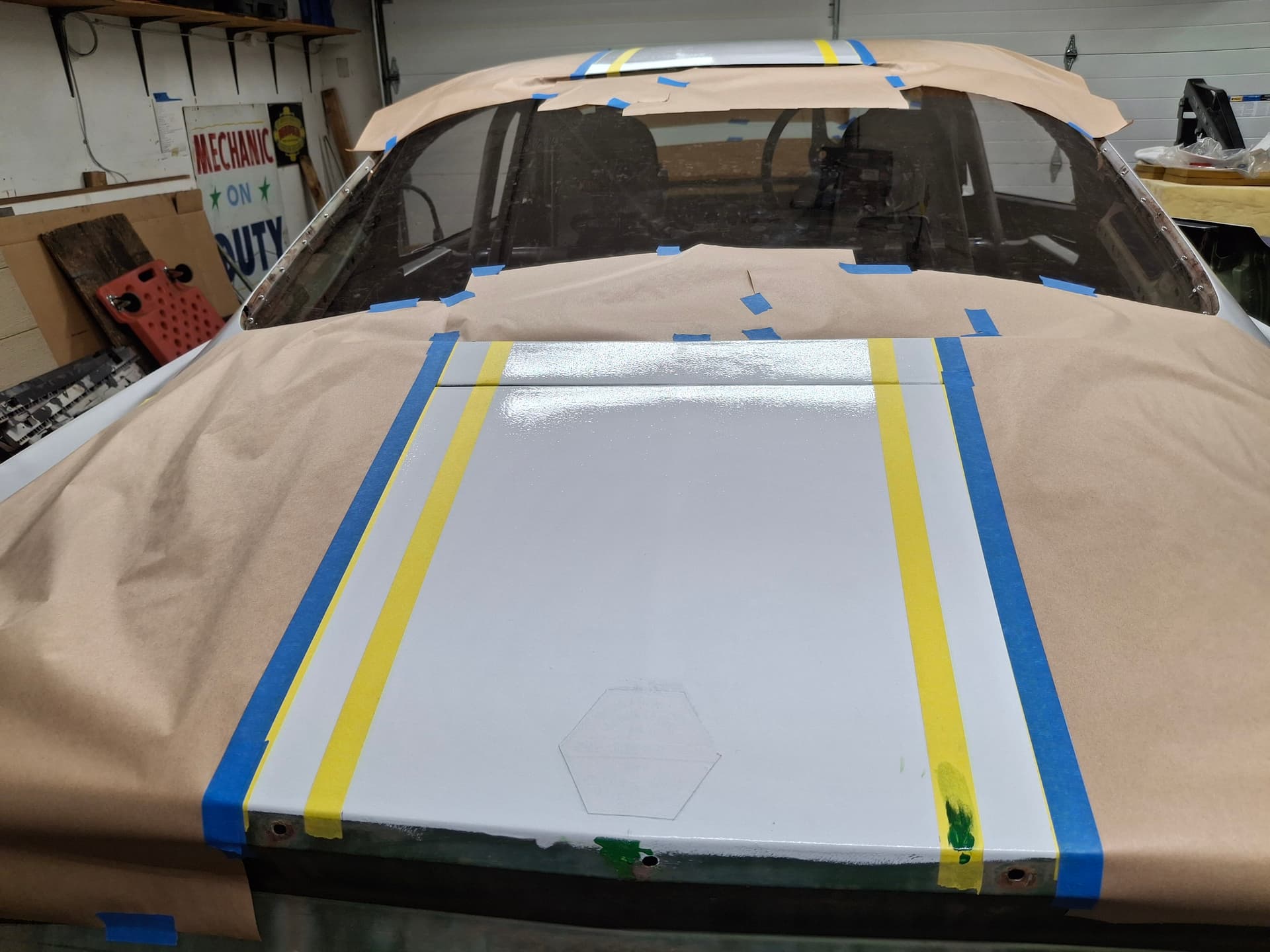
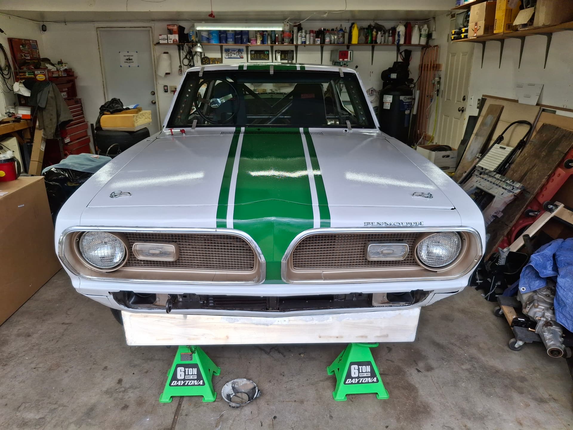
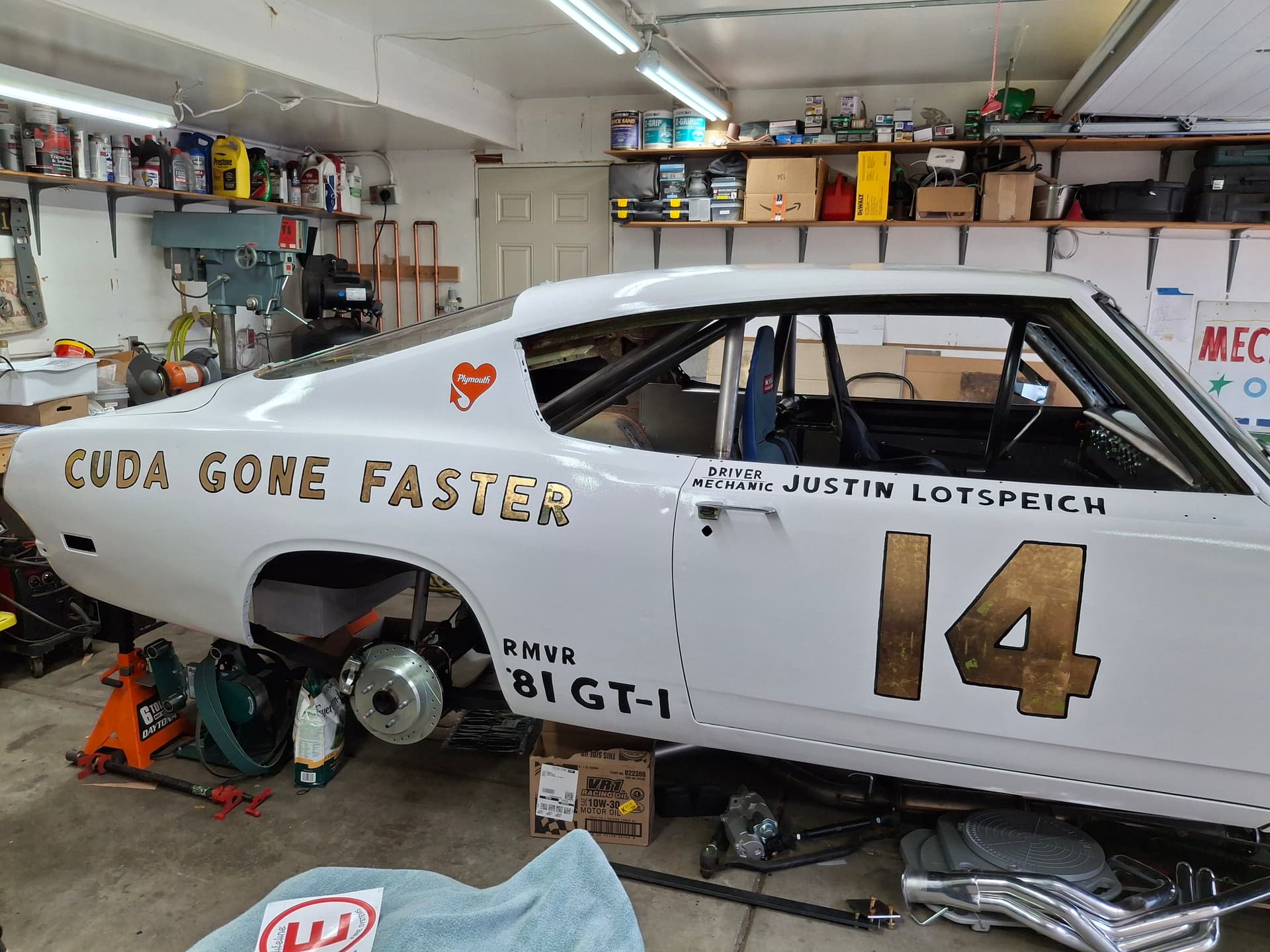
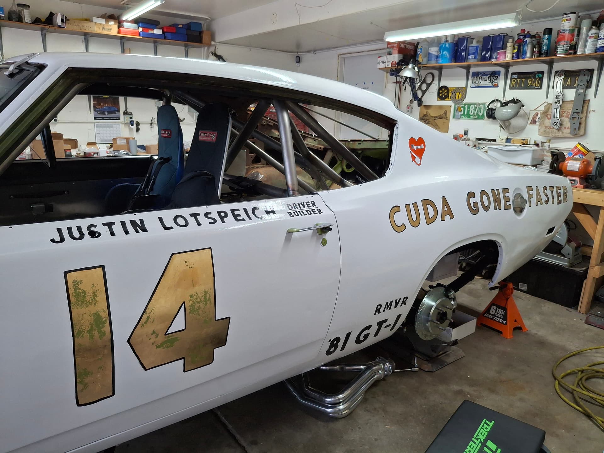
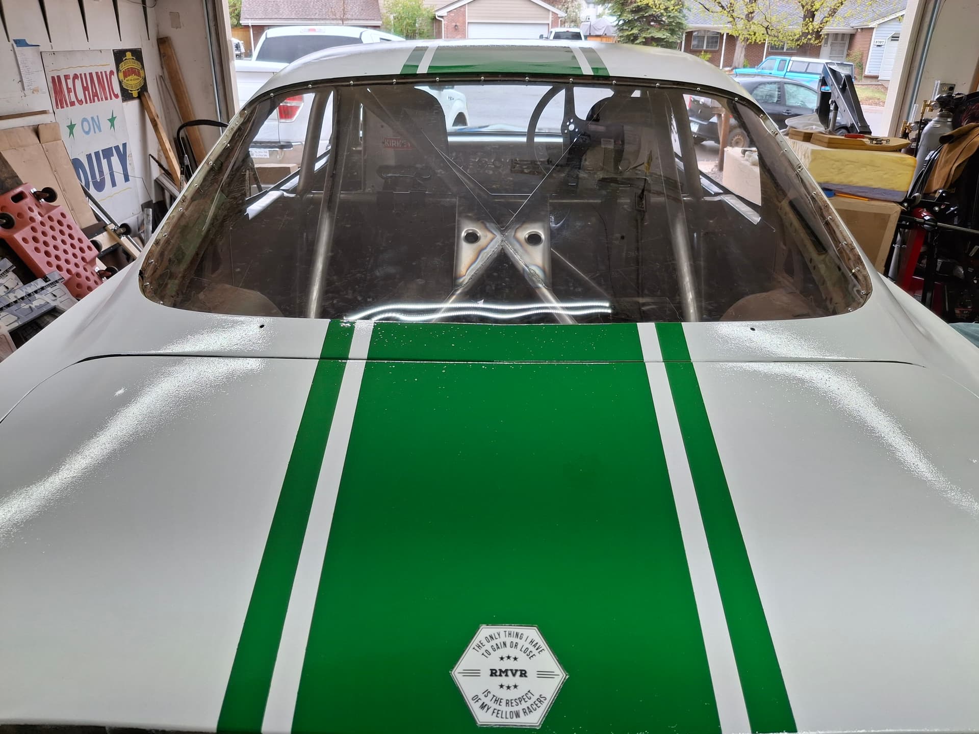
After giving the white a few days cure, I experimented with a grease pen and masking tape on a Le Mans stripe scheme until I found the balance I liked. My inspiration was from Jack Werst’s 1968 Barracuda drag car “Mr. 5 & 50,” but I think the main stripe is too wide for the grille and the outside stripes too narrow for the car. I narrowed the center stripe to 12" in the front with a 1" white space and then 1-1/2" outside stripes. Ages ago (2005 or so), I sprayed a 1966 Mustang coupe with traditional Shelby GT350 stripes and remembered how the stripes were narrow in the front, widened a lot at the windshield, narrowed from the front roof to the back, and narrowed further at the deck lid all to trick the eye into thinking the stripes looked straight. For the Barracuda, I found the centerline of the car and mapped out the outside fender/door/quarter panel contours. I copied those general changes in contour for the center stripe with the other stripes even but following the center stripe. It ended up meaning the front of the hood was 1-1/2" narrower than at the windshield, the front roof was the same as the lower windshield and tapered back 3/8", and the deck lid tapered an additional 1/4" to the back. After I masked the stripes, I rolled on one coat of my custom “Cuda Green,” let it cure 24 hours, and applied the second and final coat. I also repainted the red outline and the black lettering on the deck lid aluminum trim panel. Eventually, I’ll strip it and scrub it to clean off the green overspray and restore the aluminum.
I worried that masking the lettering and numbering I already did in gold leaf would harm that work, and it did. Even using low-adhesive tape and doing the old trick of sticking the tape onto my pants/shirt before applying it to the car to dull the adhesive, the tape pulled of some of the gold leaf and most of my black pinstriping and lettering, but the result was an interesting patina as if someone took an old car, masked the lettering/numbering, and painted it. I redid the black pinstriping and lettering and called it good.
All in all, I am surprised by what I could do with a roller. It has heavy orange peel, but I’ve seen far worse from many spray jobs. I didn’t have any runs, although I painted over some already there ![]() Despite my best efforts, the enamel went off very quickly even though I painted it back during those two 35 degree days to where I could only slap down the loaded roller, roll out about 8" wide of paint to the centerline of the car, and back-roll with one pass to even out the paint thickness and surface texture before the paint started going off. If I touched it after that, it would get fuzzy/dull and leave nasty lines. Due to this struggle, there are a few rolling lines I couldn’t smooth out for the life of me, but I’ve come to terms with them. The car isn’t jammed, so the green remains on the jams, engine compartment, and interior, but the exterior is more than “presentable” for a race car. Provisional logbook be damned, I’m shooting for a regular logbook now so I can get on track with all you fine people this season and beyond. When the time comes somewhere in the future when I feel like it, I’ll tear down the car, have it blasted, and do the final bodywork and paint.
Despite my best efforts, the enamel went off very quickly even though I painted it back during those two 35 degree days to where I could only slap down the loaded roller, roll out about 8" wide of paint to the centerline of the car, and back-roll with one pass to even out the paint thickness and surface texture before the paint started going off. If I touched it after that, it would get fuzzy/dull and leave nasty lines. Due to this struggle, there are a few rolling lines I couldn’t smooth out for the life of me, but I’ve come to terms with them. The car isn’t jammed, so the green remains on the jams, engine compartment, and interior, but the exterior is more than “presentable” for a race car. Provisional logbook be damned, I’m shooting for a regular logbook now so I can get on track with all you fine people this season and beyond. When the time comes somewhere in the future when I feel like it, I’ll tear down the car, have it blasted, and do the final bodywork and paint.
To @Sportsracer Tom’s question, I just spoke with Pete today, and our goal is to dyno the engine by June. If everything goes well on the dyno, my goal is to do a preliminary shakedown at the IMI Motorsports drifting/kart track in mid-June to test the clutch, brakes, systems for leaks, etc. If I don’t have major issues there or if I can repair any in time, the formal track shakedown will be at the June PMP Friday test and tune. I have a number of people strongly pushing me to actually enter the June race, but I’m on the fence about putting that pressure on me to shake down a new build and race it on the same weekend. I’m more inclined to shake down at June’s PMP test and tune (volunteer Sat/Sun) and register to race at August HPR followed by RAKC. I am very disappointed we aren’t racing at La Junta since I’d do that too, but a rumor is in the wind that a group of RMVR members may be interested in pooling money to rent La Junta for a weekend possibly in October since there is concern the lack of RMVR financial support may lead to the demise of the track.
I give you all my almost-finished product:
Post Alert:
@jonUU
@Sportsracer
@Datsun78
@Bob_Alder
@Rich
@Nick_H
@jackson_prime101
1 Like
You are amazing. A paint roller??? That’s thinking out of the box. But…it looks good. I’m imprsssed with your injunuity. You are amazing!
Justin
I think the car looks great! The lettering and stripes really accent the cars’ lines and give it a professional look. From the pics, I would have never known it’s a roller paint job, Amazing!
My exhaust header project is moving along slowly. For some reason the pipes have moved quite a bit after final welding. The fit up went well with no gaps, so I was hoping for less problems. Strangely the first set had more gaps but I had virtually no movement after final weld up. The curves one encounters with race car projects!
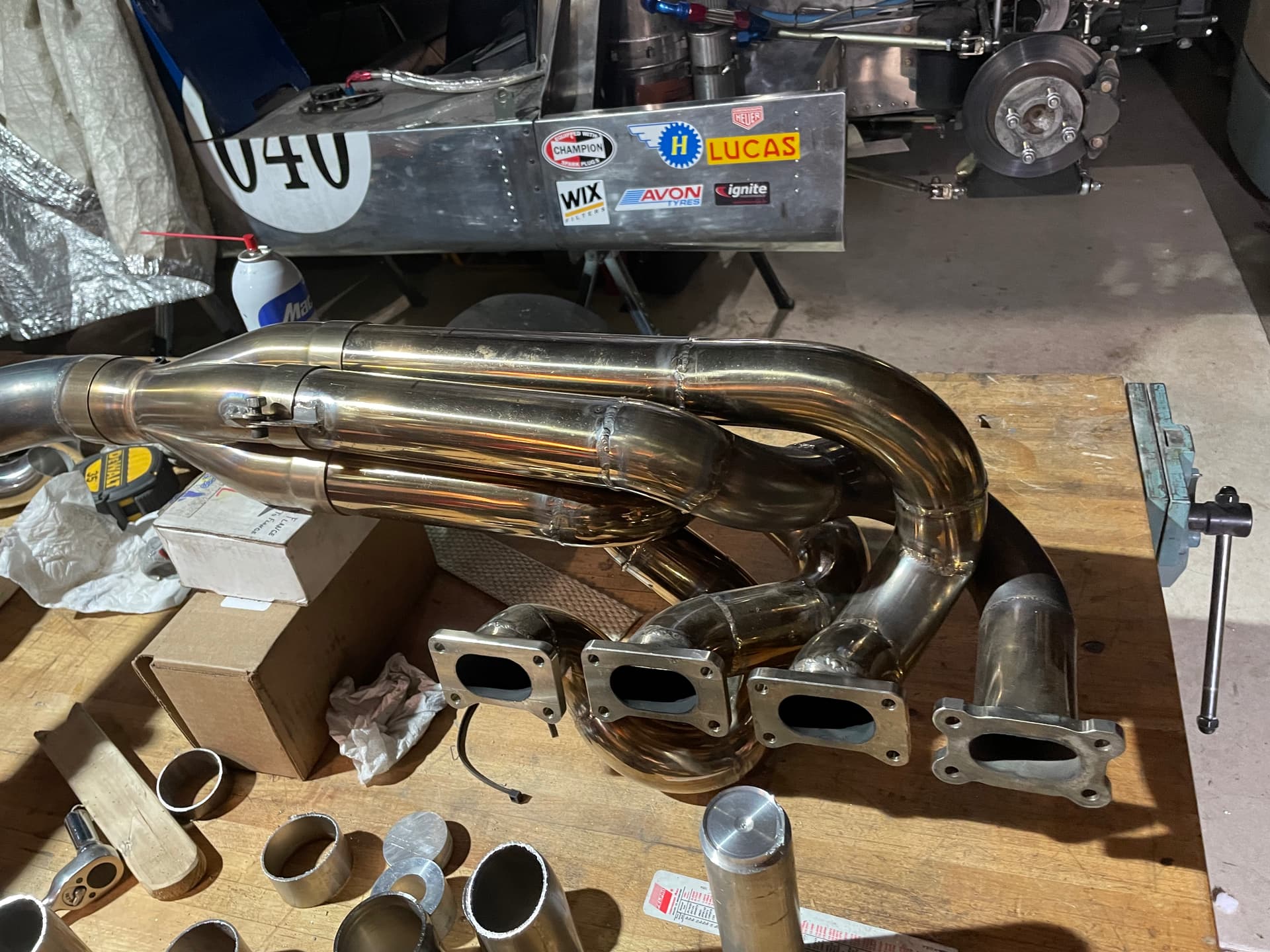
The first header, all stainless, polished. Had great top end power but nothing below 6,000 RPM
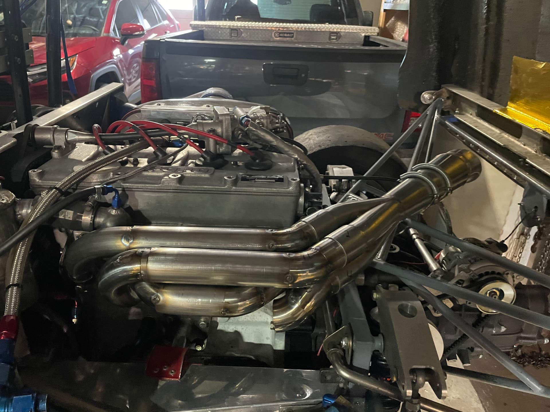
The current design, tapered primary tubes, reverse cone megaphone secondary. Mocked up and tack welded. Hoping for more midrange without much loss on top.