Thanks Bob. I appreciate all the support.
Hey Tom, thanks a lot. It’s been a fun ride so far despite all the setbacks.
Your headers are looking great, and I sympathize with the amount of attention to detail and work they take. Did they move around to the point where they won’t properly mate up? Hopefully not. Keep us updated on your progress. FYI, I’ll be at HPR Thursday night camping Thursday, Friday, and Saturday. If you end up being around in the evening, find me at my fire pit.
Dyno Day Part 1: The Pendulum of Excitement and Disappointment
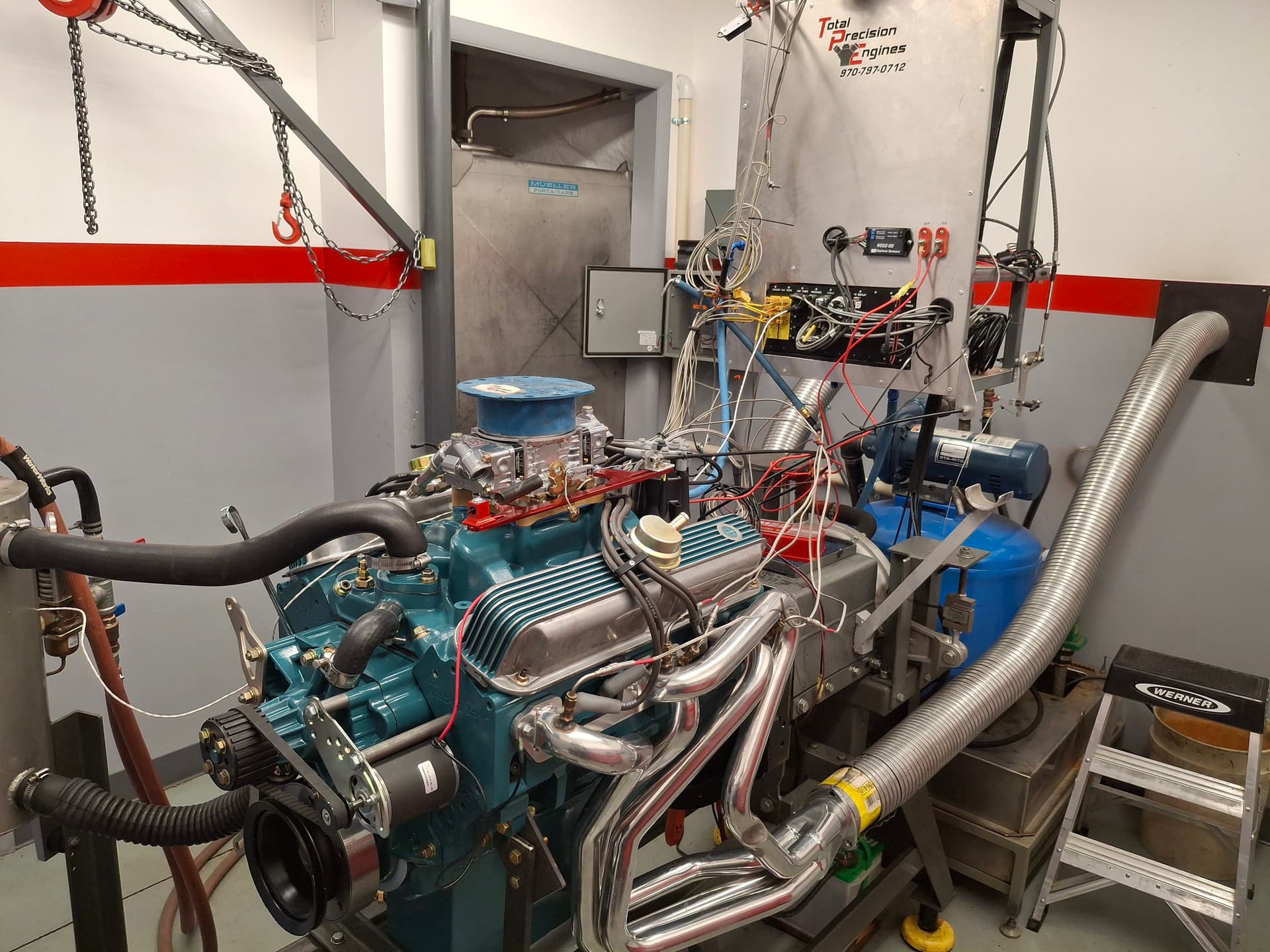
I took the engine up to Pete Christensen’s in Fort Collins Tuesday after HPR Driver’s School (I received my provisional comp license and had a blast!!!) to get it set up on the dyno and put a heat cycle into it. The plan is to go up next Tuesday the 26th for a day of dyno tuning.
Pete, Allen Letterly, and I got the engine set up with relative ease after breaking down the Formula Ford setup. We fired the engine, which took off easily enough. After adjusting timing, we put about 20 minutes of low-rpm on it without issue. Vitals all looked good, and it sounded sweet.
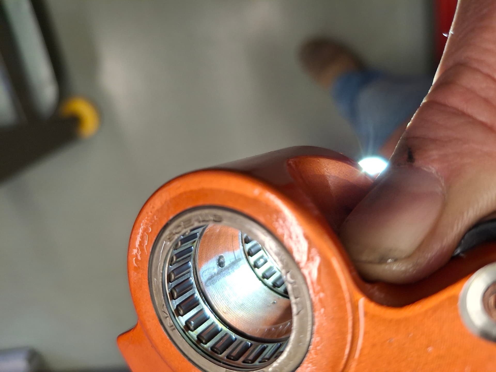
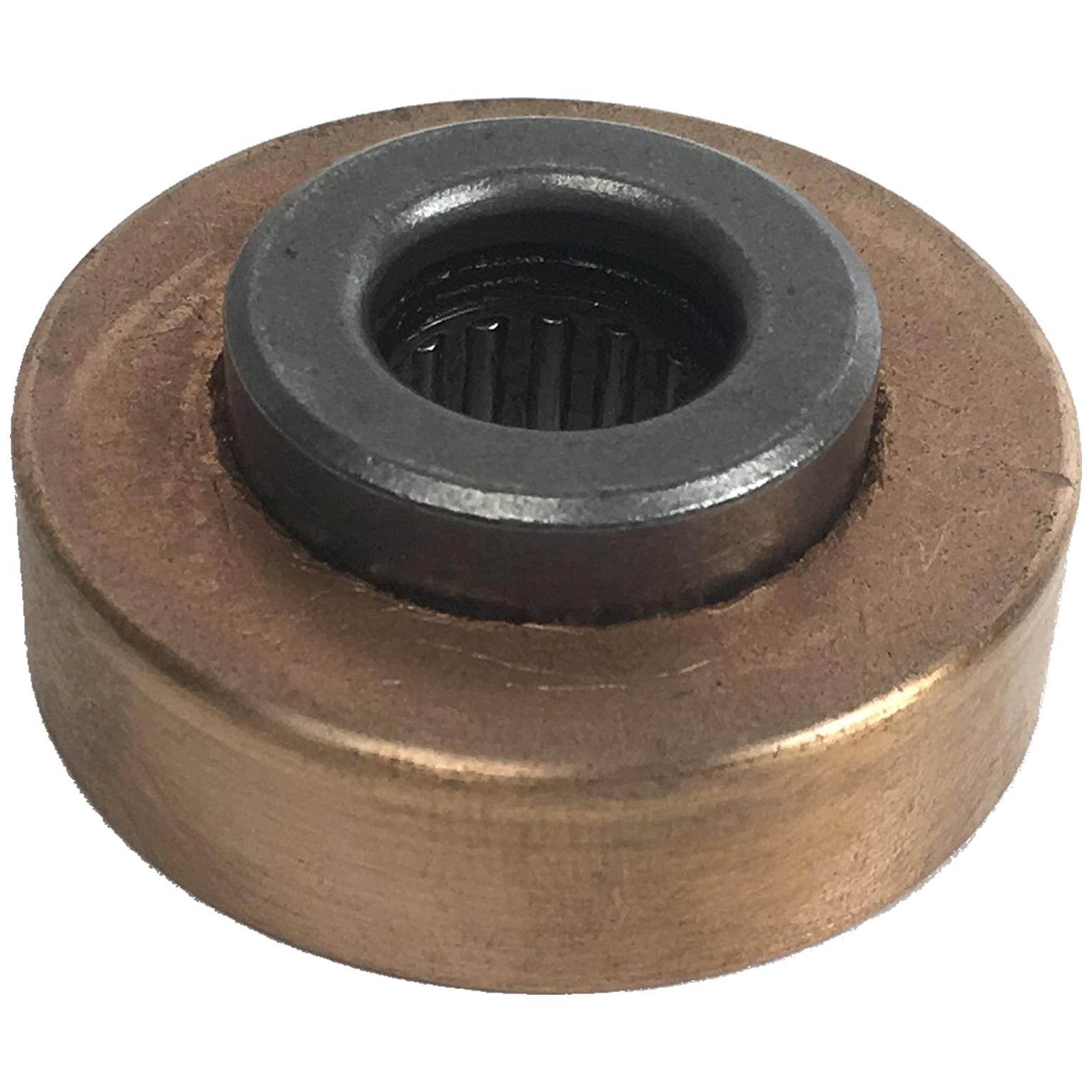
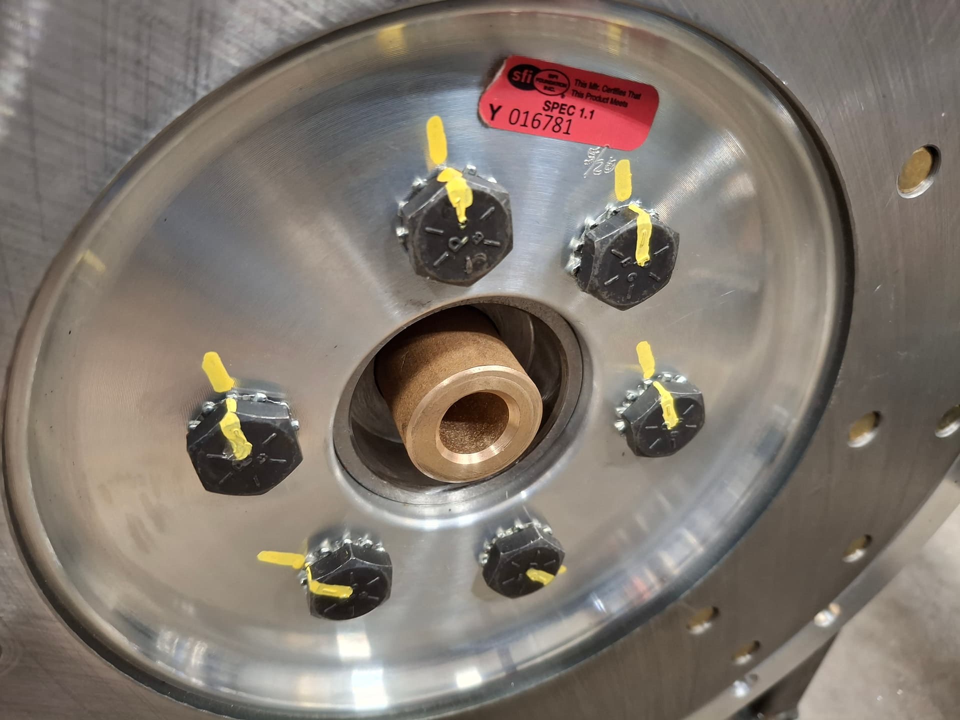
We shut it down and decided to adjust the valves for hot lash before calling it a day. That’s when the Harland Sharp rocker arm saga continued. If you recall, the first set of Harland Sharp rocker arms I received had quality issues with the anodizing and roller tip riveting , and the owner convinced me to upgrade to their premier needle-bearing full rollers. Upon removing the valve covers, we noticed about half of the push rods on both banks had varying degrees of overheating at the top—some from a light gold and others badly blued. Closer inspection revealed that many of the overheated push rods showed bone dry push-rod cups and adjuster balls.
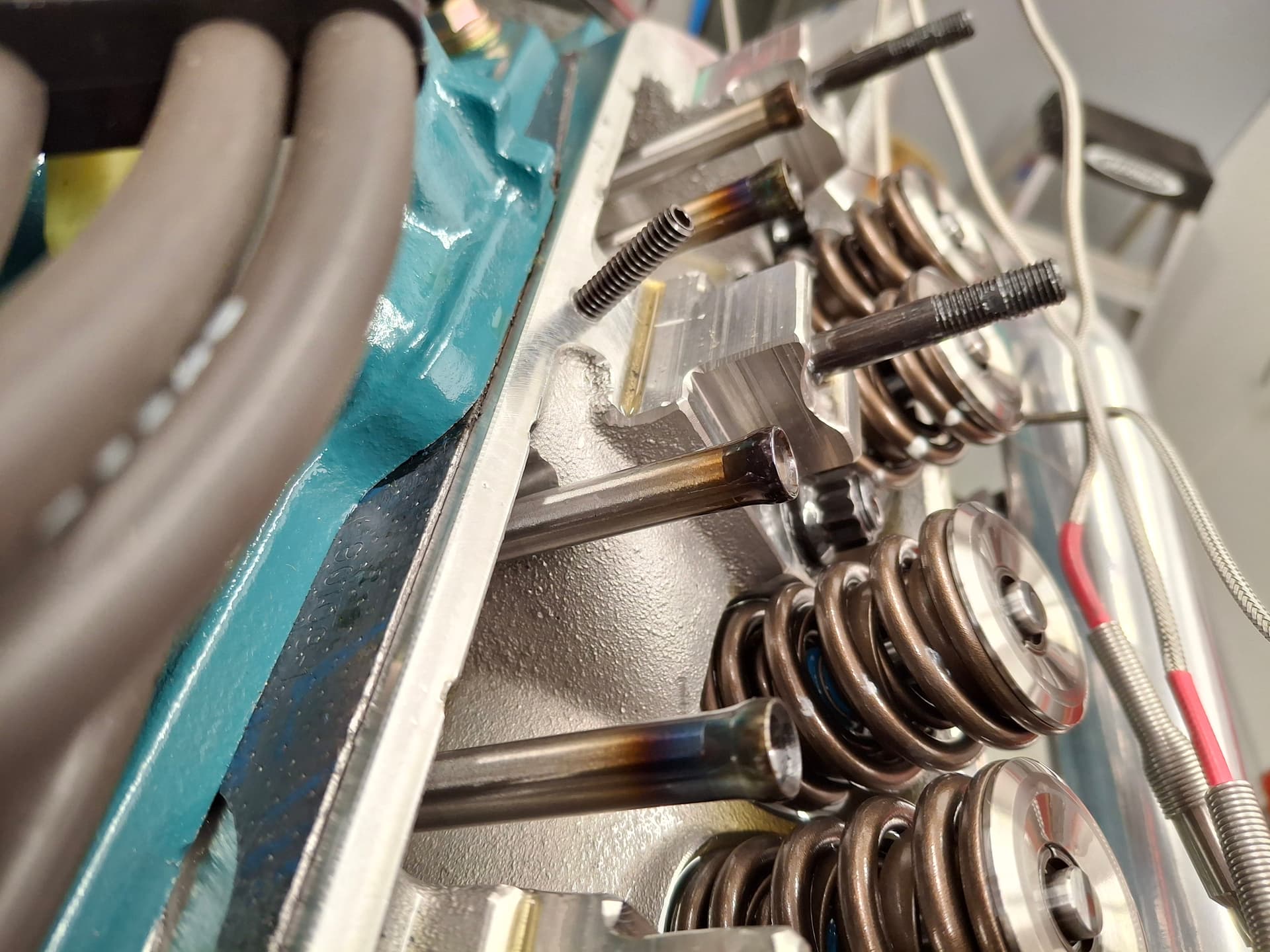
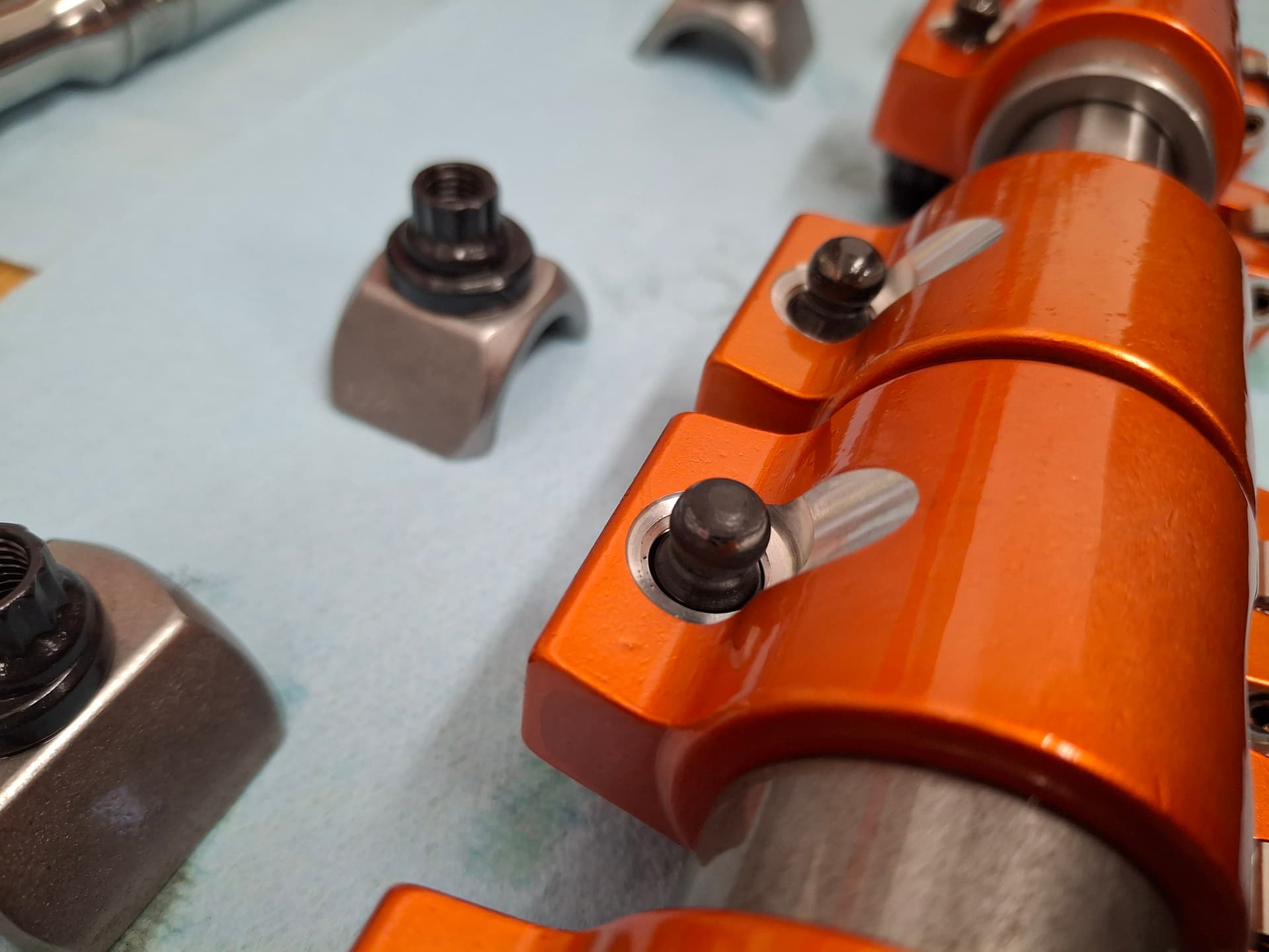
Being a shaft-mounted LA Mopar engine, the ball/cup do not receive oil through the lifters and push rods but through the rocker arm via the rocker shaft. The way things are supposed to work is that the shaft is pressurized through a camshaft, the oil exits the rocker shaft through two holes per rocker arm, the oil squeezes out to oil the rocker arm needle bearings, and the oil squeezes out through a hole drilled in the center of the rocker arm to squirt onto the ball/cup.
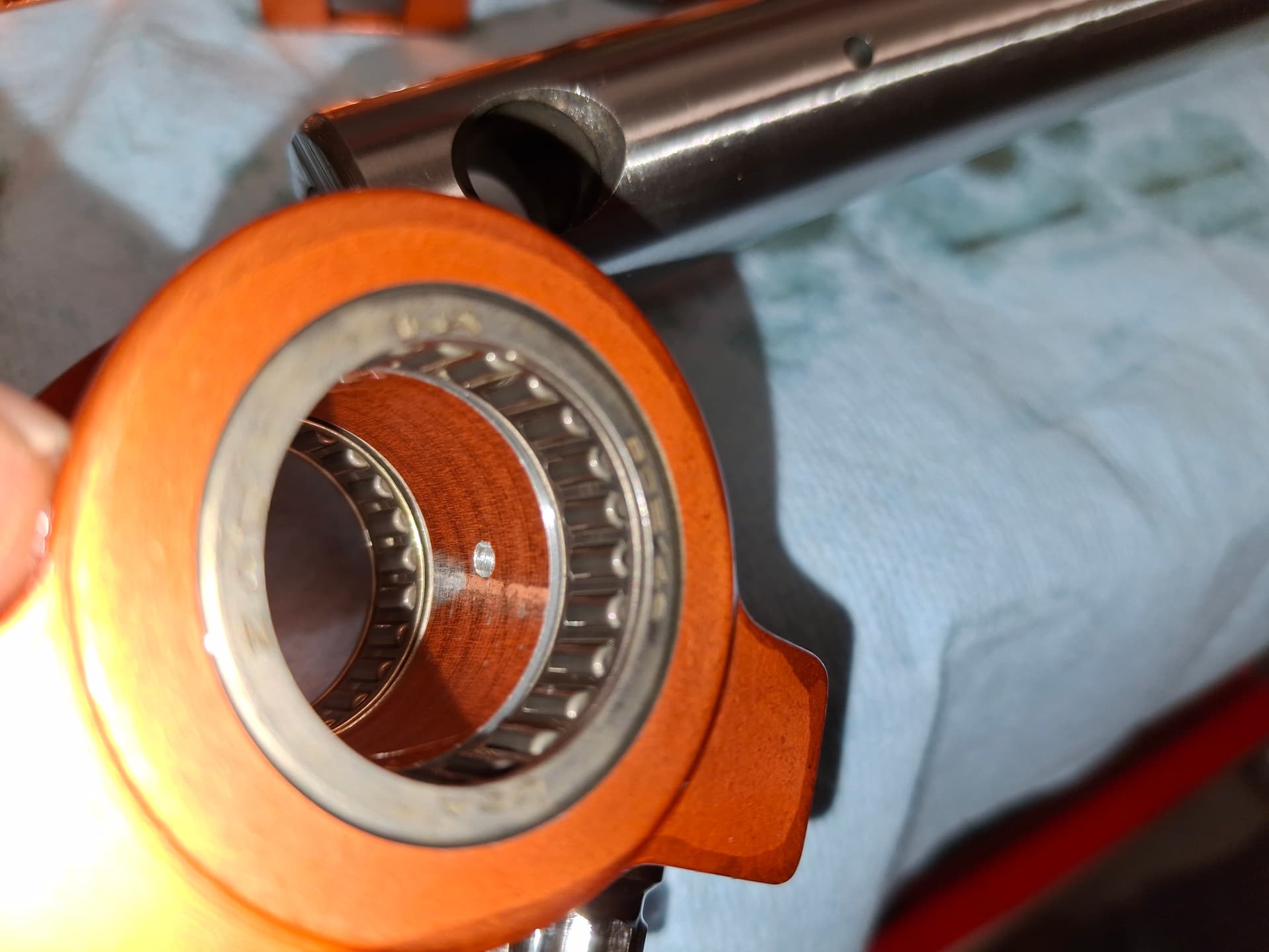
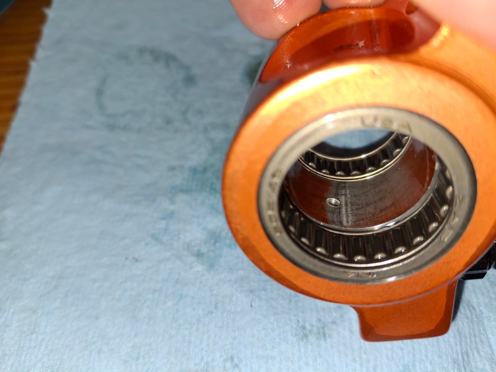
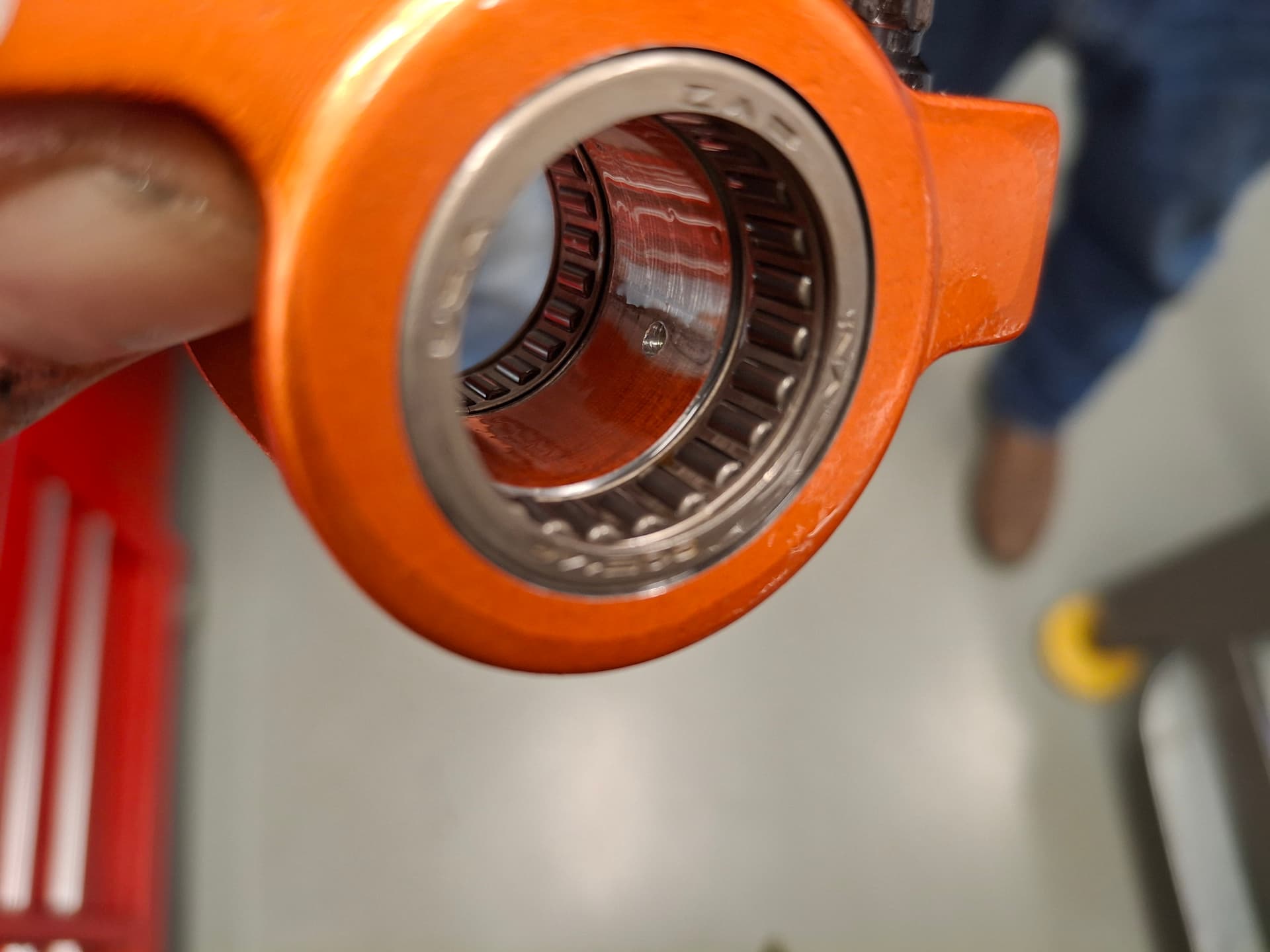
The rocker arms are built from billet aluminum and have a hole bored in the middle for the shaft with two larger bores on the ends where the needle bearings press in. Theoretically, the needle bearings should be centered on the shaft bore and be a smaller diameter than the bore to where the shaft rides on the needles and oil has clearance to make its way out of the two shaft holes, around the shaft, and into the ball/cup oiling passage. When I primed the engine on the stand, I saw plenty of oil oozing out of all the rocker arm sides and some oozing out of some of the ball/cup adjuster holes, at least on the rocker arms that were closed without load on them.
However, what we found after the dyno warmup was that the needle bearing bores appear to be either misaligned with the aluminum shaft bores or the aluminum shaft bores are not large enough to where the aluminum of the rocker arm is being forced tight against the shaft exactly at the ball/cup oiling passage, evident from a band of wear in the aluminum bore. We theorized that the contact between the shaft and aluminum body is blocking oil to the ball/cup passage and starving that joint of lubrication and cooling. Suffice it to say, all three of us were disappointed, surprised, and frustrated by the lack of quality design and manufacturing precision on such crucial components.
Luckily for me, (1) we didn’t beat on the engine enough to torch and break the push rods/adjusters and (2) later 1990’s small block Dodge “Magnum” 5.2L and 5.9L engines don’t use shaft-mount rockers but use stud-mount rockers that receive oil through the push rods. The solid-roller lifters I’m using are made to interchange with both the earlier LA shaft-mount system and later Magnum stud-mount system and have the oil-through provision. We don’t trust the integrity of the overheated push rods, and we decided that the best course of action for now is for me to order another set of push rods but this time with the oil-through provision. The current push rods I ordered without oil-through since shaft-mount systems shouldn’t require it, so they don’t have an oil hole in the lifter ball end and adjuster cup end. Before leaving Pete’s, I placed the order, paid the expedited manufacturing fee, and paid the 1-day shipping to ensure they get here by Saturday so we stick to our scheduled Tuesday dyno plans. The push rods should take care of the oiling issue, and they better be gold plated for the price.
For the rocker arms, I emailed the owner of Harland Sharp photos and a description of what we found and asked him to call me. They have a lifetime warranty against manufacturer defects, so I’m hoping they make this right without issue/argument since this will be the third set. Pete, Allen, and I concluded that the wear on the arms isn’t severe enough to stop us from dynoing on Tuesday, but I want them corrected before beating the engine on track. The alternative is that if Harland Sharp doesn’t come through with a solution that I eat the $1,300 I have in the rocker arms and buy a Comp Cams stainless steel bushed roller rocker assembly for $900 and hope for better results.
All in all, despite the issue with the rocker arms and push rods, I was very happy to see and hear the engine run well, see no internals exploding out of the block, and spend a fun day at the shop with Pete and Allen. I look forward to Tuesday’s tuning day.
Post Alert:
@jonUU
@Sportsracer
@Datsun78
@Bob_Alder
@Rich
@Nick_H
@jackson_prime101
1 Like
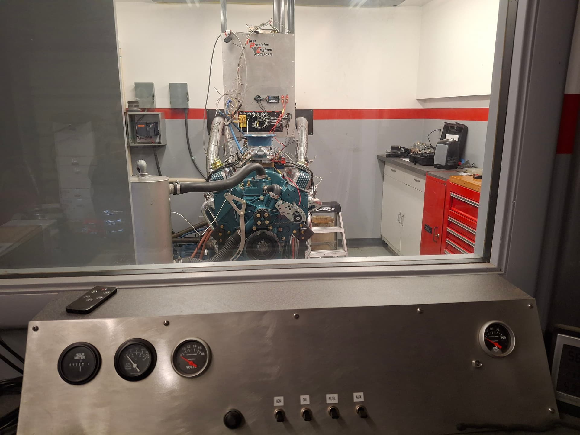
Dyno Day Part 2
I returned to Pete’s shop this past Tuesday armed with new oil-through push rods and accompanied by Nick Hill (@Nick_H) and our Chief of Tech Charlotte Roadcap who wanted to join in the fun.
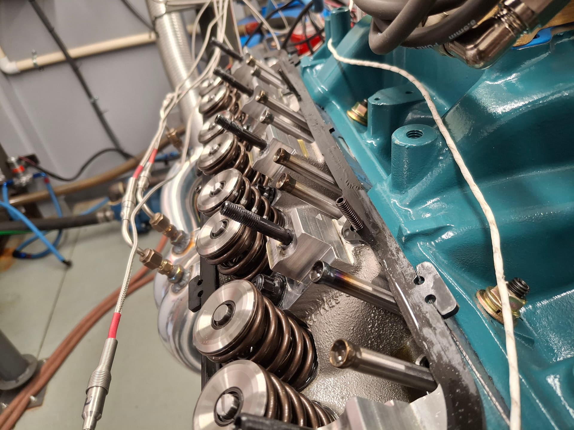
After swapping out the push rods and setting cold lash, we fired and warmed the engine, shut it down, and pulled the valve covers to check for oiling and to set hot lash. Oiling looked great with the adjuster balls/push rod cups now getting plenty.
Keep in mind that I had two goals for the engine: (1) it would not grenade and (2) it would produce 450 HP. Those might seem like pretty low bars, but I honestly went in assuming it would grenade and, if it didn’t, would be down on power. I call it realism, but I’m told I’m a pessimist ![]()
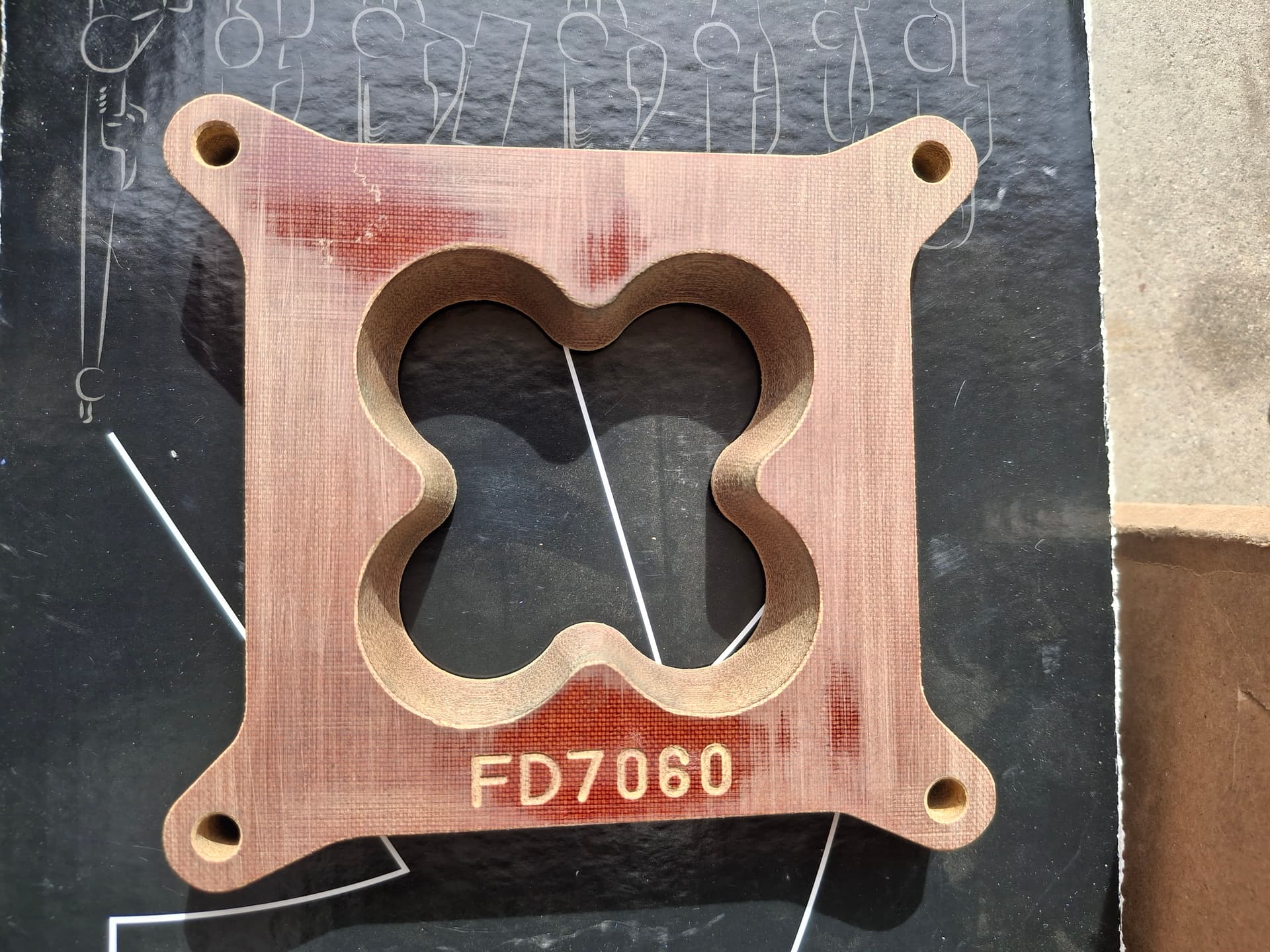
We started running the engine through its paces starting with the 1" phenolic “four-leaf clover” (as I’m calling it) spacer that Pete suspected would produce the best results. The first pull was light and lower RPM, but the numbers on the monitor had me grinning. A couple more pulls showed that exhaust temperatures looked pretty good and even, although #4 was the anomaly running very slightly leaner than the others but not dangerously.
We played with timing a bit and fattened the carburetor primary and secondary jetting by two sizes. More runs, more spark-plug inspections, and more timing adjustments told us the engine liked more timing. We adjusted the distributor advance curve as well until we found the sweet spot.
Once we had a solid baseline and were happy with the exhaust temperatures and other vitals, we swapped out carburetor spacers to try a fancy 1/2" anti-reversion spacer and a combination of a 1/2" open spacer and the anti-reversion spacer. While I’m curious to see how the anti-reversion spacer performs on the track regarding throttle response, both the combinations lost power and didn’t improve the overall powerband dynamics over the 1" “clover” spacer. The 1" spacer went back on for the final pull.
I know that some people lock their dyno results in a vault, but I’m happy to share since you’ve been on this journey with me. Both of my goals were met in that the engine ran well without mechanical issues (aside from the rocker-arm quality snafu), and thumped my 450 HP goal. Peak HP came is at 6,300 RPM at 562 and didn’t fall off significantly until 6,800. Peak torque came in at 4,600 at 528 ft.lbs. The torque curve also maintained good power across a wide spread, so we were happy to see that. Best peak numbers aside, if you average the peaks from all the 1" spacer runs, a more realistic expectation is about 555 HP and 520 torque. It looks like my intent on shifting at 6,500 aligns nicely with what the engine wants. Engine vitals looked great including good oil pressure at both idle and peak RPM and good oil temperature dynamics–and that’s without the oil cooler.
After breaking down the setup and loading everything in my truck, I drove away excited at what I built and what we all tuned. Harland Sharp is sending a new set of rocker arms, adjuster screws, and additional end-play shims to, hopefully, correct the issues. I hope to receive them next week so I can get the engine and transmission installed and the car prepped for shakedown.
A huge thanks to Pete for his use of the dyno, his knowledge and help, and his willingness to mentor, and a huge thanks to Nick and Charlotte for their encouragement and help, especially knowing it was a very long day.
Post Alert:
@jonUU
@Sportsracer
@Datsun78
@Bob_Alder
@Rich
@Nick_H
@jackson_prime101
1 Like
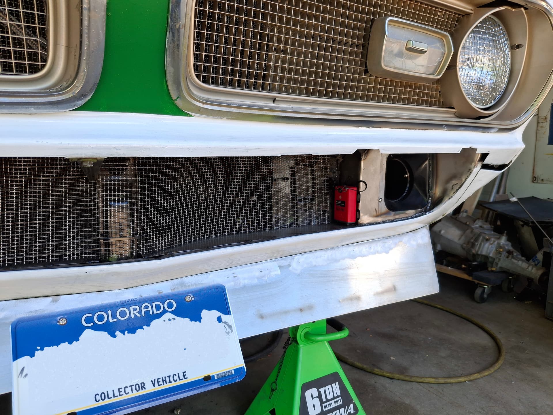
Battery
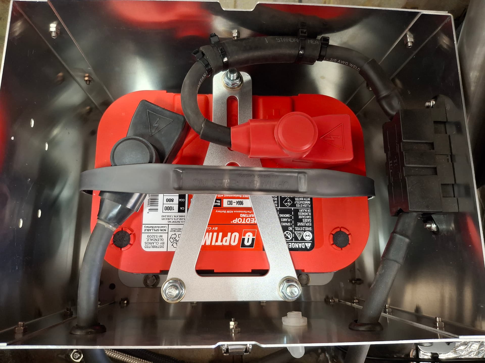
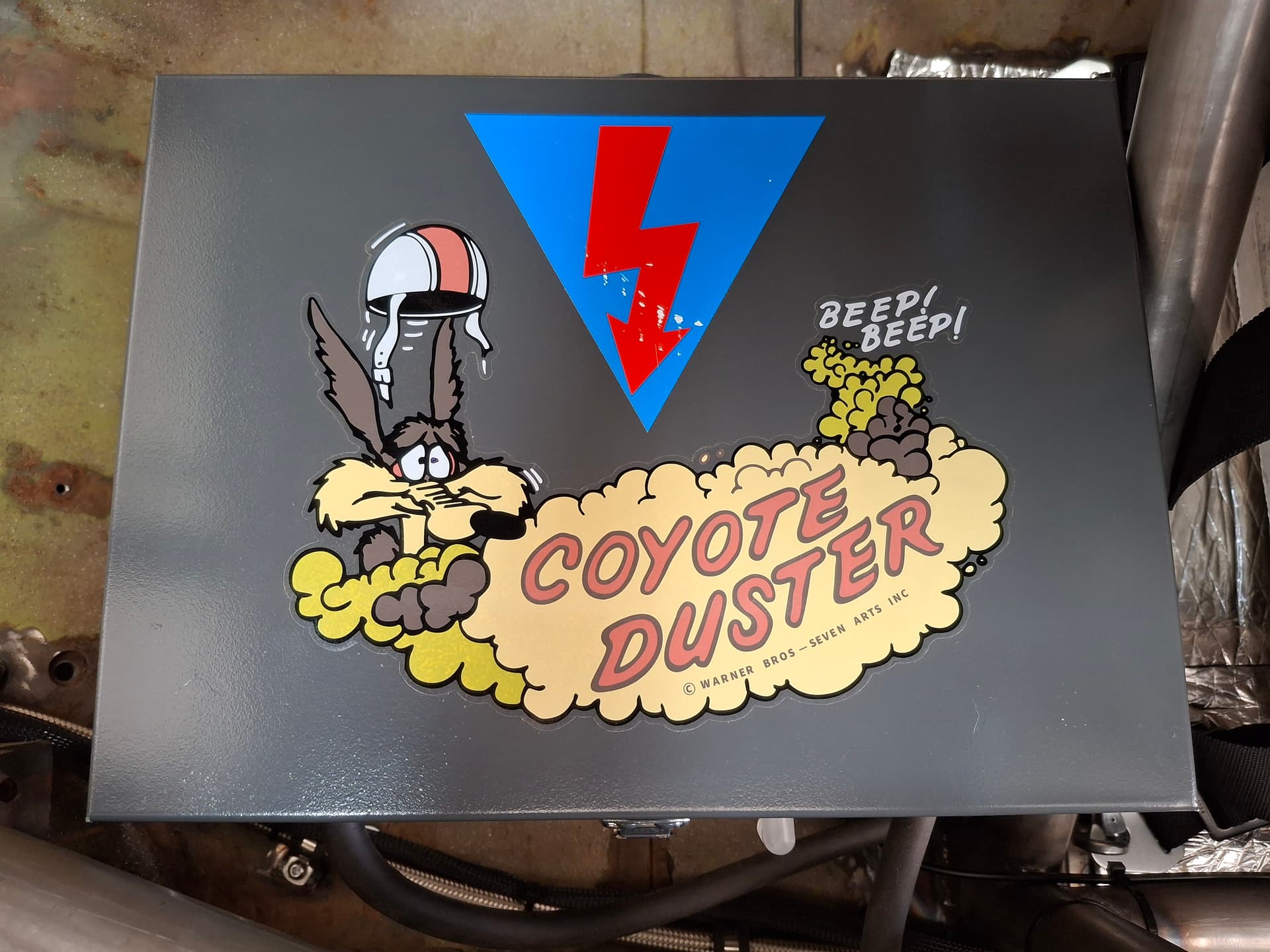
The Optima Redtop battery came in, and I did the final installation. The rubber hose zip-tied to the positive cable is extra rub protection since the cable is very close to touching the box wall. A buddy a long time ago gave me an air cleaner decal from a 1969 440 6-pack engine, which they called the Coyote Duster, and I finally found a place to use this big thing on the battery cover. ![]() Beep Beep baby!
Beep Beep baby!
Transponder Mount
Jon Whiteley @jonUU was kind enough to donate a transponder he was not using, which still holds a good charge for four days. I purchased a mount and bolted it to the front of the car.
I also installed the test version of stainless steel netting over the oil cooler and radiator. If the netting works well, I’ll build a nicer aluminum frame for it that bolts onto the core support versus using just zip ties.
Notice, also, that I stopped by DMV and registered the car, so it’s now “legal”–ahem, ahem–to make its way to my local Cars and Coffee cruise night when ready.
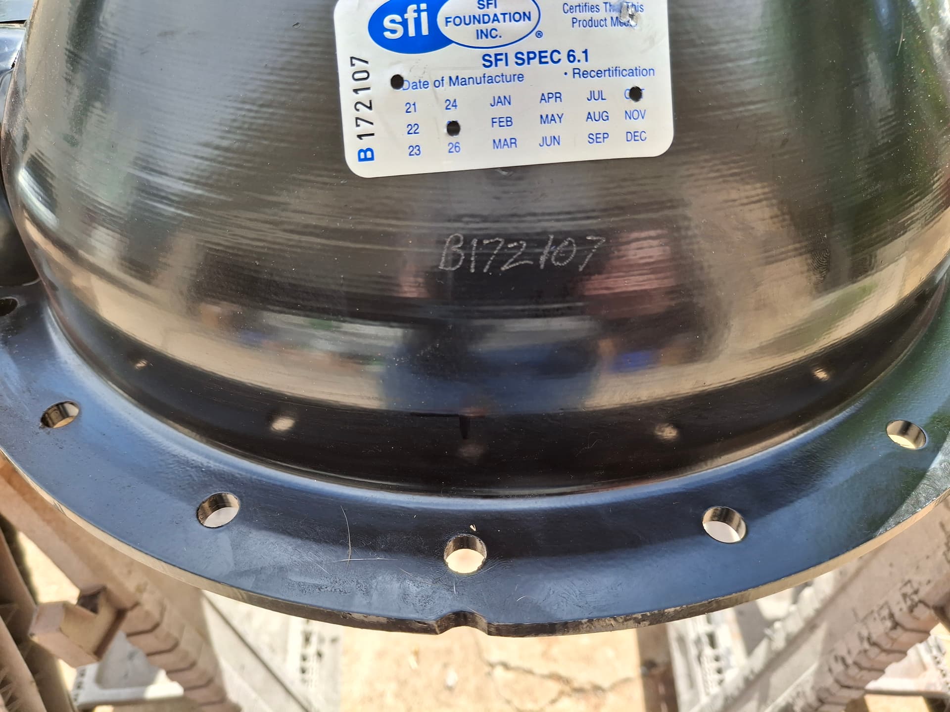
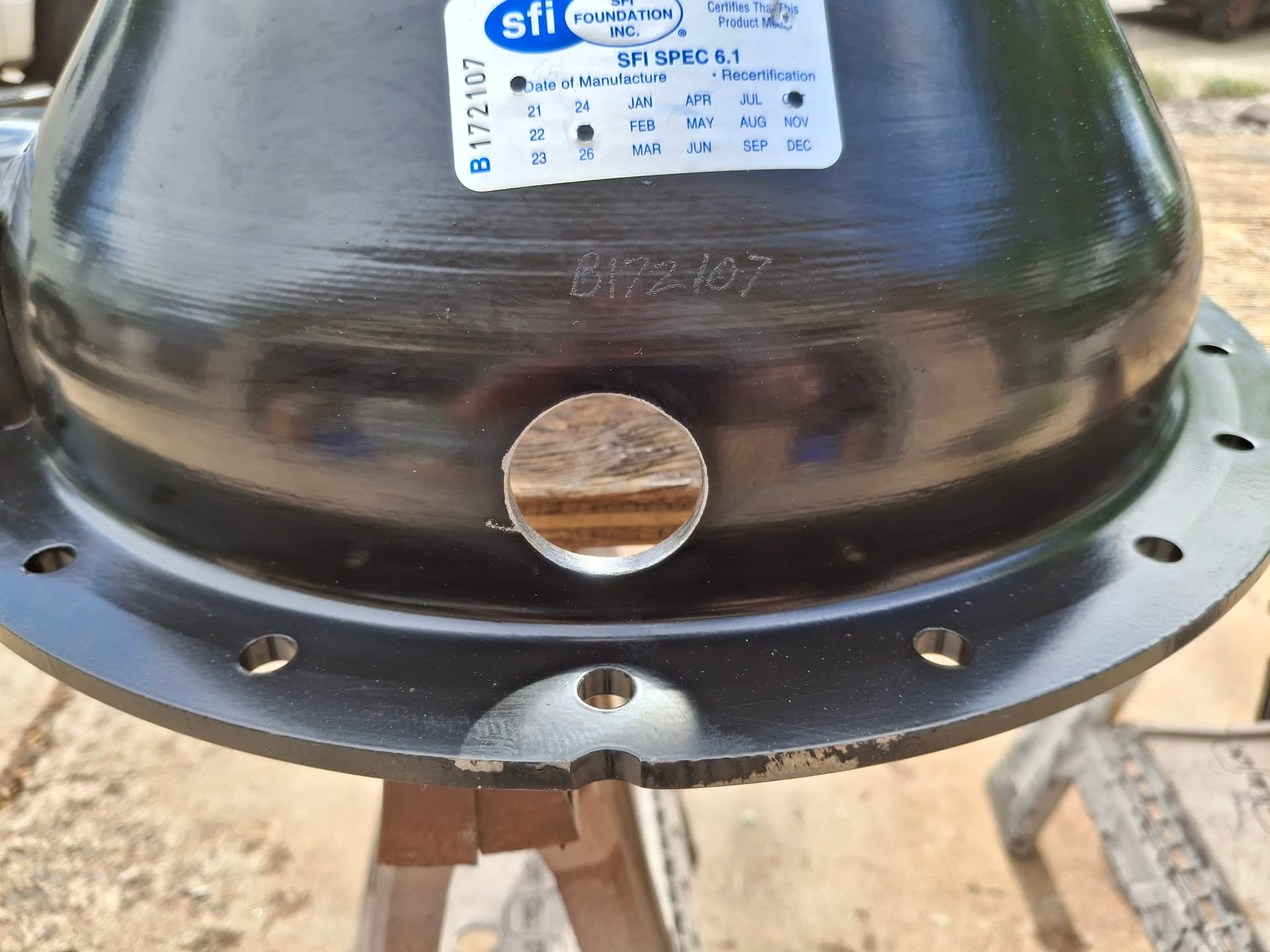
Scattershield Prep
In preparation for installing the engine and transmission, I modified the scattershield to remove the manual clutch linkage brackets since they do not clear the firewall. I also cut a hole in the bottom of the scattershield so I can easily measure the friction disc to flywheel gap with a feeler gauge to dial in the clutch throw-out bearing spacer and the clutch pedal adjustment.
Post Alert:
@jonUU
@Sportsracer
@Datsun78
@Bob_Alder
@Rich
@Nick_H
@jackson_prime101
1 Like
Justin, unless your front lower valence panel is fiberglass or something non-metallic, it’s unlikely that the track’s timing loop will “see” your transponder. Best to have a direct line-of-sight to the track.
Thanks, Jon. This is my first test spot that I’m hoping will work since it’s somewhat protected. If the system doesn’t pick it up, I intend on bolting it straight to the front spoiler face. However, the transponder won’t be protected there.
Justin the end is near!! Not to sound negative, just saying you’re almost finished. So exciting and the car is looking great.Having a license plate is icing on the cake.
One of the reasons I turned the Miata into a dedicated race car was the temptation to act 16 again when driving on the street. Just be aware the ability of grown man to grow young in a split second. ![]()
The sticker is awesome, some of the stuff mopar marketing produced was great. From the coyote/road runner cartoons to the car paint colors with their associated names. Plum crazy cones to mind.
I’m looking forward to seeing it at Pueblo, if you make it. I’m signed up but having some issues with my tow vehicle. I know race cars are expensive but diesel tow vehicles can rival them.
Tom
1 Like
So awesome to see how this car has come along. Your almost there and all your hard work is almost through! Congrats my man. Hope to see this beauty out in the near future.
1 Like
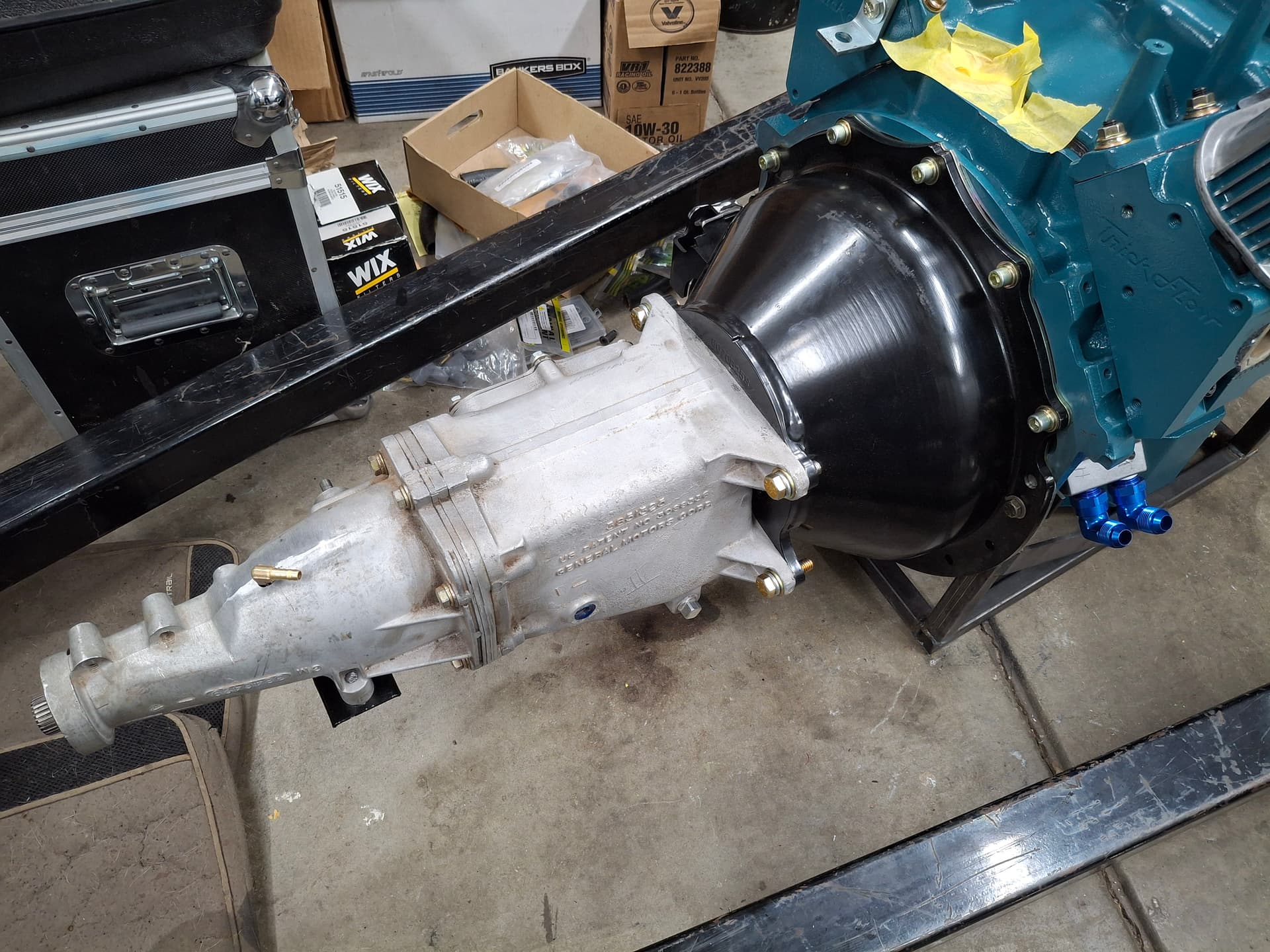
Transmission Installation Woes
As goes all things in building a Mopar race car, it’s hard to catch a break. My plan was to get the scattershield block plate, flywheel, clutch assembly, and scattershield installed last night and the transmission bolted up and the engine stabbed tonight, but that isn’t happening for a couple more nights.
I got the block plate, flywheel, clutch, and scattershield installed last night and measured for the throw-out bearing gap. Immediately, I became concerned because the throw-out bearing required 0.560" of spacing to move it toward the transmission within the 0.150" - 0.200" spec, which took the entire spacer pack included with the bearing. I had a bad feeling about the next step.
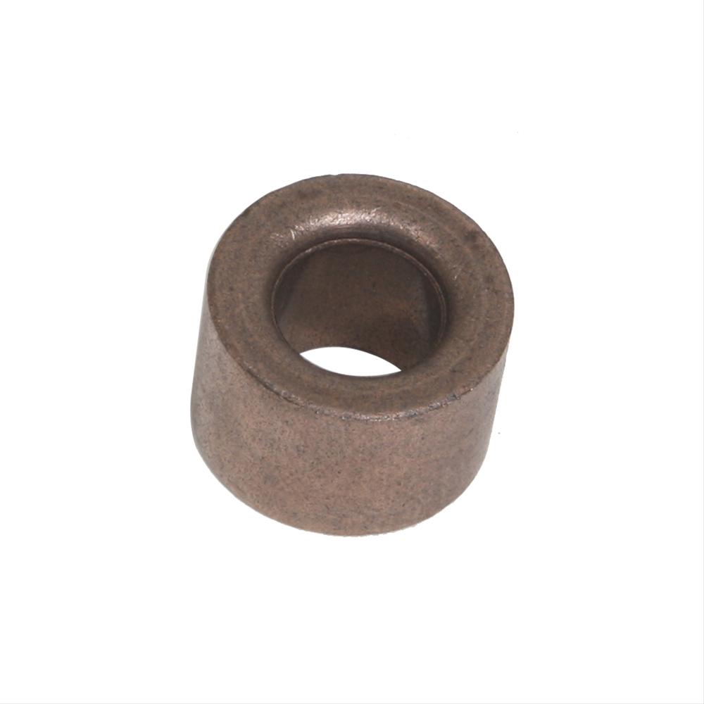
I moved on to checking the depth from the transmission flange on the bellhousing to the bronze pilot bushing I pressed into the crankshaft to compare that depth to the input shaft length to ensure the pilot snout on the shaft had enough engagement into the pilot bushing. When measuring from the bellhousing flange to the face of the pilot bushing (not even into it), the mike read 6.625". I went over to the transmission and measured from the mounting surface to the tip of the input shaft and read . . . 6.625". Ah, that isn’t gonna work since the input shaft would reach but not insert into the pilot bushing. Immediately, the QuickTime sales tech’s words from 2025 when I ordered the scattershield came to mind: “It’s a direct bolt-on swap to install a GM transmission behind a small-block Mopar. No additional parts needed. Just give me your credit card number.” By direct bolt-on, I guess he meant if you don’t want a pilot supporting the input shaft. There might be some Mopar owners running around on the street wondering why their 4th-gear shift is garbage and the transmission keeps eating bearings.
I called QuickTime and explained that their bellhousing is 1/2" too long and that the input shaft doesn’t reach the pilot bushing. They had no explanation, no solution, but confirmed that my bellhousing is built to the “correct” length per their blueprint. Thanks bud.
I called my friend Brian Garcia to see if he had any thoughts since he runs a GM Super T10 dog box, and he mentioned that there is a conversion pilot needle bearing out there that instead of pressing into the bushing bore in the crank presses into the larger well for the torque converter snout, thus moving the bearing out. Sure enough, I found it. It’s a chunk of bronze that hammers into the crank well with a needle bearing in the middle for the input pilot. It’s for a late-model Jeep conversion to a late model GM-type transmission that coincidentally shares the correct O.D. for the LA Mopar crank.
Compared to the Original Chevy Bushing:
The issue is that I don’t like it at all because of the needle bearing. My late 1960’s Muncie has a good, used input shaft whose metallurgy and machining tolerance was designed for an oilite bronze bushing and spent its life running in said bushing. It was never machined to the tolerances of being a needle bearing race, and who knows how its metallurgy would like it. More importantly, because it is used, it has some taper wear on the section that rode in the bushing compared to the section that didn’t, and it might not even be a true circle anymore due to the wear. It also has a couple forging pits in the surface. None of these irregularities matter for a bronze bushing with 0.003" clearance, but I suspect a needle bearing won’t like them and will eventually eat the input shaft and/or seize the bearing in time after so many 6,500 RPM shifts into and out of 4th. If it wear a new input shaft designed to ride in a needle bearing, I’d buy the bearing and be done with it, but that’s not my case.
After brainstorming everything my brain cooked up, I settled on buying a solid round of oilite bronze (holy heck at $20 per inch) and buying my pal @Bob_Alder lunch to go over and use his lathe to build a custom bushing. Then it dawned on me that our resident Formula Vee specialist Jess Valentine is quite the machinist, loves this kind of stuff, and might have some bronze lying around. A sketch and text message conversation with Jess later and he has the bronze and is happy to knock it out tomorrow. Sorry, Bob, lunch will have to wait ![]() This club is full of standup people.
This club is full of standup people.
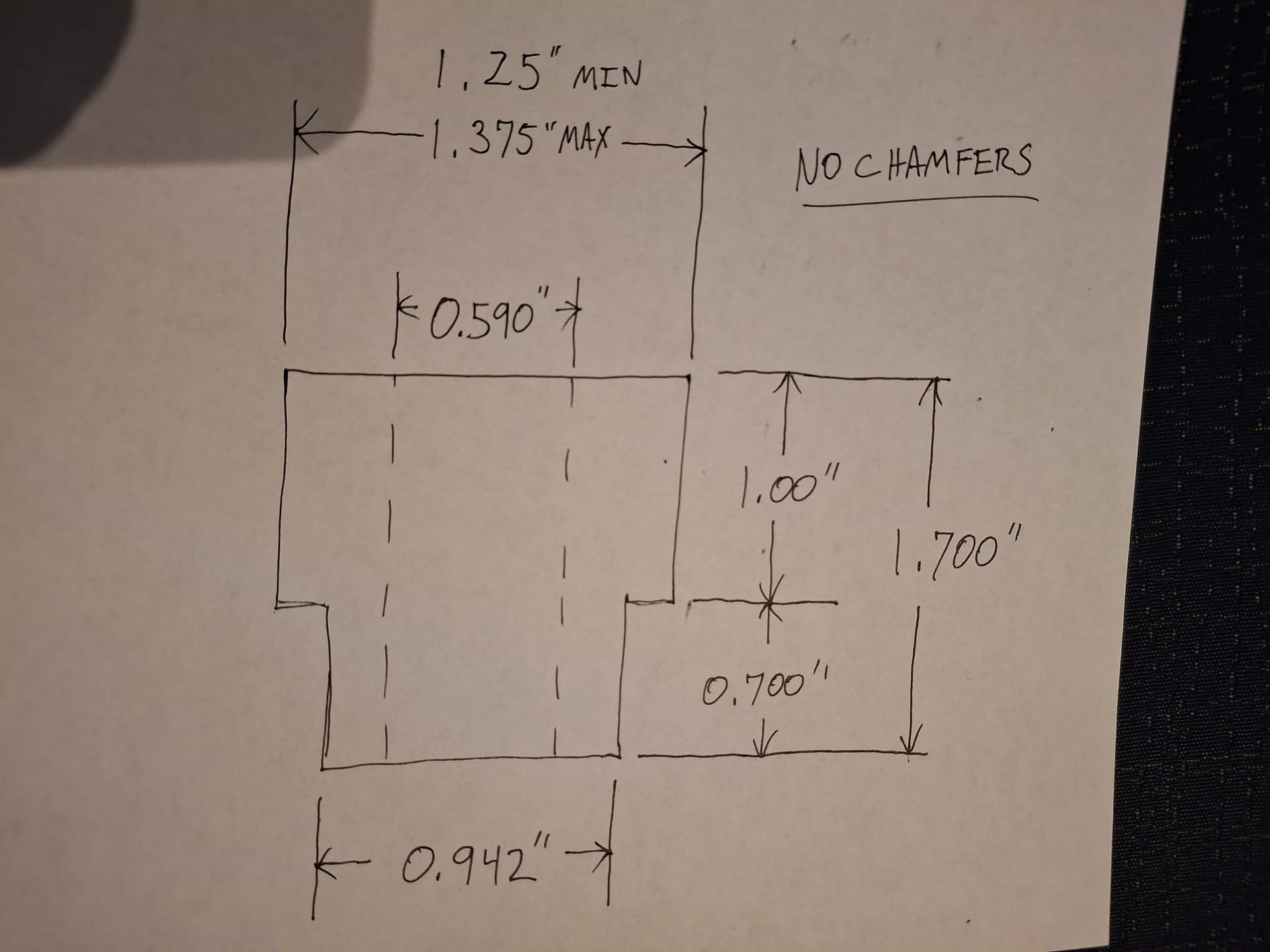
So my plan–that Jess agrees with–is to have a portion of the bushing that presses into the original crankshaft bore to secure things. The bushing then widens outside of the crank with the ledge resting tight against the crank for additional side-load support and a thicker wall for the 1" of extra bushing protruding from the crank toward the transmission that the pilot snout will ride in. With this configuration, I will get the full 1" of engagement on the input shaft pilot snout, so it should shift nicely. I also don’t expect to ever wear out the bushing with that much engagement.
So with this slight setback, my hopes of doing an initial shakedown at the IMI track next week are dashed. It’s looking like the Friday June 26 test and tune at Pueblo will be the literal maiden voyage so long as I can get the engine and transmission installed this weekend and start buttoning up and testing all the systems next week.
Post Alert:
@jonUU
@Sportsracer
@Datsun78
@Bob_Alder
@Rich
@Nick_H
@jackson_prime101
“Sorry, Bob, lunch will have to wait ![]() ”
”
No worries. My lathe sucks. Valentine’s doesn’t. Plus he’s a real machinst and I’m not.
However, if the nose of the input shaft is supposed to ride in an oilite bushing, don’t use just just any old bronze. Ain’t the same. I did that once with a bushing for an input shaft bobbin. Don’t go there. ![]()
Maybe you already were going to configure for a needle bearing pilot. Do so. ![]()
Bob
@Bob_Alder, I’m sure your lathe would get the job done just fine. I learned as a child on my dad’s 1950’s Craftsman benchtop lathe and more in high school on a 1950’s South Bend monstrosity. Coincidentally, I have the same Craftsman benchtop lathe that Pete has in his arsenal (I think a 12"), but I just don’t have the bench room in my garage to justify setting it up. It’s buried in the shed now. I’ve carried the thing around and at one point when I lived in apartments had it in the clothing closet. ![]() Even if you and I couldn’t machine the bushing correctly, we’d have fun trying
Even if you and I couldn’t machine the bushing correctly, we’d have fun trying ![]()
I appreciate the warning about the alloy. Yes, Jess is using the proper bronze, so hopefully there won’t be any unwanted fusing.
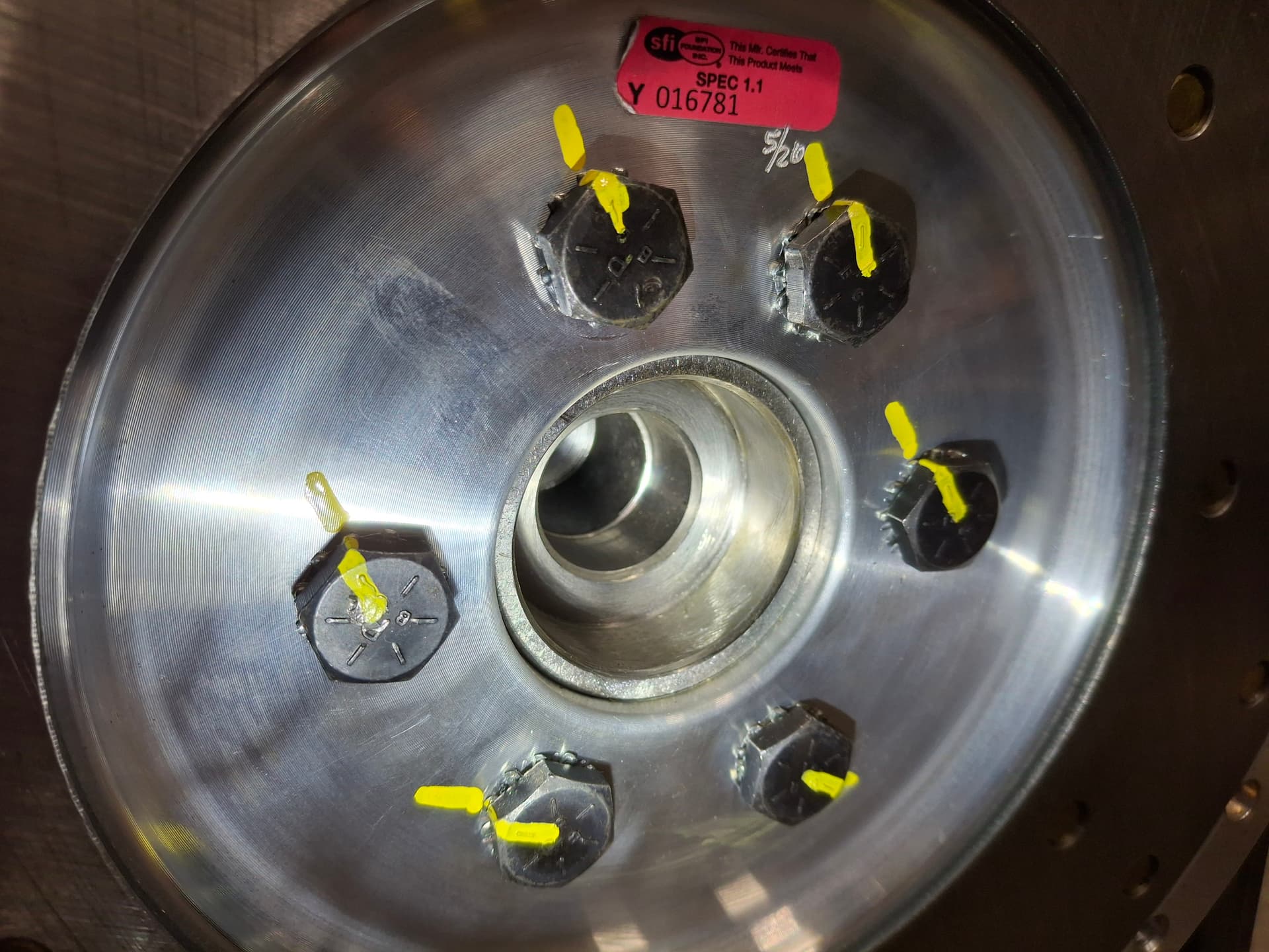
Transmission Installation
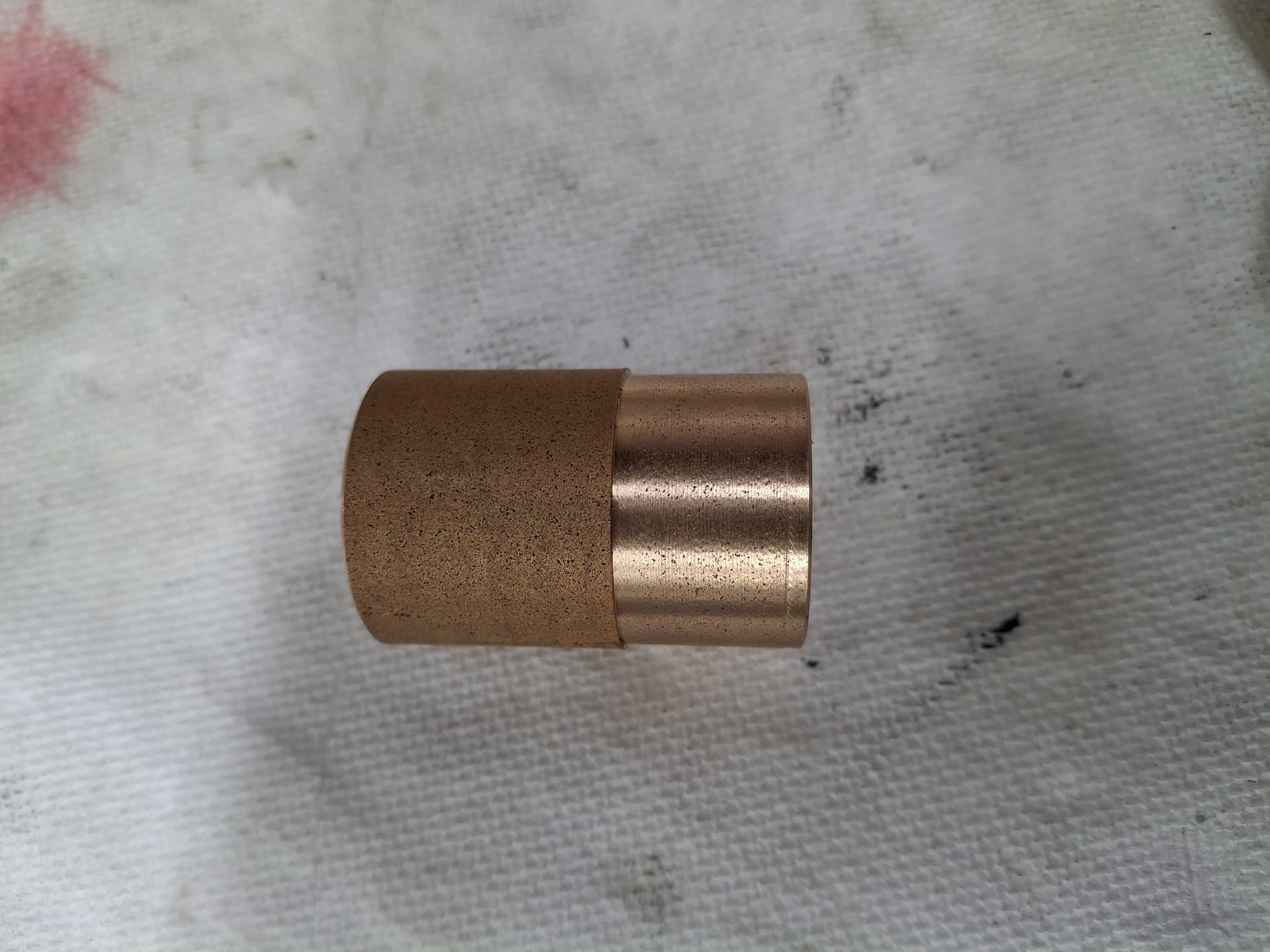
Jess Valentine came through for me! He had enough bronze for the job, and he even made me a spare. The custom elongated bushing drove in nicely.
The clutch and scattershield went on without issue. The transmission slid in with very little struggle from aligning the throughout bearing on its pin and aligning the input shaft splines on the clutch. The transmission slid up to the scattershield by hand, so alignment with the pilot bushing is on. Have you ever seen a Mopar backed by an M21 Muncie? The purists are screaming in the void ![]()
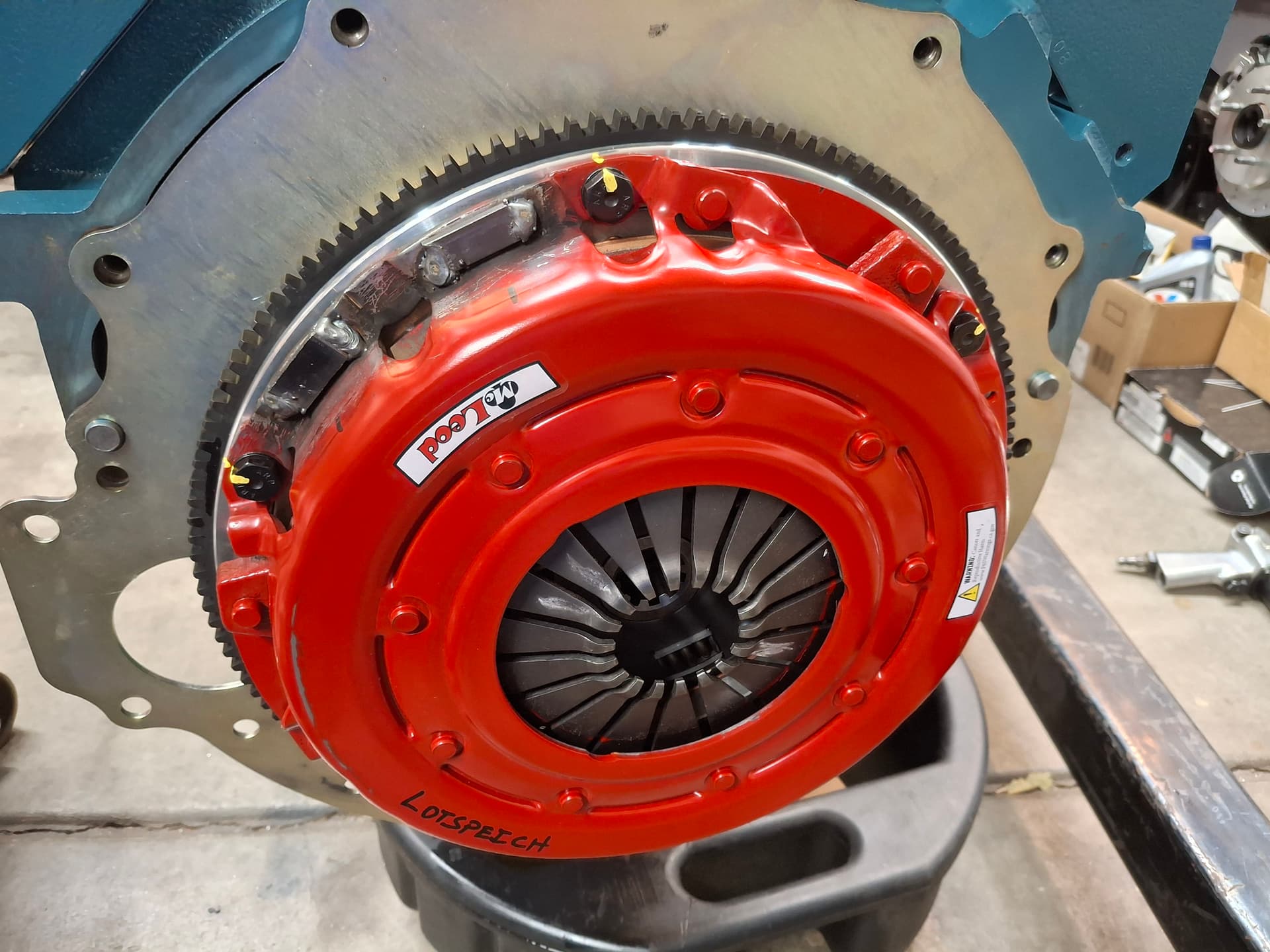
I was able to get a stack of feeler gauges through the clutch linkage hole in the scattershield, and the throw-out bearing gap is the same as my initial calculation and within spec.
Tonight, the engine goes into the car!
Post Alert:
@jonUU
@Sportsracer
@Datsun78
@Bob_Alder
@Rich
@Nick_H
@jackson_prime101
Why did you choose the Muncie and not the Mopar A-833 Justin?
Good question, Jon @jonUU. In no particular order,
- Durability
- Affordability
- Close gear ratio
- Weight
While the A833 has it’s place (like in drag racing with the 426 Hemi variant), it’s a weak link on all four of these fronts. Good close gear ratios for a road racer are rare and expensive. Core non-overdrive transmissions are expensive, used parts for rebuilding (gears, shafts, etc.) are expensive, and overhaul parts (bearings, synchros, etc.) are more costly than a Muncie or Super T10. Theoretically, I can build a Muncie using all new parts or buy a brand new Richmond Super T10, whereas practically nothing is made new for the A833.
The main reason these variables are issues is that the A833 doesn’t have a great track record for road racing and often break, which means repairs are expensive. My understanding is that the rare aluminum-case variant of the A833 was a significant reason the 1970 T/A Barracudas and Challengers had so many DNFs.
The last item that is less of a concern is that aside from the rare T/A cases, the A833 is a monstrously heavy cast-iron mother. If it were a bulletproof transmission with parts availability, I wouldn’t care about the weight, but the weight savings with the Muncie is a perk.
I figured I’d bite the bullet now on an expensive conversion scattershield and rebuild a close-ratio M21. A future upgrade might be to build a dog box.
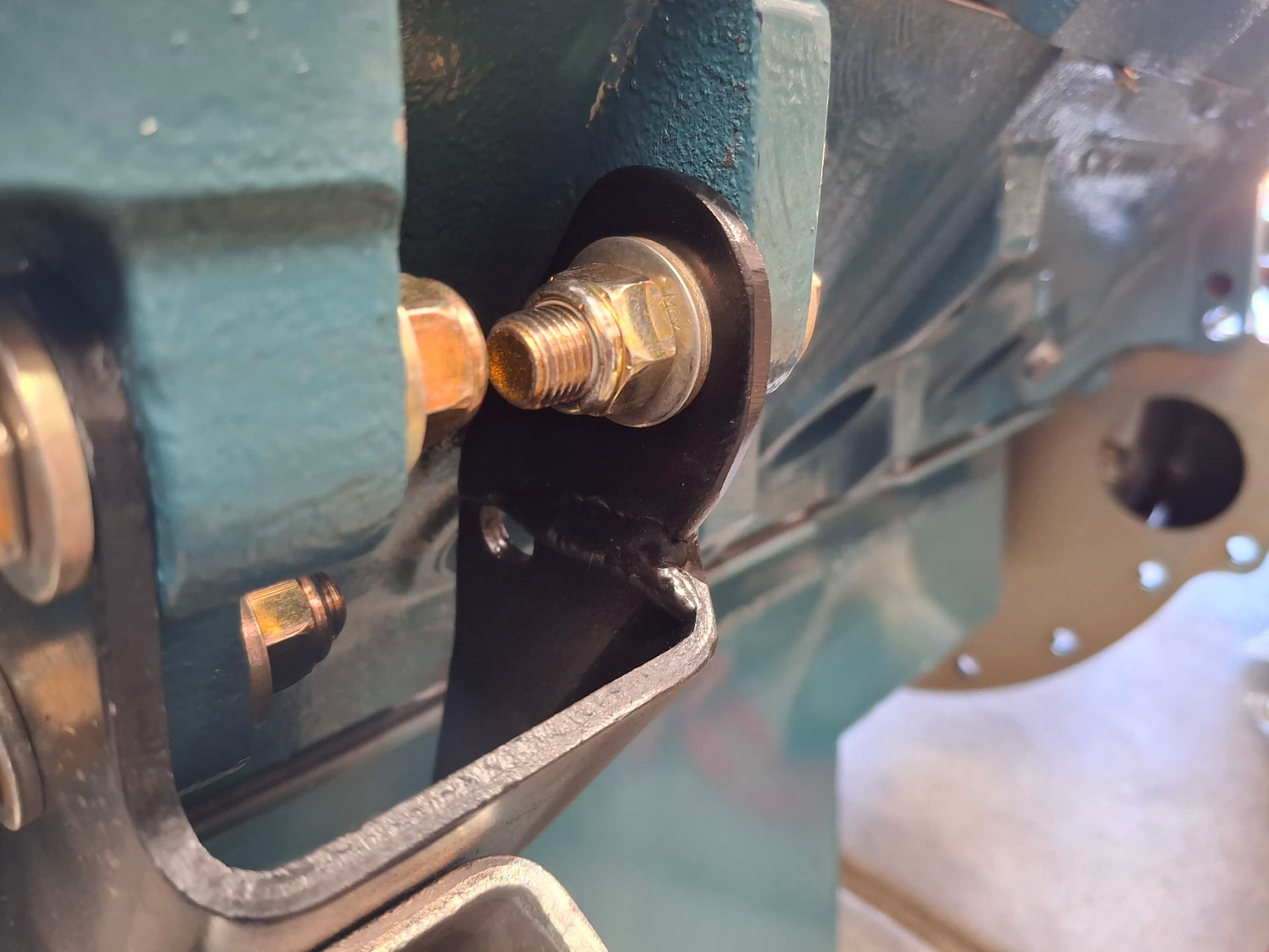
Motor Mount Head Scratcher
I both love and loathe the internet. In all my research, people on Mopar forums claimed up and down that a late-model 360 engine block, which is what I used for the engine is a “direct swap” into a 318 car as far as the block goes. Shame on me that I took them at their word. As you know, I used the original 318 from the car for all my mock-up, and I sandblasted and painted the 318 motor mount brackets. You might imagine my bewilderment when I bolted the motor mount brackets onto the new engine and found that the right side bolted up perfectly but the left’s rear hole had nothing to bolt to on the block. Yeah, so it turns out all those internet experts–even a website dedicated to the swap–neglected to point out that the late-model 360 block moved the mounting ear up and used a different left motor mount bracket. Had I have known that, I would have modified my 318 bracket prior to painting it, or I would have sourced a 360 bracket. I elongated the bracket with some plate, and everything is good now. The whole process just took much longer than I expected compared to bolting on brackets.
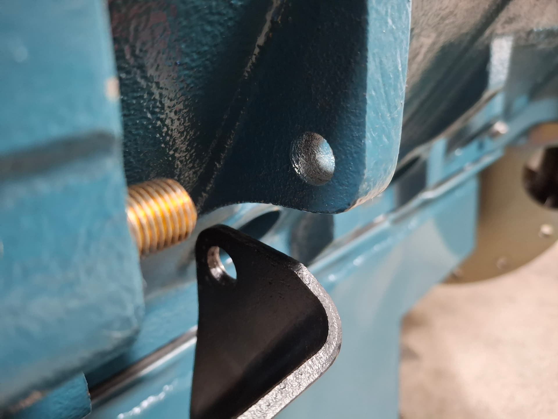
(Note in the following photo that I have the bracket bolted on the front of the ears when for the final installation it went on the backside of the ears).
Transmissions and a Pint of Brake Fluid on the Floor
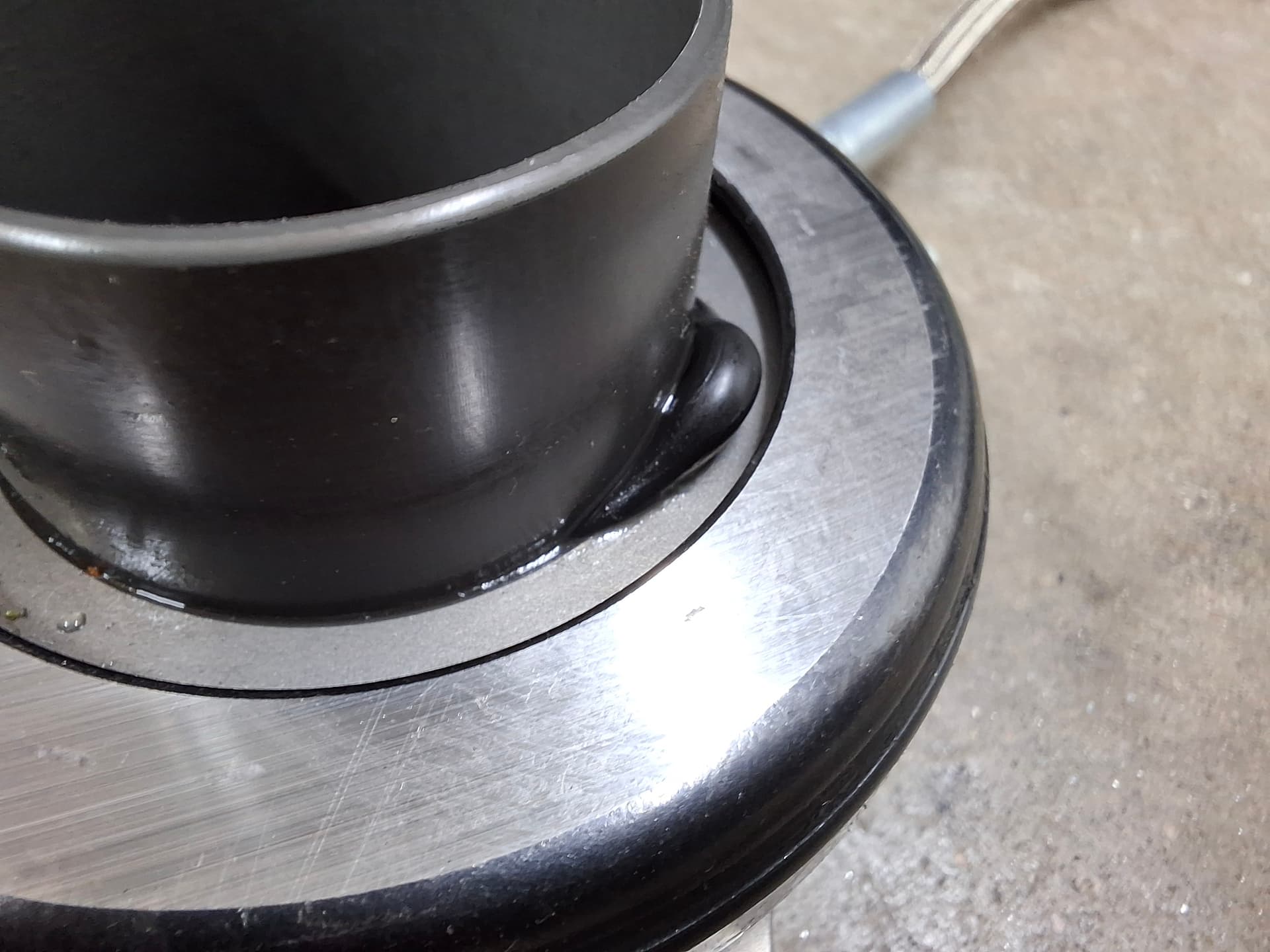
I still can’t catch a break when it comes to parts quality. I purchased a high-dollar RAM USA-made hydraulic throw-out bearing to simply things. When I first inspected it, I noticed it didn’t seem to have an external limiter to protect the bearing from overextending and falling off the front of the inner shaft. However, the instructions clearly say that so long as the air gap between the bearing and pressure-plate springs when the bearing is fully compressed is between 0.150" - 0.200" and so long as the master cylinder is 3/4" bore, no pedal limiter is required. So I, stupidly apparently, trusted the instructions and installed the unit to those specs.
Once I got the engine and transmission installed, I filled the clutch master cylinder with brake fluid, gravity bled the bearing, and got in the car. From inside with the transmission tunnel cover off, I have a direct view to part of the bearing through the clutch fork hole in the scattershield. I slowly began pumping the pedal until it started building pressure. Eventually, I had a nice, firm pedal and could feel and see the springs compressing as the bearing moved forward. All seemed really smooth, until it was too smooth. At one point, when I had depressed the pedal about 1", the pedal went to the floor, I heard a hissing noise, and I watch a pint of brake fluid pour out of the bottom of the scattershield onto the floor. Wonderful. With that and a couple curse words, I called it a night.
This morning, I pulled the transmission, which, luckily, only required disconnecting the throw-out bearing hose, disconnecting the breather hose, and removing the transmission crossmember since I hadn’t installed the shifter linkage and drive shaft yet. Also, luckily, I didn’t see signs that the clutch disc got soaked, but I sprayed the heck out of it with a brake clean just in case. @jonUU, that decision to go with the Muncie was a blessing since it’s an easy bench press down onto my chest and roll on to the floor. If it had been a cast-iron A833, I would have crushed myself ![]()
As for the throw-out bearing, one of the inner o-ring seals blew out. I cannot say for sure if this was from overextending, but it certainly seems like the most plausible answer versus the master cylinder building enough pressure to squeeze such a large o-ring out such a small clearance. I’m disappointed in RAM to say the least. If they had explained that this bearing is even capable of overextending when installed per the specs and that a pedal limiter should be installed, I would have done so. I have a new seal kit on the way for delivery Monday. After I get the transmission back in and the master cylinder/bearing bled to where the bearing just starts to function, I’m going to have Rosalia slowly depress the pedal while I lie under the car looking up through the inspection hole. As soon as the clutch disc and flywheel have an airgap of 0.050" - 0.080" per McLeod’s instructions, I’ll have her stop and hold the pedal. I’ll then measure the distance from the pedal to the floor and build an adjustable pedal stop so overextending is impossible. The benefit there is that I can guarantee the quickest shift by depressing the pedal until it hits the stop. It’s an absolutely stupid design that they don’t have a snap ring on the inner bearing shaft to stop the bearing from overextending.
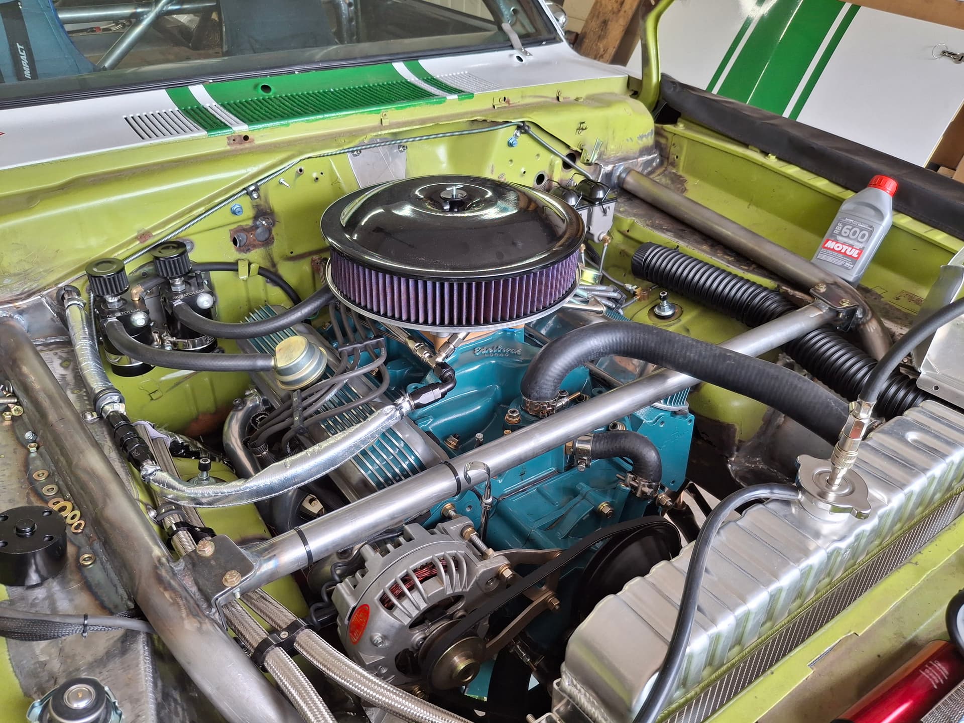
Engine Installation and System Tests
To end on a high note despite the throw-out bearing b.s., the engine is installed, the oil cooler and filter system installed and tested, and the fuel system installed and tested.
Oil System: I drained the dyno oil and filled the pan with 7 quarts of fresh oil where I know the fill line rests just under the sump cover. With everything installed, the accumulator valve closed, and the remote oil filter filled with a quart of new oil, I spun up the pump with a drill. The system built 50 PSI quickly. I topped off the pan to find that the system minus the accumulator takes 3.25 quarts including the filter. I opened the accumulator and primed again, and I saw the same 50 PSI on the accumulator gauge that I showed on my mechanical priming gauge in the block. I didn’t have anyone to close the accumulator to check it’s capacity, which I’ll do later, but it is advertised as a 3-quart. All in, if the accumulator holds 3 quarts, the oil system holds 13.25. Cha ching for oil changes baby! The only leaks were from both of the NPT-to-AN adapter fittings in the remote filter housing. I removed them, reapplied sealant, and snugged them again and was able to stop the bleed.
Ignition System: I installed the distributor and plug wires. With the two electrical master disconnect switches on, the ignition box shows a ready status. That’s as far as I’ll test until I fire the engine.
Fuel System: I first wanted to flush the fuel cell and lines even though I was careful to blow out everything with air during installation. I placed the fuel feed hose in the engine compartment into an empty gas can. Testing out my new battery powered fuel transfer pump, I pumped 5 gallons of fresh 100-octane AV gas into the cell. The safety switch system I installed allows the pump to run without oil pressure only when the starter is powered, so I simply left the starter trigger wire disconnected from the starter. With the two electrical master disconnect switches on, the fuel level gauge showed fuel in the tank. I held the starter bottom, and the pump spun up. After about 10 seconds, I checked the gas can and found no fuel. I cracked the connection in the trunk just after the fine filter and found no fuel. I held the starter bottom for another 30 seconds or so and checked the above again and found no fuel. The pump obviously wasn’t priming itself.
I disconnected the fuel cell vent hose and blew some compressed air in to pressurize the tank, which did the track when I got fuel at the filter connection. I held the starter button and heard/saw fuel dumping into the can. I filled the can until the fuel started sputtering. With 4 gallons in the can, the fuel cell requires 1 gallon of fuel to reach the pickup when level, so I noted that the tank will be minus 1 gallon capacity. I filled the tank with another 5 gallons, connected the fuel line to the carburetor distribution manifold, and held the starter. I had to deal with a pesky leak at one of the manifold fittings that strangely enough wasn’t an issue on the dyno but now was, but I was able to stop it.
With no other leaks present, I held the starter again and found 3 PSI on the fuel-pressure gauge. I adjusted the pressure regulator in the trunk until I had a steady 6 PSI (AED’s spec, who built the carburetor) and kept the pump spinning for a few minutes to test the system for leaks. I found none.
Cooling System: I installed the radiator on rubber isolation pads, installed the radiator hoses, and began filling the system. I’m using VP Racing “Stay Frosty” coolant, of which I thought I had three gallons but only found two. The coolant didn’t reach the top tank, so I ordered another two gallons that arrive Monday. While I don’t know how for up the coolant is in the block, I pressurized the system to the caps 16 PSI rating and found no leaks, but I’ll do so again after I get the system filled. I didn’t have grade 5 or 8 bolts long enough for my fan spacer, so I’ll pick some up Monday evening.
While I wasn’t able to meet my goal of firing the engine and driving the car a few feet into the driveway, I had a very productive weekend. Monday will bring new parts, hopefully, and Monday night will see the transmission back in and the coolant system checked for leaks. If all goes well, I hope to button everything up this week for neighborhood test driving this coming weekend. Sorry for any typos in this post since I’m not going to proof it and instead go treat myself to a Mexican dinner while Rosalia is out of town. Her loss ![]()
Cheers!
Post Alert:
@jonUU
@Sportsracer
@Datsun78
@Bob_Alder
@Rich
@Nick_H
@jackson_prime101
Justin
Looking good and getting exciting! As with all things race car, the motto adapt and overcome presides. I know you’ll get there and looking forward to Pueblo. I’m not going to participate in the Friday test n tune but I will be there Friday afternoon. Tow vehicle problems not withstanding.
Today I get to install new charge tubes, both hot and cold side. After my failed trip to northern New Mexico a few weeks ago, I had the truck deleted to resolve a code issue that could not be cleared. As a result of the delete I now have higher boost pressure (a good thing as the mileage is incredible, 1/4 tank from walsenburg to Denver) causing the hot side tube to blow off the turbo on my driver home from the repair shop. Most likely my fault as I was enjoying the extra performance and hot footing it.
Racers can stop racing!
Best
Tom
Tom, Thanks for the encouragement. I don’t have much of a choice to adapt and overcome, so I push ahead. You’re right that most of us have been and are in the same boat there.
Sorry about your continued truck issues. Hopefully with the new tubes, the issue will be resolved. I look forward to seeing you at Pueblo.
The Punches Keep Coming: Ignition WTF
Well, remember that part about the build not being very giving in breaks? Yeah, I’ve got another WTF moment for you.
The new throw-out bearing seals came in, I overhauled the unit, got it installed, and dialed in all the air gaps along with a physical pedal limiter. All appears to be good on that front.
After I installed the shifter linkage and did a final review of my work including checking fuel in the carb, I decided to try and fire the engine early yesterday evening. All the electrical systems powered up just fine, and the PerTronix Digital HP ignition box showed the green “run” status light. Excitement and a bit of nervousness filled the air, I held down the starter button, and the engine started turning over very nicely. However, it wouldn’t fire or even try, so, after another pump of the gas pedal without change, I suspected ignition. I pulled a plug wire and cranked the engine again to find no spark.
With both my digital multimeter and analog volt meter in hand, I started testing. I had 12.5V at the ignition box plug. Cool. I had no power at the positive side of the coil both with the master switch on and with the engine cranking. Not cool.
Okay, so what happens if I disconnect the positive wire to the coil and jump 12V from a 20A fused circuit so I can test the negative side of the coil? I did so, turned on the master switch, and the fuse immediately blew. I replaced the fuse, removed the negative coil wire from the ignition box, and turned on the switch again, and all was fine with current at both sides of the coil. So there is something wrong in the PerTronix box that is both stopping current from getting to the positive coil wire and shorting to ground when the coil is fed current.
The irony is that I spent a lot of time researching which box to use including calling both PerTronix and MSD, and I chose PerTronix because the box is still made in the USA, whereas the MSD 6AL is now made in China. Hopefully I can get a replacement unit and not have an issue with it before Pueblo.
This issue might be the last straw for my dedication to USA parts. Almost all the USA-made parts I’ve gotten for the build have had terrible quality issues including the McLeod clutch pressure plate (bent), RAM throw-out bearing (blown), two different models of Harland Sharp rocker arms (damaged and sloppy tolerances), Howards roller lifters (a pair riveted backwards), Trick Flow heads (push rod channels incorrectly machined and sloppy CNC porting), Doug’s Headers (impossible to fit the car they were supposedly designed for without moving tubes), PerTronix ignition box (internal short), SCAT crankshaft (inconsistent metallurgy), Moroso solid motor mounts (1/4" taller than advertised), and I’m probably forgetting some others since there have been so many. Why bother paying the premium when both the parts and customer service quality are worse than imports?
I’ll keep plugging away at the list of remaining items to finish the car and will await a new ignition box.
Post Alert:
@jonUU
@Sportsracer
@Datsun78
@Bob_Alder
@Rich
@Nick_H
@jackson_prime101
What a damning litany of shoddy workmanship. A far cry from when the phrase “Made in the U.S.A.” was a triumphant shout to the world. So sad.